
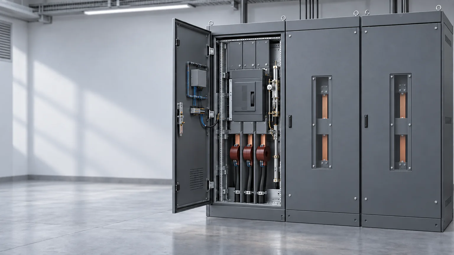

Need a clear switchgear components list? Start with the job each part performs—not with a catalog photo. Switchgear is an assembly that carries power, switches and isolates circuits, detects abnormal conditions, operates the interruption device, and contains the interfaces around it. The component list changes with voltage class, operating duty, insulation system, cabinet architecture, and project scope.
For a replacement or RFQ, ask three questions:
- What function does the component perform?
- Which power, control, measurement, or mechanical interface does it touch?
- What must match before the part can be quoted or released?
A breaker can match the voltage and current rating and still fail in the lineup because its primary contacts, mechanism, secondary plug, control voltage, or interlocks are different. The same rule applies to relays, CTs/VTs, busbars, cable entries, and enclosure compartments.
This guide explains the components and interfaces at a system level. It does not replace the responsible engineer’s selection, protection coordination, short-circuit study, or compliance review. When defining the enclosure scope versus control-panel scope, prepare the drawings, dimensions, cable entries, environmental conditions, and retained-scope requirements before requesting a price.
Quick answer: What are the main switchgear components?
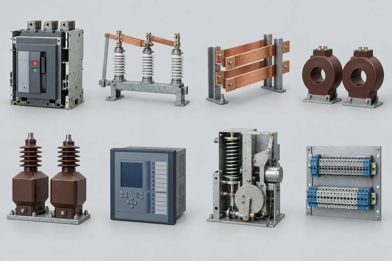
Switchgear components are the devices and interfaces that carry, switch, isolate, protect, measure, control, and contain an electrical power system. Typical groups include circuit breakers, disconnects, busbars, CTs/VTs, protection relays, operating mechanisms, auxiliary circuits, interlocks, insulation parts, and the enclosure.
Use the table to map each function to the information a buyer must confirm. Some items are separate devices; others may be integrated, optional, or outside a particular assembly.
| Component group | What it does | What a buyer must confirm |
|---|---|---|
| Circuit breaker or interrupting device | Opens the current path under defined operating and fault conditions | Switching duty, interrupting duty, mechanism, ratings, and control power |
| Disconnect or load-break switch | Isolates equipment or switches load current within its rated duty | Whether the device is for isolation, load switching, or fault interruption |
| Fuse and surge arrester | Provide overcurrent or overvoltage protection | Coordination, energy duty, replacement method, and application limits |
| Busbars and primary connections | Carry and distribute power between incomers, ties, and feeders | Arrangement, phase spacing, connection geometry, material, and access |
| CTs, VTs/PTs, or sensors | Supply measurement signals for protection, metering, or control | Purpose, ratio, accuracy, insulation, outputs, and secondary connections |
| Protection relay or trip unit | Detects defined abnormal conditions and initiates action | Protection functions, settings, inputs, outputs, and responsibility for coordination |
| Operating mechanism and coils | Open, close, or trip the switching device | Coil data, stored-energy mechanism, stroke, motor supply, and duty |
| Auxiliary contacts and control circuits | Carry commands and return equipment-status signals | Control voltage, terminal numbers, plugs, feedback, and local/remote control |
| Interlocks, shutters, and position indicators | Prevent invalid operations and show the equipment state | Mechanical positions, electrical permissives, blocking logic, and test method |
| Insulators, bushings, contact boxes, and barriers | Support conductors and maintain insulation boundaries | Connection dimensions, insulation system, clearances, and environmental limits |
| Enclosure and compartments | Separate equipment, provide access, and support maintenance and containment | Cabinet dimensions, access direction, segregation, lifting, and cable entry |
| Monitoring and communication equipment | Report state, measurements, alarms, and diagnostic information | Protocol, point list, network boundary, and service responsibility |
Treat this as a scoping map, not a bill of materials. The equipment designer still decides which parts the actual duty and architecture require.
1. Switching and power-carrying components
Circuit breakers: the device that carries out the trip
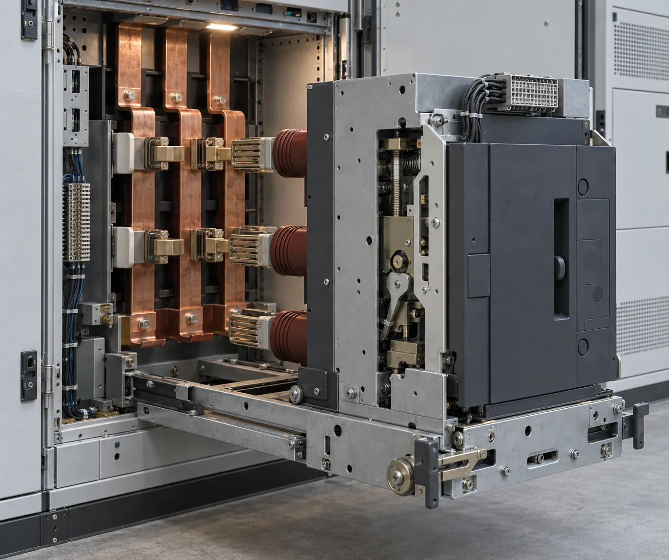
A circuit breaker physically opens the circuit. It does not, by itself, explain why the circuit should open. In a typical protection sequence, a relay or trip unit recognizes a defined condition, sends a command through the trip circuit, and the breaker mechanism separates the contacts.
That distinction is useful when comparing equipment. Ask two separate questions:
- Who makes the protection decision?
- Which device carries out the interruption?
In low-voltage switchgear, the breaker may include an electronic trip unit and several control accessories. In medium-voltage switchgear, the breaker often sits inside a larger cabinet arrangement with primary disconnects, instrument transformers or sensors, protection relays, shutters, grounding provisions, and interlocks.
The breaker rating is only one part of the selection. The mechanism, contact arrangement, operating duty, control circuit, mounting position, and connection interface can be just as important—especially in retrofit work.
For the device-level sequence—from the trip signal to contact separation—see how a circuit breaker works.
Disconnects, load-break switches, fuses, and surge arresters
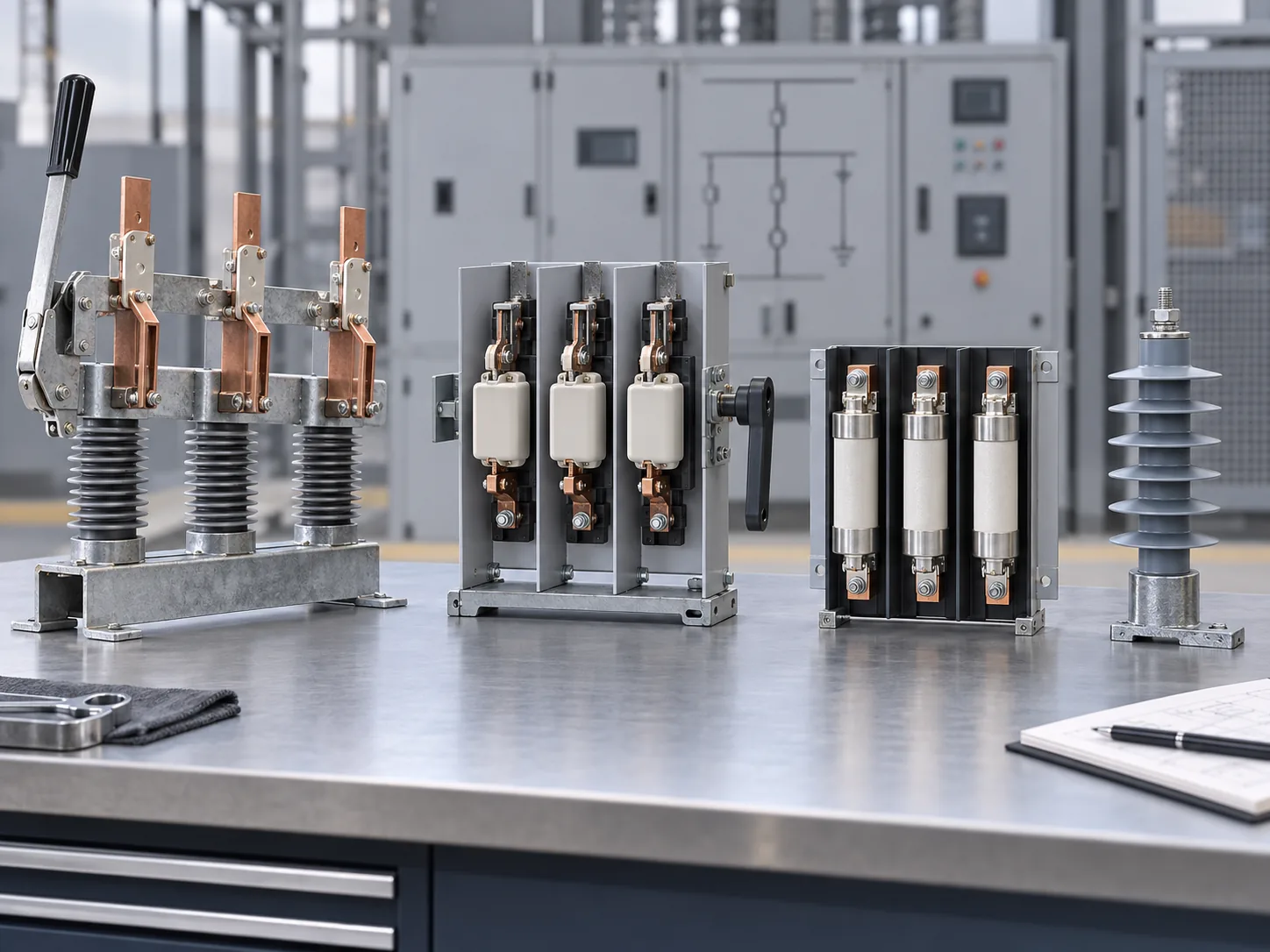
These devices have different jobs. Calling all of them “switches” creates problems later in a specification or RFQ.
- A disconnecting device is used to isolate a circuit or piece of equipment within its intended design.
- A load-break switch is designed to switch a specified load current. That does not automatically make it a circuit breaker.
- A fuse interrupts overcurrent through a fusible element and normally requires a different replacement and coordination process.
- A surge arrester limits overvoltage stress. It does not replace overcurrent protection.
Name the duty in the RFQ, not just the component. “Provide a switch” is weak. “Provide a device for feeder isolation,” “provide a load-break function,” or “provide fault interruption at the stated duty” gives the supplier an engineerable requirement.
Busbars and primary connections
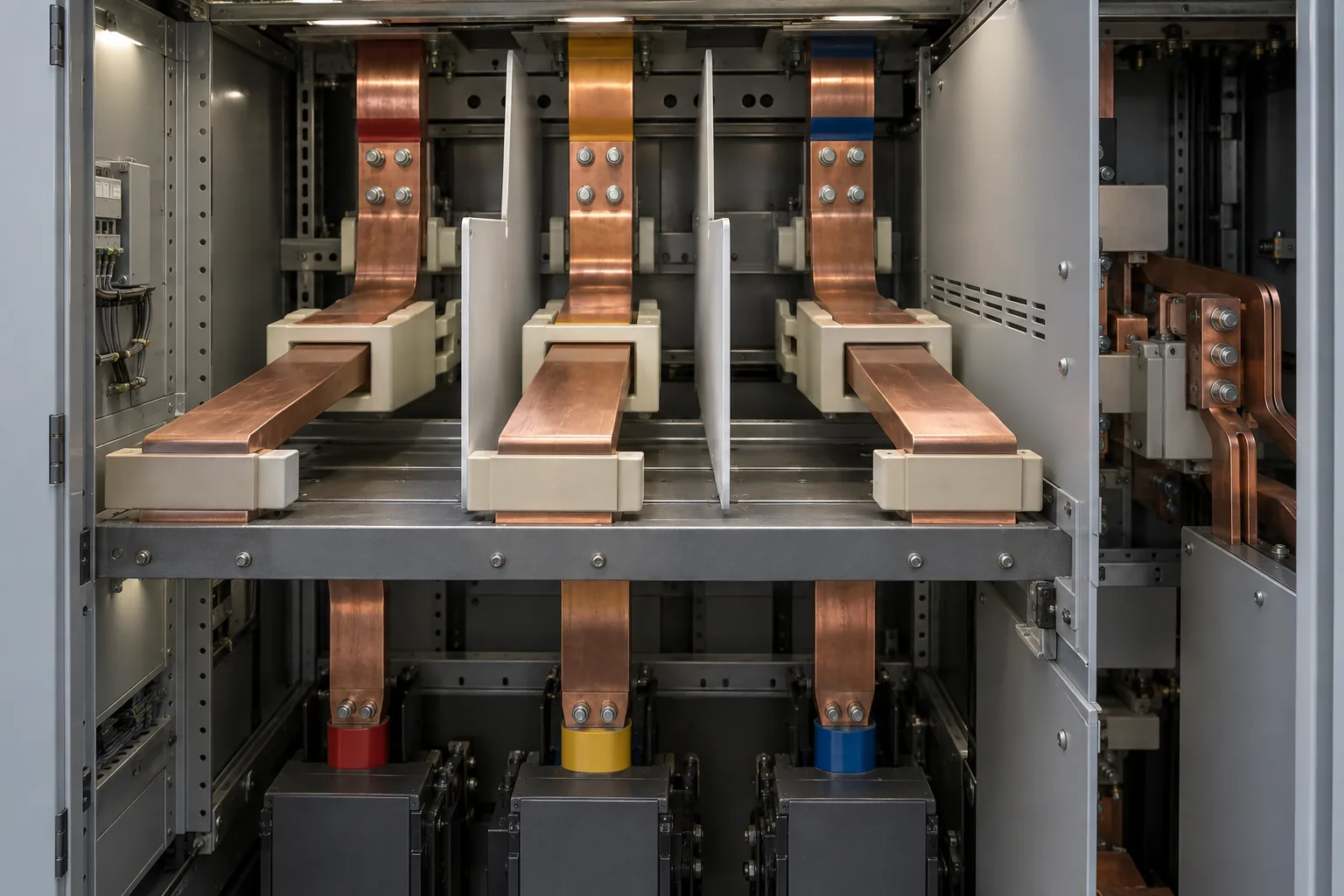
Busbars are the main internal power paths in many switchgear assemblies. They connect incomers, bus ties, and outgoing feeders. Their supports, barriers, contact assemblies, and joints maintain the required geometry and insulation boundary.
For a new lineup, the busbar arrangement is part of the design. For a retrofit, it becomes a physical constraint. The replacement may need to match:
- phase spacing;
- front-to-rear connection depth;
- primary disconnect position;
- contact finger or stab geometry;
- bolted-joint arrangement;
- cable direction and bending space;
- available working and maintenance space.
A nameplate match is not a geometry match. A replacement breaker can be electrically suitable and mechanically unusable. Terasaki’s ACB retrofit guidance and Eaton’s switchgear refurbishment case show why existing drawings, photographs, and measured dimensions matter before a quote is issued.
2. Measurement and protection components
CTs, VTs/PTs, and sensors: the measurement interface
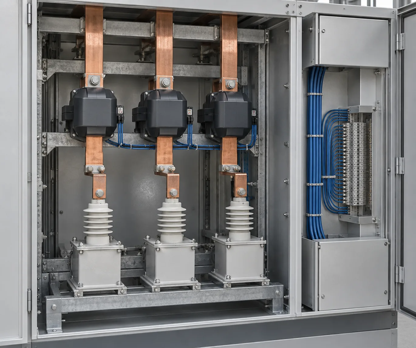
Protection and metering depend on the measurement signal they receive. Current transformers, voltage transformers or potential transformers, capacitive sensors, and newer current- and voltage-sensing systems are not interchangeable simply because they all “measure voltage or current.” Their purpose, accuracy, insulation, location, output, and connected device matter.
Before specifying a measurement component, answer these questions:
- Is the signal for protection, metering, indication, control, or more than one function?
- What primary rating, ratio, accuracy, burden, insulation, and installation position are required?
- Does the signal connect to a relay, meter, controller, process bus, or another device?
- Who owns the settings, calibration, testing, and acceptance?
The answer changes the component selection. In a Helsinki smart-grid project, medium-voltage switchgear, protection relays, sensors, and digital communication were treated as one measurement and protection chain—not as isolated accessories.
Protection relays and trip units: the decision-making layer
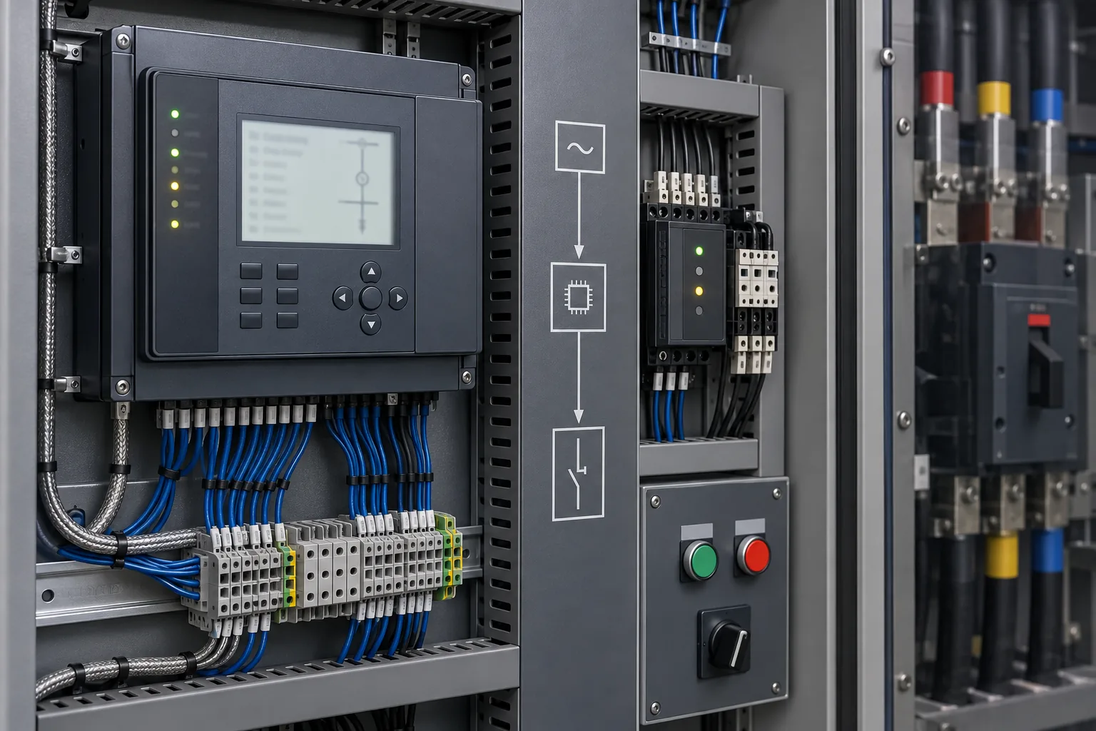
The relay or trip unit evaluates measured conditions against the protection logic and settings. Depending on the equipment, it may provide overcurrent, earth-fault, undervoltage, overvoltage, differential, breaker-failure, arc-flash, or other protection functions. The applicable functions must come from the project protection requirements, not from a generic checklist.
A relay and a breaker are not the same thing:
- The relay or trip unit evaluates the condition.
- The trip circuit transfers the command.
- The operating mechanism moves the device.
- The breaker or interrupting device opens the current path.
- The auxiliary contacts report whether the commanded state was reached.
In a digital system, relays may also exchange information with other relays, controllers, or SCADA. The LKAB case used IEC 61850-based communication and GOOSE messaging as part of the protection and control architecture. That is why a digital retrofit needs a communication and logic review, not just a relay model number.
3. Operating mechanisms, control circuits, and interlocks
Operating mechanisms and control power
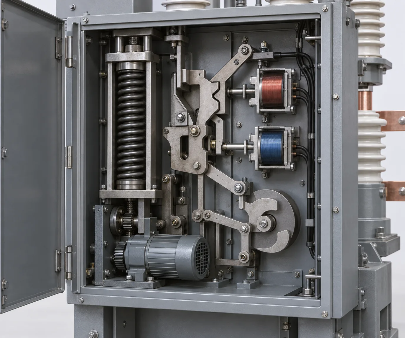
The operating mechanism turns an electrical command or manual action into movement. It may include stored-energy springs, charging motors, closing coils, trip coils, latches, links, and position indicators.
The control circuit is a separate interface from the main power circuit. Confirm it separately. A replacement can fit the power path and still fail to operate if the control voltage, coil, secondary plug, terminal allocation, or auxiliary contacts are wrong.
For the control-side parts and buyer checks, compare electrical control panel components; then confirm the switchgear-specific coil data, terminal allocation, and feedback signals.
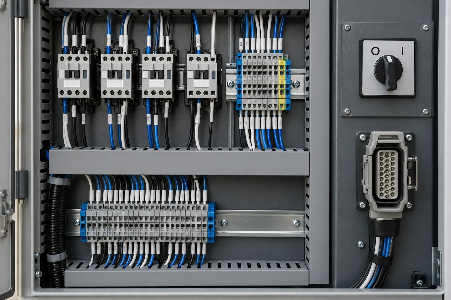
For a replacement or retrofit, request or verify:
- control voltage and tolerance;
- closing-coil and trip-coil data;
- spring-charging motor supply;
- anti-pumping logic;
- trip-circuit supervision;
- auxiliary contact allocation;
- terminal and plug arrangement;
- local/remote control requirements;
- open, closed, test, service, and disconnected position feedback.
Interlocks, shutters, and position systems
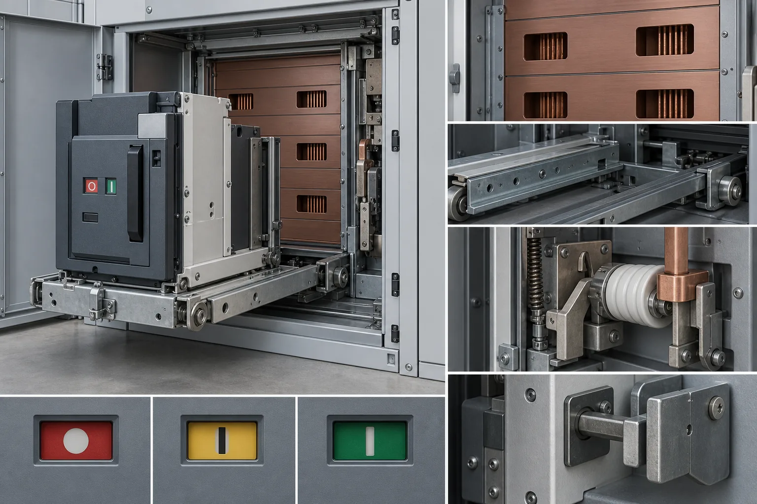
Interlocks prevent an invalid operating sequence. They may be mechanical, electrical, or a combination of both. Shutters and position indicators add another layer of protection and feedback in withdrawable equipment.
Ask practical questions:
- Can the breaker close while the earthing switch is closed?
- Can the device be racked while closed?
- Do the shutters close in the disconnected position?
- Which source-transfer states must be blocked?
- Is paralleling of two sources prohibited?
- Which position signals must reach the relay, PLC, or SCADA system?
A Montreal hospital project used redundant distribution, automatic source transfer, remote supervision, and interlocks to prevent source paralleling. The useful lesson is not to copy that exact arrangement. It is to define the operating philosophy before selecting the interlock hardware.
4. Insulation, enclosure, and cable interfaces
Insulators, barriers, bushings, and contact boxes
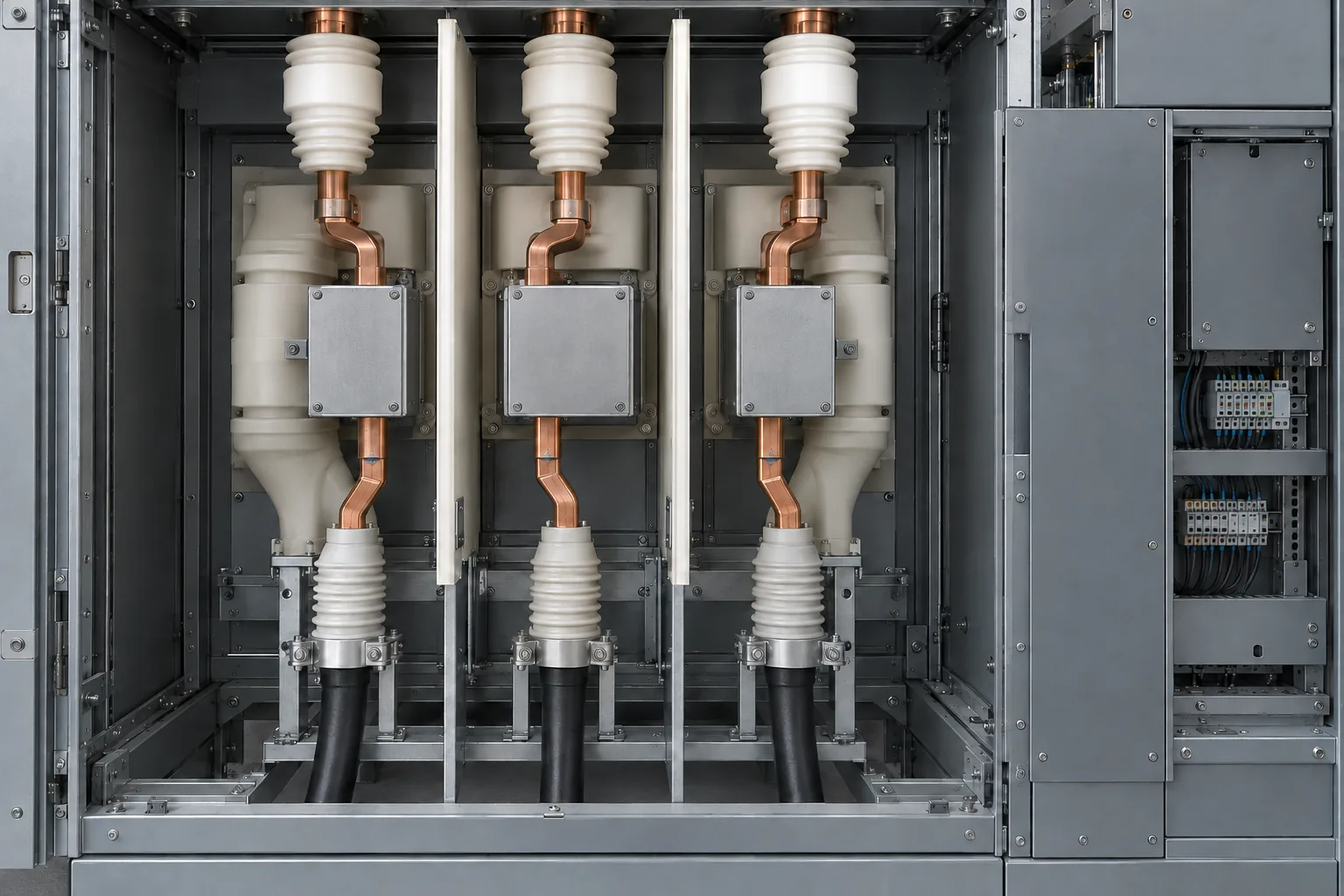
These components keep conductors supported and separated. They also define the path through cabinet walls and between compartments. In air-insulated equipment, the physical air clearances and barriers are part of the design. In gas-insulated equipment, the enclosure and insulating medium create a different boundary.
That difference matters during maintenance, replacement, and testing. A part that looks similar in a photograph may belong to a different insulation system or connection geometry. Confirm the equipment construction, interface dimensions, environmental conditions, and verification requirements with the responsible designer.
Partial-discharge testing makes the point clearly. EA Technology’s GIS material compares detection methods against the construction of the equipment; a method that works for one arrangement should not be assumed to work for every GIS or air-insulated assembly.
Enclosures, compartments, access, and cable entry
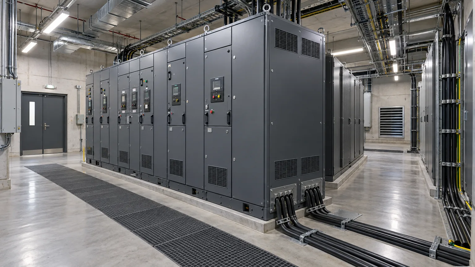
The enclosure affects more than appearance. Doors, barriers, compartments, ventilation, heaters, seals, lifting points, access panels, and cable-entry plates determine how the equipment is installed and maintained. For projects that need a cabinet built around drawings, dimensions, openings, and cable-entry requirements, see custom electrical enclosures from drawings before finalizing the enclosure scope.
Before an RFQ, record whether the assembly is:
- indoor or outdoor;
- front-accessible, rear-accessible, or walk-in;
- installed in a new room or an existing room;
- exposed to dust, humidity, condensation, corrosion, heat, cold, or altitude;
- expected to accommodate future extension;
- connected from the top, bottom, side, or rear.
Fix the cable-entry direction before releasing the enclosure drawing. Then specify the cable glands and gland plates for the planned cables and openings.
Projects such as S&C’s airport switchgear installation, the Fairview hospital renovation, and the BART station retrofit show why cabinet geometry and installation constraints belong beside the electrical rating.
5. How switchgear components work together
Here is the simplest way to picture the system:
- Power enters through an incoming connection.
- Busbars distribute it to a tie or feeder section.
- CTs, VTs/PTs, or sensors measure the electrical condition.
- The relay or trip unit evaluates the measurement.
- A trip or close command travels through the control circuit.
- The mechanism moves the breaker, switch, or contactor.
- The interrupting device opens the current path when required.
- Auxiliary contacts and position indicators report the result.
- The control or communication system records the state or raises an alarm.
This sequence is a functional model, not a universal wiring diagram. Some assemblies integrate protection into the breaker. Others use fuses, contactors, reclosers, or different control architectures. The important point is to keep measurement, decision, operation, interruption, and feedback as separate functions when reviewing a specification.
6. What changes between LV and MV switchgear?
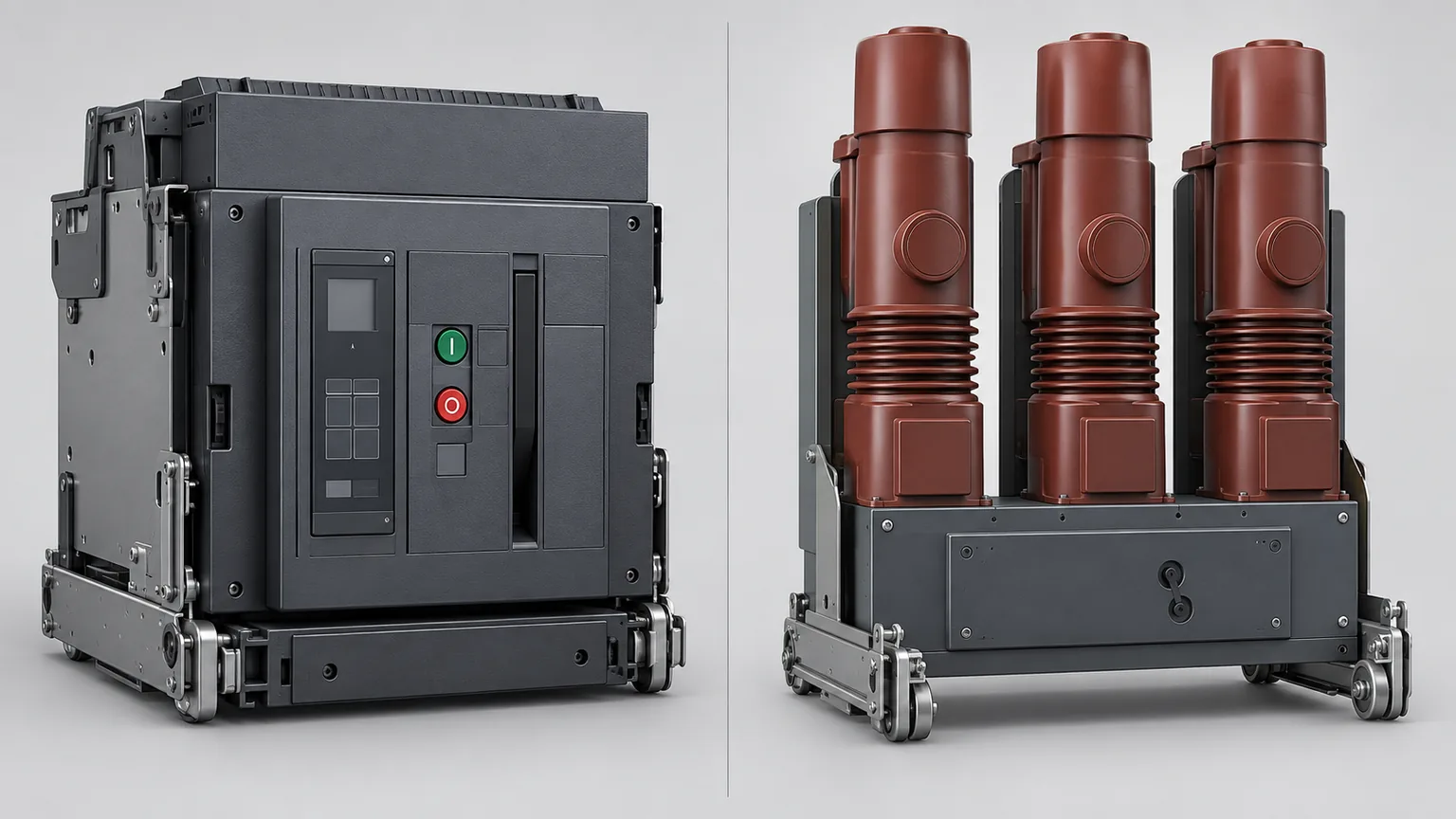
The safest comparison is functional. Do not copy an LV parts list into an MV project.
| Design question | Low-voltage switchgear | Medium-voltage switchgear |
|---|---|---|
| Switching device | Often molded-case or air circuit breakers, fuses, contactors, or combinations | Often vacuum or other MV interrupting devices, load-break switches, fuses, or combinations |
| Protection | May be integrated into a breaker trip unit | Often uses separate relays, CTs/VTs, sensors, or digital devices |
| Primary interface | Busbars, cable terminations, and drawout/stab connections vary by lineup | Primary disconnects, bushings, shutters, cable terminations, and insulation boundaries are central concerns |
| Isolation and grounding | Depends on the assembly and application | Isolation, earthing, position, and interlocking are often central to the operating sequence |
| RFQ emphasis | Frame, interrupting rating, trip functions, busbar connections, accessories, and control wiring | Voltage class, insulation, short-circuit duty, mechanism, measurement scheme, relay logic, cable interface, interlocks, and environment |
Even within LV or MV, fixed and withdrawable designs, AIS and GIS construction, utility and industrial applications, and different maintenance philosophies can change the component arrangement.
For an LV project, also check the switchboard vs panelboard distinction. The assembly name affects what you need to specify; neither term is interchangeable with switchgear.
7. Five component mismatches that trigger redesign or RFQ delays
1. The rating matches, but the geometry does not
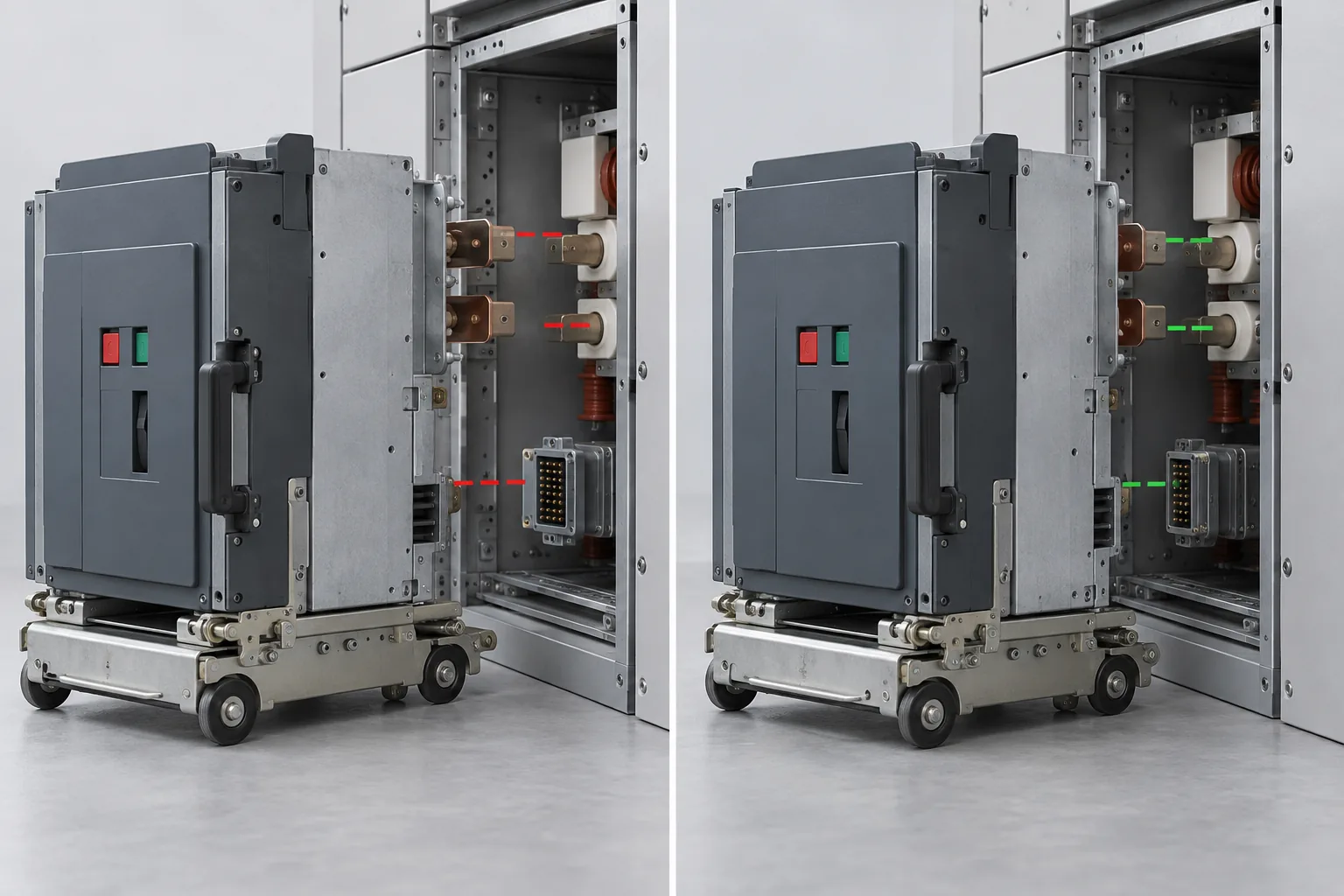
The new device has a similar voltage and current rating, but its primary contacts, busbar connections, mounting points, or cable terminations do not align.
Check usable mounting area, wiring space, and maintenance access with an electrical enclosure sizing review, alongside the original equipment’s interface dimensions.
2. The breaker fits, but the control circuit does not
The trip coil, closing coil, auxiliary contacts, secondary plug, terminal numbering, or control voltage does not match the retained equipment.
3. The relay is treated as a plug-in upgrade
The new relay needs different CT/PT inputs, wiring, settings, communication, or testing. The front-panel function list does not prove compatibility.
4. The interlock is left until the end
The cabinet may be complete on paper but still unsafe or unusable if racking, earthing, source-transfer, shutter, or local/remote interlocks are undefined.
5. The retained scope is never written down
A retrofit may retain frames, cables, busbars, or cabinet structures while replacing selected internal devices. That can reduce site disruption, but only when the retained boundary is measured, documented, and accepted by the responsible designer. Eaton’s switchgear refurbishment case and ABB’s Hafslund Celsio upgrade show why “replace the breaker” is not a complete scope statement.
If retained doors or gland plates need new openings, document how enclosure cutouts affect the finished rating before releasing the change.
8. What information should you include in a switchgear RFQ?
A useful RFQ lets suppliers price the same problem. The checklist combines switchgear RFQ inputs with FAT/SAT acceptance checks. If the project scope is the cabinet around a power-distribution assembly, compare the requirements with custom power distribution enclosures before sending the package.
System scope
- single-line diagram;
- new installation, extension, replacement, or retrofit;
- incomer, tie, and feeder arrangement;
- voltage level and grounding arrangement;
- applicable project specification and jurisdiction.
Electrical duty
- rated voltage and current;
- short-circuit or withstand requirements from the responsible study;
- load types and operating duty;
- source-transfer or paralleling philosophy;
- future extension requirements.
Primary and cable interfaces
- busbar arrangement and connection drawing;
- cable size, termination type, and entry direction;
- phase spacing and connection dimensions;
- components to be retained;
- grounding and bonding points.
Protection, control, and communication
- protection functions and settings responsibility;
- CT/VT/sensor requirements;
- control power and coil data;
- auxiliary contact list;
- interlock matrix;
- local/remote control;
- protocol, point list, alarm list, and network boundary.
Mechanical, environmental, and implementation data
- overall dimensions and access direction;
- room, lifting, transport, and maintenance constraints;
- indoor/outdoor conditions;
- heat, humidity, dust, pollution, altitude, and condensation conditions;
- outage window and temporary-power plan;
- FAT, SAT, installation, commissioning, and handover responsibilities.
An RFQ should name the required designation, not just say “weatherproof”; NEMA and IP enclosure ratings describe different requirements.
Include ambient temperature, equipment heat losses, and humidity conditions so enclosure cooling and condensation control can be reviewed with the cabinet layout.
For retrofit work, add the existing model, nameplate photographs, as-built drawings, measured dimensions, cable and busbar photographs, historical modifications, and a clear list of what must remain in service. A Bristol hospital upgrade encountered additional challenges because the existing switchgear had been modified several times. That detail belongs in the RFQ before the price is finalized.

Frequently asked questions
No. A circuit breaker is one switching or interrupting device. Switchgear is the larger assembly around it, which may include busbars, switches, fuses, measurement devices, protection, control circuits, interlocks, insulation, and an enclosure.
No. The component mix depends on voltage level, switching duty, insulation system, cabinet architecture, protection philosophy, environment, and project scope.
The relay evaluates the measured condition and sends a command. The breaker and its mechanism carry out the physical interruption. The trip circuit connects those functions.
Sometimes. Feasibility depends on the existing geometry, busbars, cables, insulation boundaries, mechanism, control circuit, protection scheme, interlocks, available drawings, and verification plan. Similar ratings alone are not enough.
Send the single-line diagram, voltage and current requirements, short-circuit study inputs, existing equipment information, cable and busbar interfaces, protection and control requirements, environmental conditions, drawings, photographs, and the required installation or outage schedule.
Conclusion
A switchgear component list becomes useful only when every part is tied to a duty and an interface.
- Breakers interrupt.
- Disconnects isolate.
- Busbars distribute.
- CTs, VTs, and sensors measure.
- Relays decide.
- Coils and mechanisms operate.
- Interlocks restrict the sequence.
- Insulation and enclosures maintain the physical boundary.
- Auxiliary and communication circuits report what happened.
If you are requesting a new assembly or replacing components in an existing lineup, do not send only an ampere rating or a preferred model. Send the drawings, measurements, control information, environmental conditions, retained-equipment scope, and project schedule. A supplier can compare and engineer the quote only when the underlying problem is defined.
Planning the enclosure or cabinet scope for a switchgear project? Send the single-line diagram, equipment photos, interface dimensions, cable-entry details, environmental conditions, and retained-scope requirements for review.