
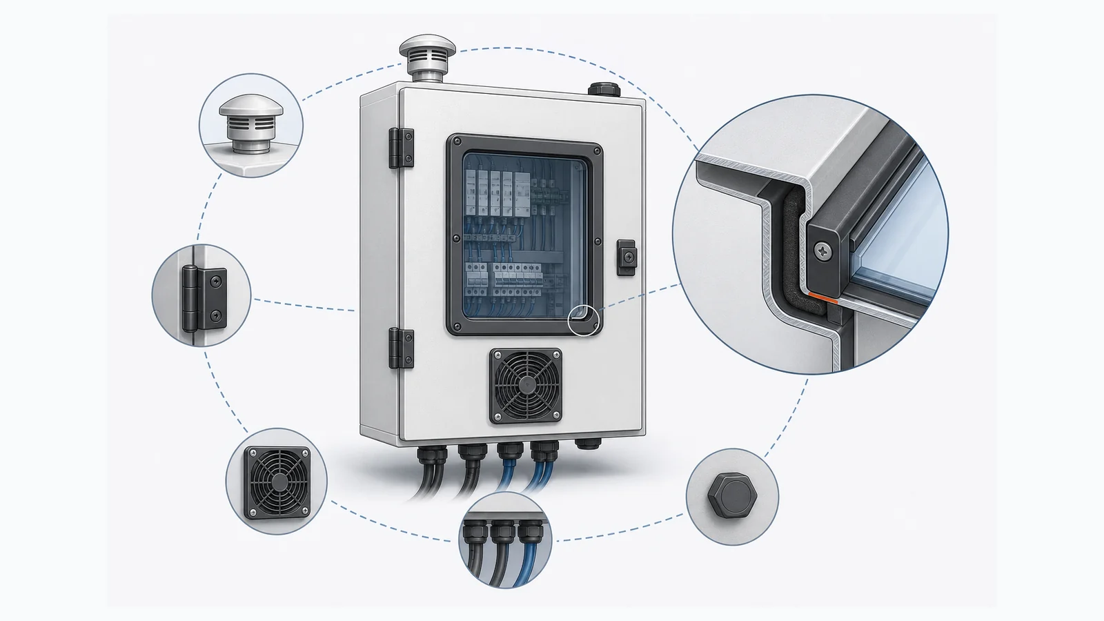

Cut a hole in a rated enclosure and the original rating no longer tells the whole story.
Once an opening is added, the finished boundary depends on five linked items: the hole, edge, seal, component, and evidence. Panel condition, orientation, other penetrations, and installation determine whether those items work together. If any one is undefined, the finished IP or NEMA claim is not ready.
Electrical enclosure cutouts are not minor fabrication details. A burr can cut a gasket. An oversized hole can leave a sealing washer partly unsupported. A thin door can bow around a window frame. A fan can pull humid, dusty air across energized components. One unmatched blanking plug can become the easiest path through the cabinet.

The right question is not, “What rating is printed on the accessory?” It is:
Which Hole, Edge, Seal, Component, and Evidence will prove the finished enclosure rating for this installed configuration?
The 5-Part Cutout Release Check
Use this check before drawing release, accessory substitution, or any field modification:
- Hole: size, tolerance, position, corner radius, edge distance, and panel thickness.
- Edge: burrs, chips, flatness, exposed metal, and coating repair.
- Seal: gasket, O-ring, sealing modules, compression path, and spare openings.
- Component: exact order code, mounting direction, panel-thickness range, fasteners, cable, filter, or cooling hardware.
- Evidence: component scope, inspection record, enclosure test, third-party report, or customer approval required by the project.
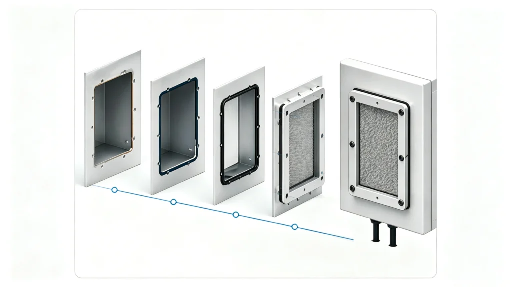
A rated enclosure plus a rated accessory is not proof of the finished assembly. Check the hole, edge, seal, component, and evidence.
Use the model when a drawing is ready for release, an accessory is still TBD, a field hole is requested, or a supplier relies on a component IP/NEMA statement.
How Electrical Enclosure Cutouts Change Finished Protection
Every opening changes at least one part of the protection boundary:
| Opening | What changes |
|---|---|
| Viewing or infrared window | A solid door becomes a framed transparent panel with a perimeter seal and new structural load path |
| Filter fan and outlet | The enclosure becomes an open-air system that admits ambient air through two filtered openings |
| Pressure-equalization vent | The enclosure gains a controlled gas path whose performance depends on membrane condition and mounting position |
| Cable gland or modular transit | The seal now depends on the cable, gland or modules, plate, spare positions, and compression |
| Air conditioner or heat exchanger | A large panel cutout carries equipment weight, a perimeter gasket, fasteners, air paths, and possibly condensate |
| Field hole or knockout | The as-built enclosure departs from the released drawing and needs edge treatment, sealing, inspection, and record control |
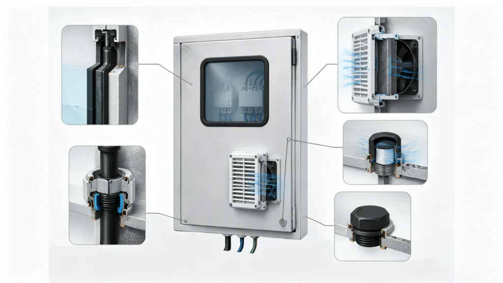
Use a component rating to screen options; do not use it as proof of the finished enclosure rating.
The Rating Belongs to the Installed Configuration
IEC 60529 defines the IP Code. ANSI/NEMA 250 addresses enclosure Types for enclosures installed and ready for use. The systems are not interchangeable, and a conversion chart does not prove compliance for a specific assembly. For the practical distinction between IP65 and IP66 enclosure test differences, keep the same boundary rule: evaluate the installed configuration, not an isolated label.
| Claim | Covers | Does not prove |
|---|---|---|
| Empty enclosure rating | Documented unmodified enclosure | Performance after new enclosure penetrations or accessories |
| Accessory rating/evaluation | Component within stated conditions | Performance of the full door, wall, plate, cable entry, or enclosure |
| Finished-configuration evidence | Defined enclosure with specified openings and components | Other variants, thicknesses, orientations, field changes, or service conditions |
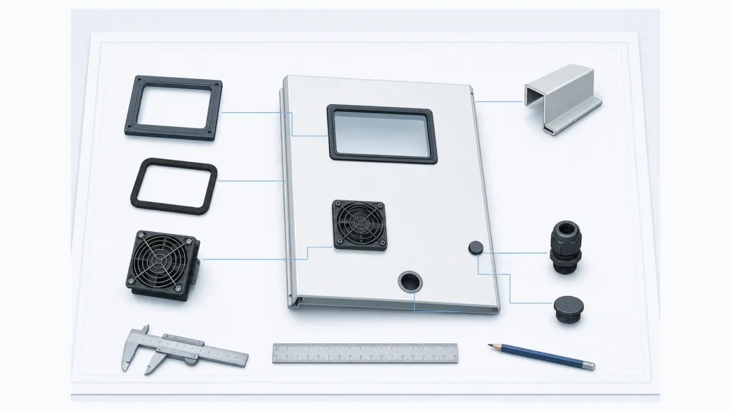
UL Solutions’ environmental-rated accessory guidance covers items such as window kits, filter-fan kits, rain hoods, and hole plugs. Stay within the stated scope; still review the cutout, mounting surface, other penetrations, and end product.
Manufacturer-specific restrictions still apply. Listed equipment or accessory systems may restrict field holes, substitute parts, panel thickness, or mounting position. Follow the project documents, manufacturer instructions, and applicable evaluation scope.
Four failure paths, mapped to the five-part check
Hole + Edge: Large openings remove stiffness. Poor location, burrs, chips, paint ridges, or bare steel can damage the sealing land.
Seal: A folded gasket, loose locknut, wrong cable range, or unloaded corner can form a continuous ingress path.
Component: Fans admit air; vents exchange gas; cooling units add weight, air circuits, and condensate. The component changes the environmental mechanism.
Evidence: A field change can move the enclosure outside the released drawing or evaluated configuration. Recheck the claim when the part, installation, or proof changes.
Windows and Inspection Ports: Treat the Window as Part of the Door
An electrical enclosure window is not a transparent accessory floating inside a hole. It is a door assembly: panel, cutout, frame, transparent insert, gasket, clips or fasteners, and internal clearance.
The opening can also change door stiffness. If the panel bows as the frame is tightened, one side of the gasket may carry more compression than the other. UV, cleaning chemicals, abrasion, and heat can degrade the transparent material or seal even when the frame remains attached.
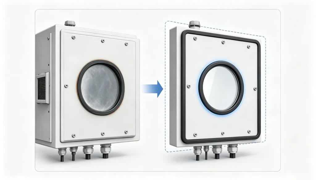
Case: Vandolah Power replaced the complete panel
Situation: The IRISS case involving Vandolah Power describes factory-installed viewing windows on an 18 kV, 8000 A generator breaker that became opaque after long-term UV exposure. Once the window could no longer support clear inspection, the issue was no longer just cosmetic; the inspection interface itself had become unreliable.
Because: The window was part of a working door assembly exposed to UV and inspection demands. Treating the problem as a simple insert replacement would leave the existing cutout, panel stiffness, fastening method, gasket land, and inspection purpose unreviewed.
So: The reported solution used a complete replacement panel with custom inspection windows instead of forcing a generic accessory into the existing opening. That decision reduced the risk of carrying an unsuitable window and an unknown door interface into the next service cycle.
How to improve: Before releasing a replacement or new door, freeze the exact window model and current cutout drawing. Then verify panel material, thickness, flatness, edge distance, remaining stiffness, continuous gasket land, clip or fastener engagement, tool access, internal clearance, and exposure to UV, chemicals, impact, temperature, and cleaning. If those conditions do not match, redesign the panel rather than adapting the hole by assumption.
Release checks:
- Decide whether the existing panel can be safely adapted or should be replaced.
- Require evidence for the finished window-and-door assembly, not only the window component.
- Do not transfer the source case outcome to another IP or NEMA claim.
Fans and Filter Openings: A Fan Makes the Enclosure Open to Ambient Air
A fan is not a sealed cooling device. It pulls outside air—and whatever that air carries—through the cabinet.
Approve an enclosure fan cutout only when four conditions are met:
- Air is allowed: ambient dust, humidity, salt, oil mist, and corrosive gas are acceptable.
- Ambient is cooler: outside air remains below the required internal temperature.
- Airflow is proven: fan, outlet, filters, guards, ducts, and layout deliver enough flow at real resistance. Free-air CFM is not the installed working point.
- Assembly is acceptable: openings, gaskets, orientation, rain path, filter condition, and maintenance support the finished requirement.
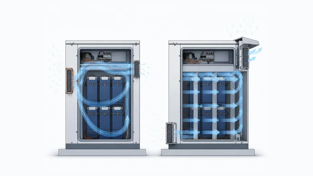
See electrical enclosure filter fans for heat load, working point, commissioning, and maintenance.
Case: an outdoor battery cabinet had to balance airflow and waterproofing
Situation: The outdoor lithium-battery cabinet case describes a cabinet whose width constraint restricted heat removal. The cabinet still had to work in an outdoor environment, so the design problem combined limited internal space, heat dissipation, and exposure to rain and contaminants.
Because: The cabinet envelope and internal arrangement controlled the available heat path. A fan or vent added after the layout was fixed would not create the missing space, and an open-air opening could introduce a new weather and maintenance boundary.
So: The reported design response changed the enclosure dimensions and internal arrangement to improve airflow while addressing outdoor exposure. The improvement was therefore a layout decision first and a component decision second.
How to improve: Set the thermal strategy before finalizing cutouts: decide whether ambient air is allowed, define the heat load and required airflow, and select filtered ventilation, a heat exchanger, or closed-loop cooling accordingly. Then place inlet and outlet openings with a defined rain path, filter service path, gasket, fastener pattern, and contamination limit. Review dust, water, salt, oil mist, temperature, and maintenance together.
Release checks:
- Do not use “add a fan” as a substitute for cabinet thermal-layout work.
- Treat the fan, outlet, filter, guard, gasket, and service access as one installed arrangement.
- The source case supports the design sequence; it does not prove another cabinet rating.
Do not group every vented component under “cooling opening”
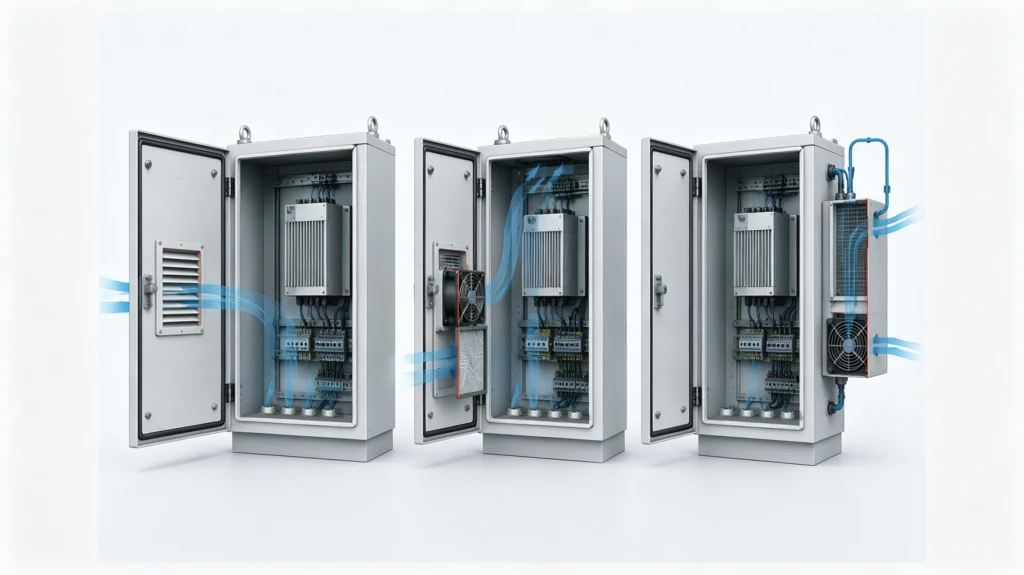
| Method | Ambient air enters the equipment space? | Cutout controls |
|---|---|---|
| Filter fan and outlet | Yes | Inlet/outlet position, filter, rain path, installed airflow, gasket |
| Membrane vent | Gas passes through membrane | Flow, wetting, fouling, drainage, orientation |
| Air-to-air heat exchanger | No direct mixing | Large cutout, gasket, two air paths, panel load |
| Enclosure air conditioner | No direct mixing in normal operation | Cutout, gasket, condensate, controls, heat rejection |
| Air-to-water heat exchanger | No ambient-air mixing | Panel interface, piping, leak/condensate risk, controls |
Closed-loop cooling avoids direct air exchange but still creates a loaded gasketed interface. Review thermal and weather paths together with the outdoor electrical enclosure design checklist.
Pressure Vents: Use a Controlled Path Instead of Waiting for a Weak Seal to Leak
Air inside a sealed housing expands as it heats and contracts as it cools. Repeated pressure cycles load the door gasket, cable entries, windows, and plugs. If the enclosure cannot equalize through a designed path, humid air may enter through whichever seal gives way first.
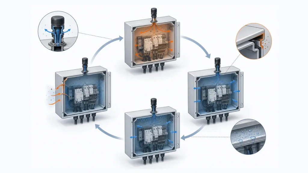
Case: temperature cycling contributed to condensation in an IP67 housing
Situation: The Gore/Laird smart-antenna case describes an IP67 thermoplastic housing exposed to rapid temperature changes. The housing had to manage the pressure and moisture consequences of repeated thermal cycling while remaining exposed to weather.
Because: Air inside a sealed housing expands when heated and contracts when cooled. Repeated pressure differentials load the door, cable, window, and plug interfaces; if there is no designed equalization path, humid air can enter through the weakest seal and later condense on a cooler internal surface.
So: The reported response used a snap-in protective vent on a vertical surface away from direct driving rain and snow. The vent created a controlled pressure path while its position reduced direct wetting. The result belongs to that housing, vent, mounting, and exposure configuration—not automatically to another enclosure.
How to improve: Specify the vent as an interface, not a hole: required equalization flow, approved mounting-hole size, panel thickness, gasket and retention method, vertical or other permitted orientation, direct-spray exposure, drainage, dust and oil fouling, and maintenance limits. Also decide whether the vent solves pressure only or forms part of a wider condensation-control strategy. Request evidence for the complete housing when a rating claim is required.
Release checks:
- Separate pressure equalization from cooling and from general moisture protection.
- Keep the vent away from pooling water and direct driving spray unless the design evidence allows it.
- Do not use the IP67 statement in the source as a transferable rating for another housing.
Cable Entries: One Hole Creates Three Sealing Interfaces
An electrical enclosure cable entry is not defined by thread size and quantity. The cable, gland or modules, plate, and enclosure form one assembly.
A removable gland plate creates three seals:
- Cable to gland: actual cable OD, jacket condition, sealing range, and compression.
- Gland to plate: hole, washer/O-ring, locknut, panel thickness, burrs, coating, and flatness.
- Plate to enclosure: perimeter gasket, plate stiffness, fastener spacing, and compression.
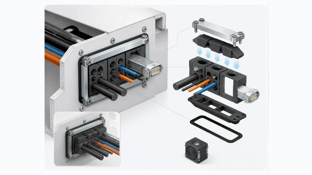
A gland can be correctly tightened and still leak if its washer bridges a burr, the cable is scored or side-loaded, the plate bows, or a spare plug does not match the hole. See cable glands and gland plates for the full diagnostic.
Case: Ceneri Tunnel cabinets treated cable entry as a system
Situation: The Roxtec case for the AlpTransit Ceneri Tunnel describes pressure-tight control cabinets exposed to dirt, moisture, heat, and pressure or suction loads from high-speed trains. The cabinets also had to accept cables and pre-terminated connectors through controlled entry points.
Because: The cable entry had more variables than a thread size: cable outside diameter, connector shape, frame or plate geometry, module selection, compression, bend radius, and the tunnel environment all affected the boundary. A fixed list such as “ten M25 holes” would not define those interfaces.
So: The reported approach used modular seals that could be arranged around the cables and pre-terminated connectors. That made the entry adaptable while keeping the opening, frame, modules, and compression under one design logic. The source’s reported test and IP65 statements apply only to its stated project configuration.
How to improve: Release the entry as a complete assembly. Put the cable schedule, actual cable OD and construction, connector dimensions, frame or plate, hole and tolerance, module arrangement, compression method, spare positions, support and bend radius, gasket details, installer, inspection method, target protection, and evidence requirement on the RFQ or drawing. Recheck the perimeter seal whenever the plate or module layout changes.
Release checks:
- Match the sealing range to the actual cable, not the nominal gland thread.
- Control spare openings and future cable changes before installation.
- Keep project-specific test or IP statements bounded to the documented assembly.
Field Holes: Stop the Change Before the Drill Reaches the Door
Field holes in electrical enclosures carry more risk than inaccurate diameter. A change may use an old drawing, hit a stiffener, cross the door-gasket land, or install a component outside its panel-thickness range.
The evidence is physical: chips inside the cabinet, a sharp edge under a gasket, bare steel, a tilted plug, or sealant covering an uncontrolled gap. Once the hole is added, the released drawing no longer matches the enclosure.
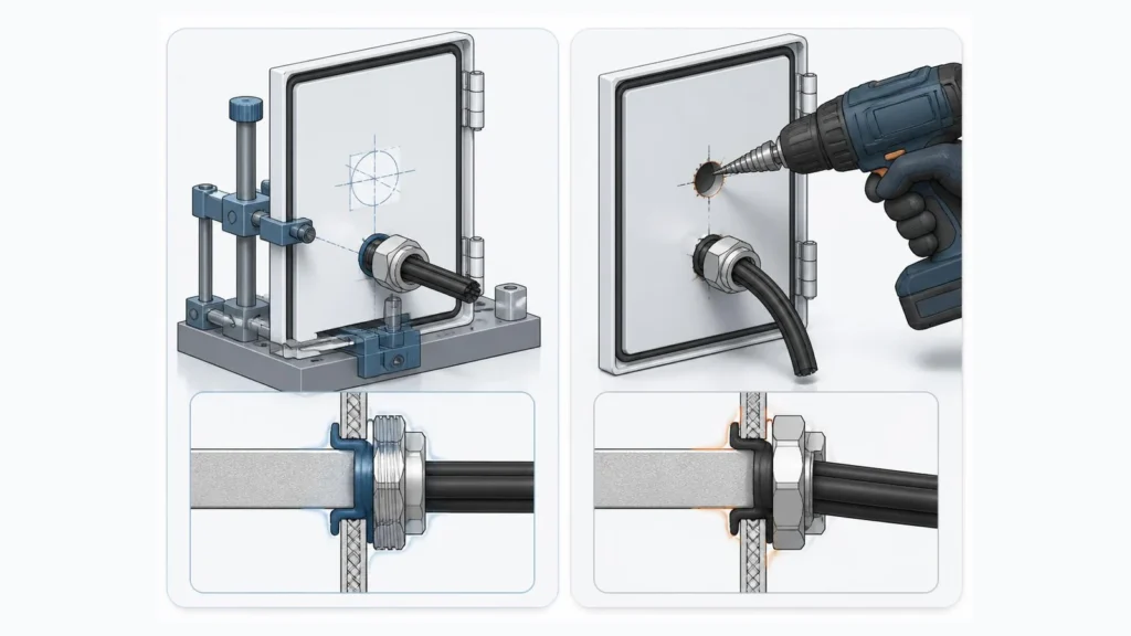
Case: automated modification improved repeatability, not rating evidence
Situation: The AMtec/nVent HOFFMAN ModCenter case describes late design changes, manual modification, outsourced cutting, and a move toward CAD-driven automated machining. The underlying problem was not only cutting speed; it was the repeatability and revision control of repeated panel changes.
Because: Late changes can send an old drawing to the shop, place a hole over a stiffener or gasket land, create inconsistent dimensions, leave chips or burrs, damage the coating, or produce no reliable as-built record. A clean-looking hole does not show that the correct component, seal, or approved revision was used.
So: CAD-driven automated machining improved repeatability and change control in the reported case. It did not, by itself, prove that a modified enclosure retained its previous rating. The machining method solved a manufacturing-control problem; the finished-rating question still required component, seal, finish, installation, and evidence review.
How to improve: Freeze the revision before cutting and link the approved CAD file to the work order. Use first-article dimensional inspection, controlled deburring and chip removal, exposed-edge treatment, component-fit verification, gasket-compression review, fastener or locknut checks, and an as-built record. For repeated variants, decide whether factory modification or a purpose-built body is the lower-risk route before the purchase order.
Release checks:
- Separate machining repeatability from finished-rating evidence.
- Record the exact cutout revision and installed component order code.
- If the field change alters the released configuration, define whether re-evaluation or new acceptance evidence is required.
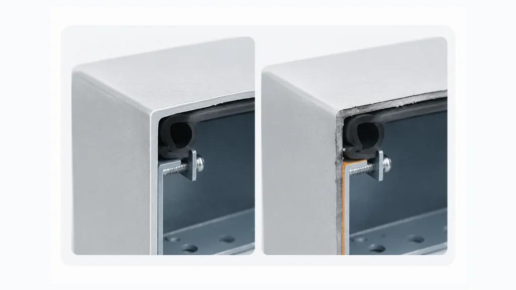
Use this change-control sequence
- Identify: enclosure, opening purpose, drawing revision, and reason.
- Review: exact component, cutout, panel, stiffeners, gasket land, wiring, and clearance.
- Decide: whether existing evidence applies, new evidence is required, or the claim changes.
- Instruct: size, tolerance, tool, chip control, deburring, edge repair, seal, hardware, and orientation.
- Verify and record: inspect the first article, then update the drawing, BOM, as-built file, maintenance list, and acceptance evidence.
For repeated custom enclosure openings, decide the factory method and evidence before the purchase order instead of recreating the same change as a field hole.
Factory cutting is easier to repeat and inspect than an improvised site cut. It is still only one part of the finished enclosure rating.
Use an Opening Risk Matrix Before Drawing Release
Approve each opening by its failure mechanism, not by its product category.
| Opening type | Main failure mechanism | Details that control the result | Evidence to request |
|---|---|---|---|
| Viewing or infrared window | Framed panel and perimeter seal | Cutout, panel stiffness, gasket, fasteners, UV/chemical exposure | Component scope, installation drawing, finished-assembly requirement |
| Filter fan or membrane vent | Open airflow or controlled pressure exchange | Air quality, working point or vent flow, rain path, fouling, orientation | Performance data, cutout drawing, environmental scope, commissioning criteria |
| Cable gland | Cable seal plus wall/plate interface | Cable OD and jacket, washer/O-ring, hole, panel thickness, side load | Exact gland range, accessories, installation instructions |
| Modular transit or gland plate | Compressed modules or removable gasketed panel | Frame fit, module selection, plate flatness, perimeter gasket, spare positions | System drawing, cable schedule, gasket specification, inspection plan |
| Air conditioner or heat exchanger | Large loaded panel interface | Reinforcement, gasket, fasteners, condensate, service orientation | Hardware drawing, thermal inputs, condensate plan, rating scope |
| Field-drilled hole | Uncontrolled design change | Revision, geometry, chips, burrs, coating repair, wrong hardware | Approved change, work instruction, as-built record, re-evaluation plan |
Finished-Configuration Review: 12 Checks
The five-part check is the memory tool. The 12-point list is the release record.
Do not release the enclosure while any item remains undefined:
- Requirement: exact IP Code, NEMA Type, customer specification, test, or market requirement.
- Evidence: supplier declaration, component certification, enclosure test, end-product evaluation, third-party report, or customer witness point.
- Components: manufacturer, order code, material, seal, accessories, and document revision.
- Drawings: current cutout, installation, enclosure, and component drawings.
- Panel: material, thickness, flatness, stiffness, edge distance, and internal clearance.
- Machining: dimensions, corner radii, tolerance, chip control, deburring, and exposed-edge treatment.
- Seal stack: every gasket, washer, O-ring, module, thread, plug, and perimeter joint.
- Retention: clips, screws, locknuts, fastener spacing, engagement, and tightening method.
- Exposure: rain, washdown, dust, oil, salt, chemicals, UV, pressure, condensation, and cable load.
- Other penetrations: unused holes, drains, locks, hinges, seams, door gaskets, and spare entries.
- Service condition: installer, inspection method, filter or seal replacement, and control of future field changes.
- Acceptance record: dimensional report, photos, visual inspection, airflow or thermal check, ingress test, or third-party evidence as required.
If the exact accessory is still “TBD,” the enclosure cutout rating is also TBD.
What to Put in the RFQ
A useful RFQ follows the same five-part check. Outside dimensions alone are not enough.
| Check | Required RFQ information |
|---|---|
| Hole | Opening ID, purpose, coordinates, size, tolerance, corner radius, panel material, thickness, and drawing revision |
| Edge | Cutting process, chip control, deburring, surface preparation, coating sequence, and corrosion-repair requirement |
| Seal | Gasket/O-ring/module details, sealing washers, gland-plate perimeter, spare positions, and compression method |
| Component | Exact model and order code, data sheet, CAD, cutout drawing, fasteners, orientation, cable schedule, or cooling hardware |
| Evidence | Target IP Code or NEMA Type, applicable standard, inspection photos, first-article report, ingress test, third-party report, or witness point |
| Environment and scope | Indoor/outdoor exposure, rain, washdown, dust, oil, salt, chemicals, UV, temperature, humidity, altitude, installation owner, and maintenance responsibility |
| Quantity and change control | Prototype, batch quantity, variants, approved drawing authority, field-hole restrictions, and as-built update responsibility |
FN can review enclosure geometry, approved cutouts, cable-entry provisions, mounting interfaces, material, finish, gasket paths, and manufacturing requirements within the agreed scope. Cooling performance, electrical design, field installation, complete-system compliance, and third-party testing remain with the responsible parties unless separately defined and verified.
For custom enclosure openings, send the Hole, Edge, Seal, Component, and Evidence inputs with the project drawing.
Frequently Asked Questions
Does an IP66-rated accessory make the complete enclosure IP66?
No. The result still depends on the accessory scope, cutout, panel, seal, hardware, orientation, other penetrations, and installation.
Does adding a viewing window always reduce the enclosure rating?
Not automatically. A compatible window may support a defined target in the specified panel and configuration, but the modified door remains an assembly.
Can a filter fan be used on an IP- or NEMA-targeted enclosure?
Only when open-air cooling suits the environment and the complete fan/outlet arrangement supports the requirement. Check air quality, installed airflow, filters, gaskets, rain path, orientation, and maintenance.
Does an IP68 cable gland make the whole enclosure IP68?
No. Cable-to-gland, gland-to-wall/plate, plate perimeter, spare positions, routing, orientation, and installation remain in the boundary.
Can an unused field hole be closed with a plug?
Only when plug, hole, panel thickness, seal, material, installation, and environmental scope match. Tape, improvised washers, and undocumented sealant are not rating evidence.
Should enclosure cutouts be made before or after coating?
For powder-coated panels, factory cutouts are commonly made before finishing so edges can be deburred, cleaned, and coated. Post-coating holes need chip control, deburring, sealing-surface preparation, and corrosion repair.
Who owns the finished rating after a field modification?
The project documents should name the responsible party for the standard, approved component, installation, evidence, drawing update, and acceptance. The empty-enclosure statement does not automatically cover an uncontrolled field change.
Final Position
Do not approve a cutout by matching the rating on an empty enclosure with the rating on an accessory data sheet. Those are two component statements, not proof of the installed assembly.
Approve what will actually be built:
Hole → Edge → Seal → Component → Evidence
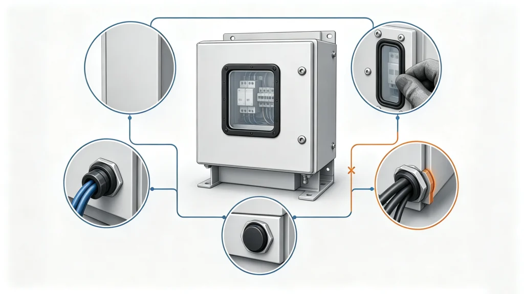
Settle electrical enclosure cutouts before drawing release, not after the cabinet reaches the site. If one of the five items is undefined, the finished enclosure rating is undefined too.