
Outdoor Telecom Enclosures for Equipment, Fiber and Power
FN makes outside-plant cabinet bodies. Start with the rack and equipment layout, heat load, fiber and copper entry, power and battery zones, mounting method and service access. Selected cooling and power systems remain with the integrator.
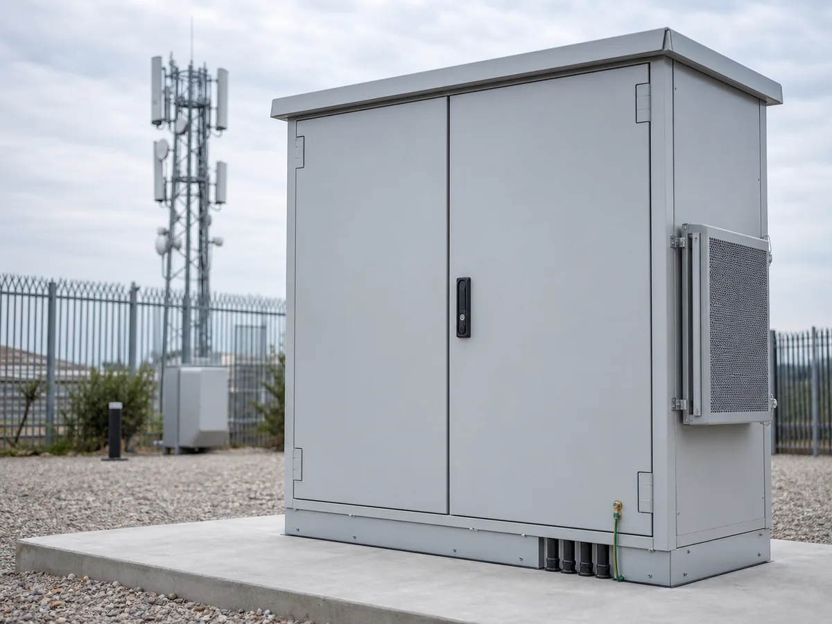
01 / SYSTEM POSITION
How the cabinet body fits an outside-plant site
The cabinet body provides agreed rack space, cable entry, battery and power zones, mounting points, physical-security features and service access. Cooling hardware openings follow the selected system design.
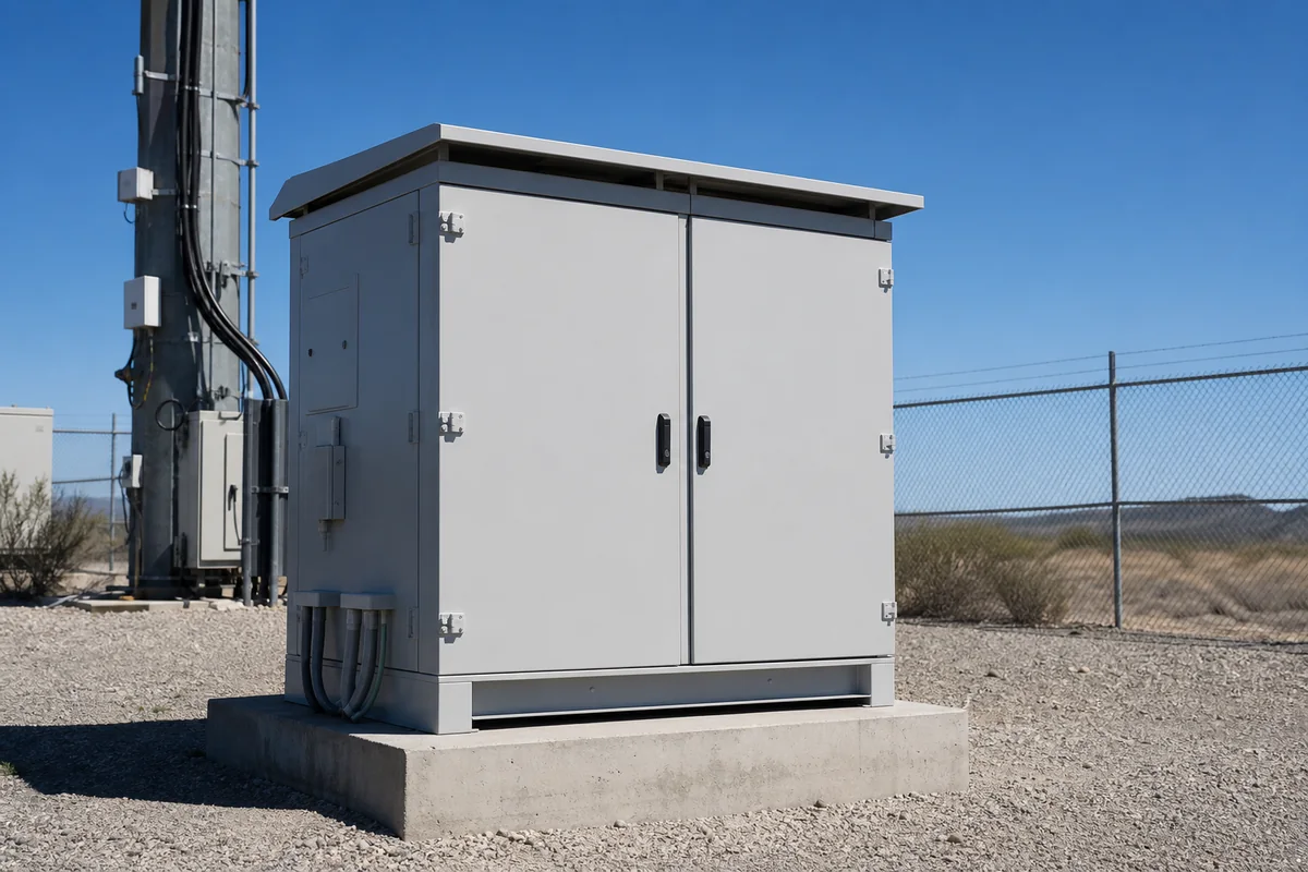
Five Outside-Plant Mechanical Interfaces
CABINET INTERIOR
Equipment + Rack
19-inch rails, shelves, backplate, depth and service clearance.
Fiber + Copper
Entry plates, bend radius, slack storage and separation.
Power + Battery Zone
Battery compartment, power equipment supports and cable paths.
SITE + ENVIRONMENT
Thermal + Condensation
Solar load, cooling opening, drainage and service side.
Mounting + Maintenance
Pole, wall, pad or plinth interface; door swing and technician access.
Site-interface diagram · not a network, electrical or thermal design
FN manufacturing scope
- Cabinet body, doors, rack or mounting provisions, shelves, partitions and defined structure.
- Approved openings and brackets for cooling, cable entry, antennas or accessories.
- Pole, wall, pad, plinth or foundation interfaces in the released drawing.
- Agreed dimensional, visual, hardware and packing records.
Boundary: Network architecture, radio or transmission performance, equipment selection, wiring, battery system, cooling capacity, site civil work, commissioning and complete-site certification remain with their responsible parties.
02 / TYPICAL CONFIGURATIONS
Three Telecom Cabinet Routes From Small Sites to Multi-Zone Cabinets
Mounting method, equipment depth, heat, fiber volume, battery requirements and field access determine the cabinet route.
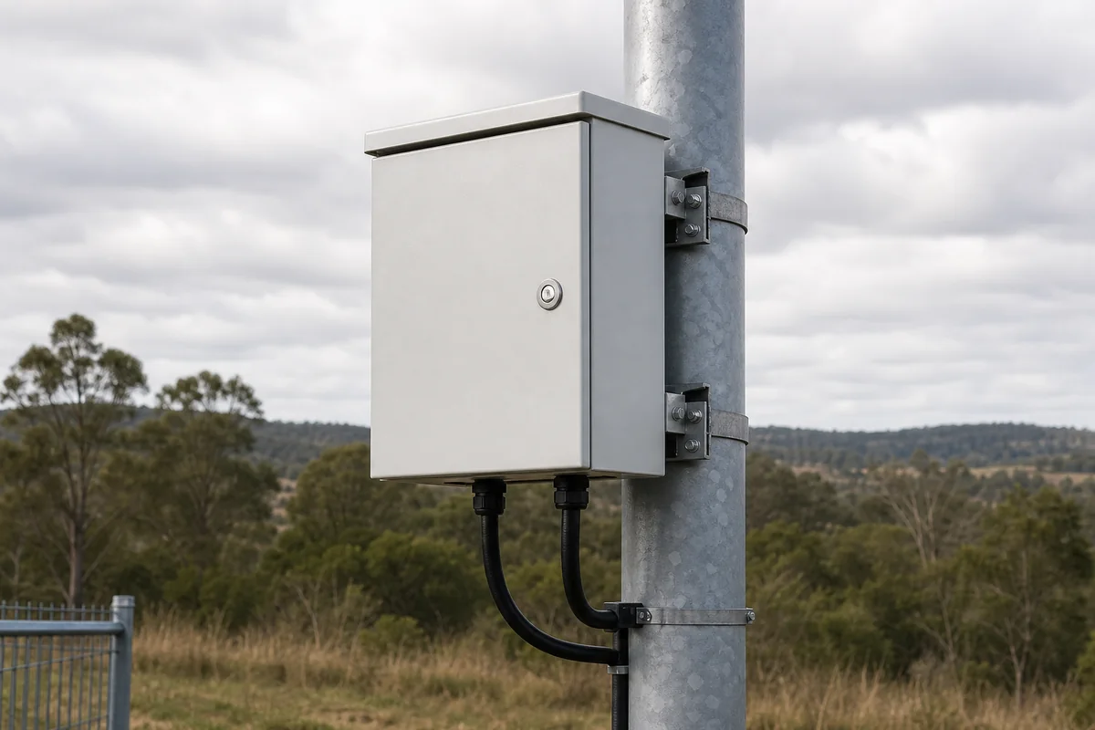
Pole / Wall-Mounted Telecom Cabinet
Compact outside-plant bodies for passive or active equipment at constrained sites.
- Pole or wall bracket interface
- Equipment depth and door projection
- Bottom cable entry and drip path
- Technician reach and service side
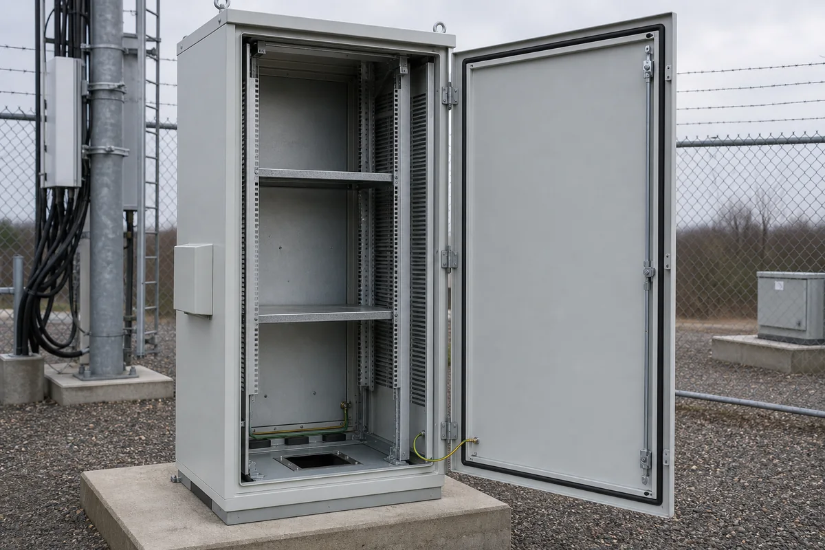
Outdoor Rack Equipment Cabinet
Pad- or plinth-mounted cabinets using rack rails, shelves and thermal hardware.
- Rack unit and depth schedule
- Heat load and solar exposure
- Fiber/copper entry zones
- Front/rear maintenance access
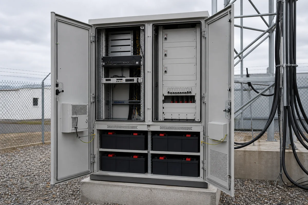
Multi-Compartment Power + Battery Cabinet
Larger cabinets separating communications, power and battery functions.
- Compartment and partition plan
- Battery weight and ventilation concept
- Cable crossover control
- Door sequence and replacement path
03 / FAILURE MODES
Outside-Plant Failures That Begin as Missing Mechanical Inputs
Weatherproof language alone does not resolve solar gain, condensation, fiber routing, battery zones, mounting and field-service geometry.
Solar exposure and heat load are not declared
Consequence: Cooling hardware or cabinet volume changes late.
Mechanical decision: Roof treatment, shade, openings, service side and internal space.
Required input: Site orientation, solar exposure, heat-load table and cooling concept.
Condensation and drainage path are ignored
Consequence: Moisture can collect around equipment or cable entry.
Mechanical decision: Drip path, drainage, bottom geometry and internal airflow provisions.
Required input: Climate profile, temperature cycling and moisture-control concept.
Fiber bend radius is checked after layout
Consequence: Fiber routing conflicts with doors, racks or power cables.
Mechanical decision: Entry position, slack zone, cable managers and usable depth.
Required input: Fiber count, connector type, bend radius and routing sketch.
Battery compartment is added late
Consequence: Weight, ventilation, door and cable routing require redesign.
Mechanical decision: Partition, support, access, vent provisions and base loads.
Required input: Battery model, weight, dimensions and system requirements.
Door swing and maintenance space are assumed
Consequence: Technicians cannot access filters, racks or connectors.
Mechanical decision: Hinge side, removable panels, service side and clearances.
Required input: Site plan, adjacent obstructions and maintenance sequence.
Pole, pad or foundation interface is provisional
Consequence: Mounting holes, base geometry or site assumptions conflict.
Mechanical decision: Brackets, plinth, anchors and cabinet orientation.
Required input: Approved site mounting drawing and structural responsibility.
04 / DESIGN REVIEW MATRIX
Six telecom interfaces to review before fabrication
Each interface should be linked to a site drawing, equipment schedule or responsibility note.
Equipment / Rack
Interface: Rack units, rail spacing, depth, shelves, backplate and replacement clearance.
Review question: Which equipment models and future positions are reserved?
Release evidence: Equipment list + rack elevation + service envelope.
Thermal / Moisture
Interface: Heat load, solar exposure, cooling hardware, drainage and condensation concept.
Review question: Who selects and validates the complete thermal solution?
Release evidence: Heat-load table + site climate + hardware drawing.
Fiber / Copper
Interface: Entry, bend radius, slack management, connector access and segregation.
Review question: How many fibers and cables enter from each direction?
Release evidence: Cable schedule + routing and entry drawing.
Power / Battery
Interface: Power equipment, batteries, supports, partitions, vents and cable crossing.
Review question: Are battery type, weight and service requirements frozen?
Release evidence: Equipment data + compartment and support drawing.
Site / Maintenance
Interface: Pole, wall, pad or foundation; door swing, security and technician access.
Review question: What site obstructions and mounting loads apply?
Release evidence: Site plan + mounting drawing + access sequence.
Security / Public Interface
Interface: Locks, hinges, exposed fasteners, handles and access-control provisions.
Review question: Which physical-security requirements are specified?
Release evidence: Customer security specification + approved hardware list.
05 / CONFIGURATION ROUTES
Select the Cabinet Platform From Site Conditions and Interface Density
A small pole cabinet, a rack cabinet and a multi-compartment outside-plant cabinet require different structures and review packages.
Standard Outdoor Cabinet
Use when a catalog body fits equipment, mounting, climate and cable-entry conditions without structural changes.
- Fast comparison route
- Confirm usable depth and accessories
- Customer adapts most internal equipment
Modified Rack / Site Cabinet
Use when a known body needs rack rails, shelves, cable plates, cooling openings or site-specific mounting.
- Controlled modification drawings
- Good for repeat site variants
- Interface review still required
Fully Custom Multi-Zone Cabinet
Use for unusual depth, batteries, multiple compartments, integrated plinths or constrained maintenance access.
- Project-specific body and structure
- Complete five-interface review
- First-article CTQs and variant control
06 / BEFORE QUOTATION
What to confirm for an outdoor telecom cabinet quote
The quote should distinguish equipment, site and environmental inputs that are approved from those still provisional.
Quote the rack, cable and site interfaces
FN uses rack, heat, cable, power and site information to define body geometry, doors, mounting features, openings, partitions and requested inspection records.
Equipment & Rack
Models, rack units, depth, shelves, backplate, weight and replacement path.
Heat, Solar & Moisture
Heat load, orientation, climate, cooling concept, drainage and condensation assumptions.
Fiber & Cable
Counts, bend radius, slack, entry zones, connectors and power separation.
Power & Battery
Power devices, battery model, weights, compartment, ventilation interface and access.
Site & Security
Pole/pad/wall/foundation, door swing, public exposure, locks and obstructions.
Commercial & Quality
Quantity, site variants, target market, customer specification, CTQs, packing and date.
Gate 01 · Site Input Review
Confirm mounting, orientation, climate, security and maintenance access.
Gate 02 · Equipment Interface Review
Align rack, shelves, depth, batteries and replacement paths.
Gate 03 · Thermal + Cable Review
Coordinate openings, fiber/copper routes, drainage and service side.
Gate 04 · Drawing Release
Freeze revision, critical dimensions, hardware and inspection points.
Mechanical Details to Review
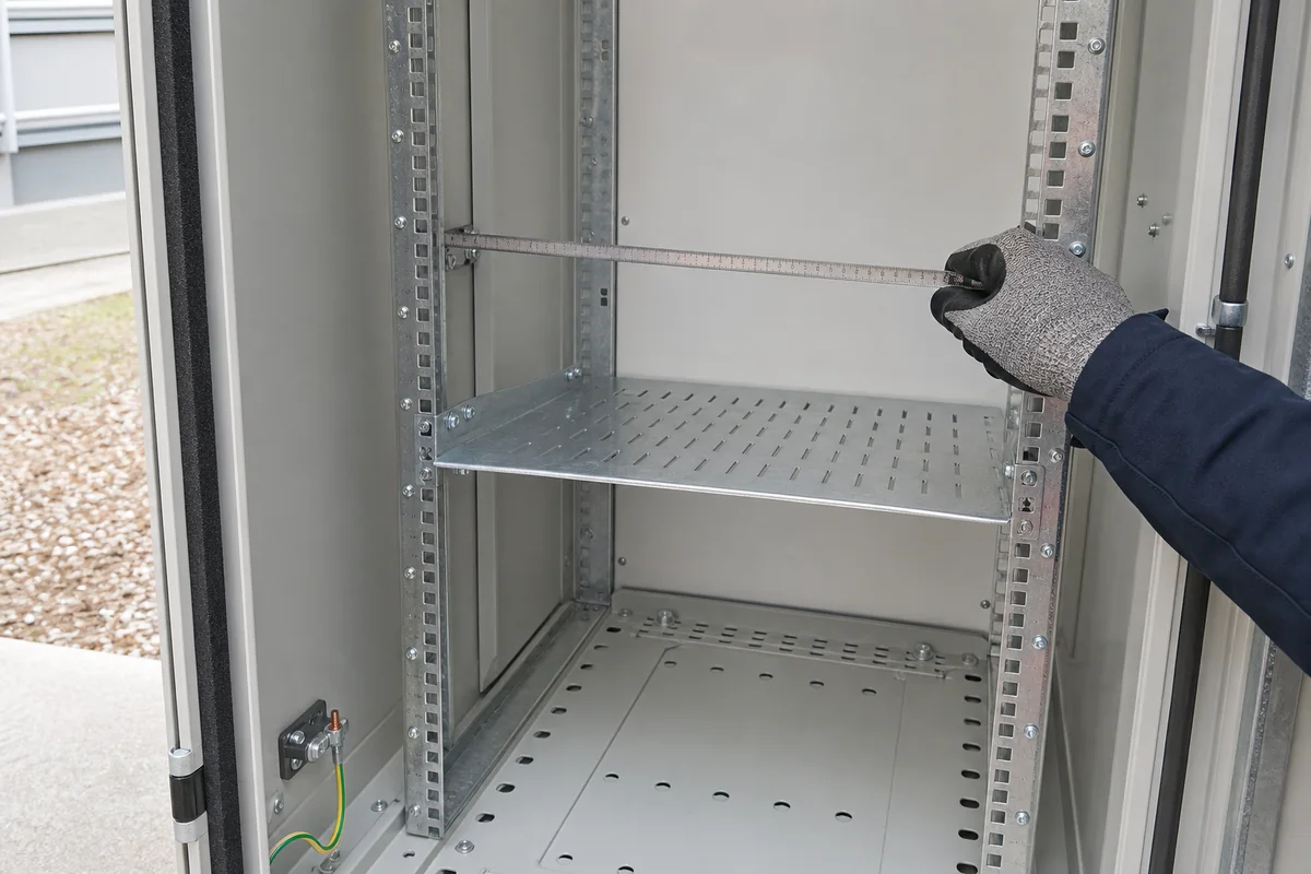
Rack Rail / Shelf Interface
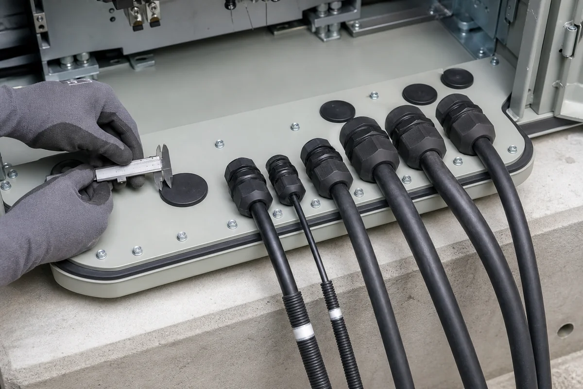
Cable Entry + Gland Plate
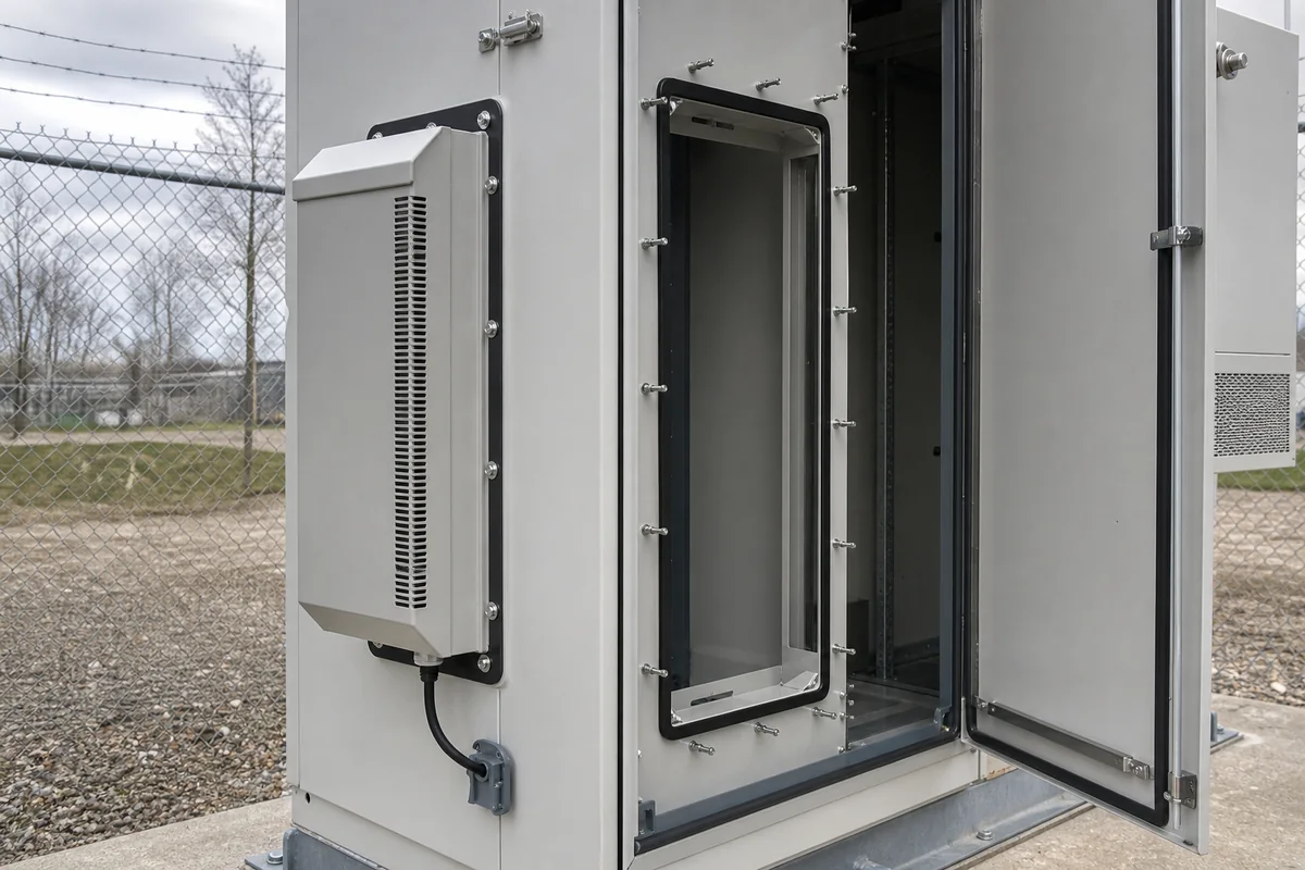
Cooling Hardware Opening
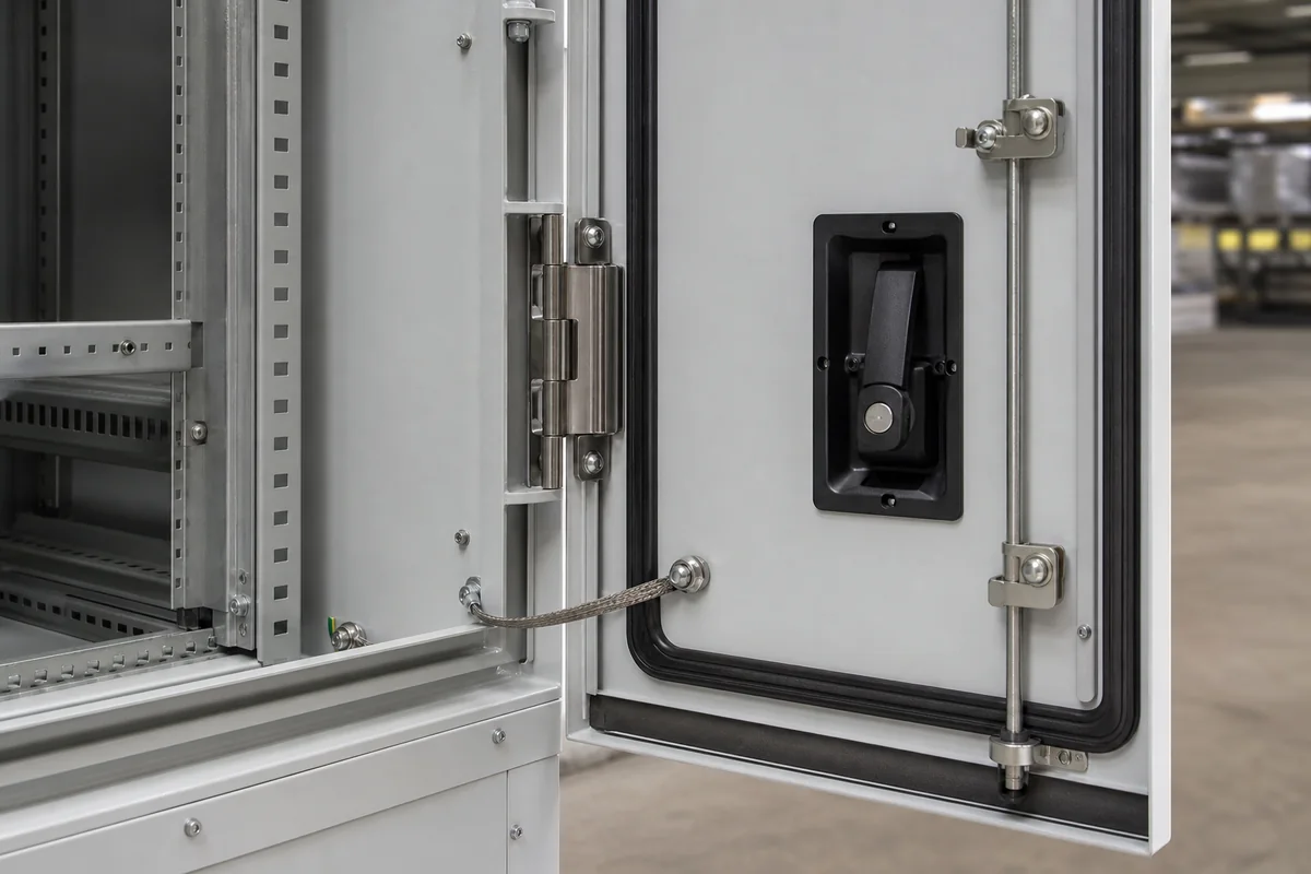
Door, Lock + Hinge Detail
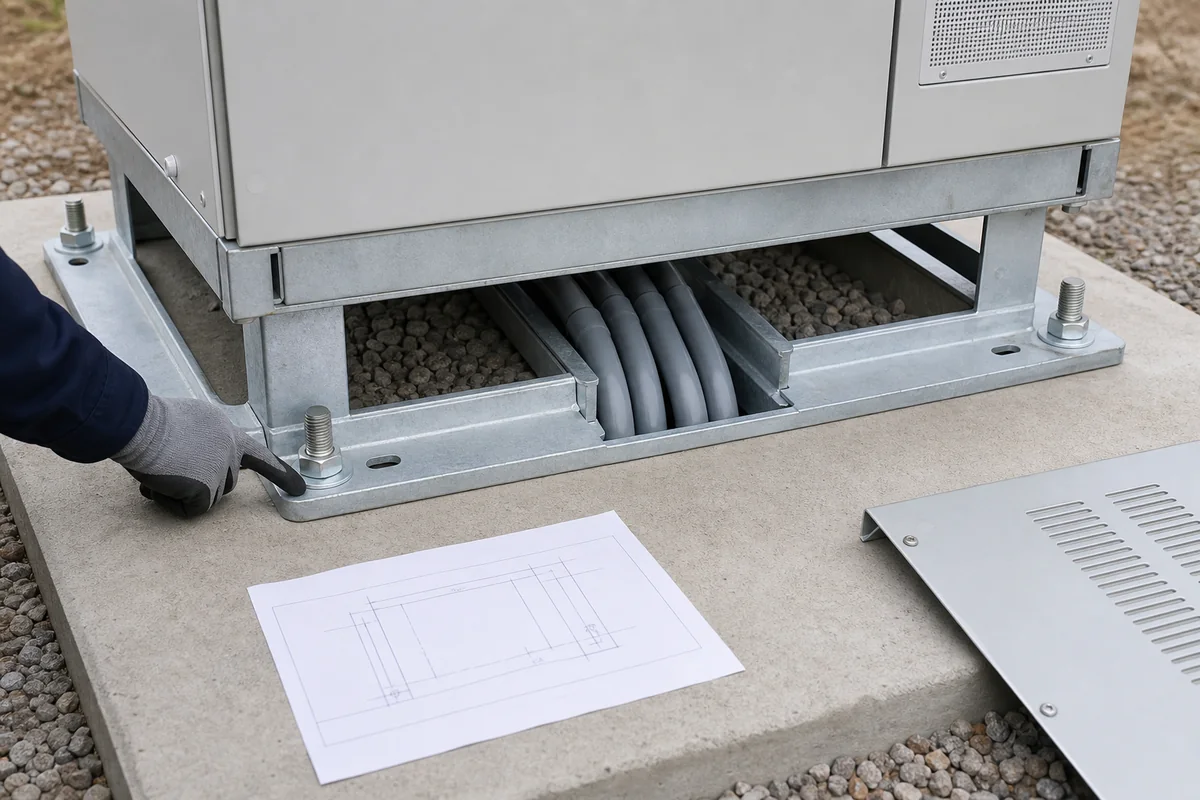
Pole / Pad / Plinth Mount
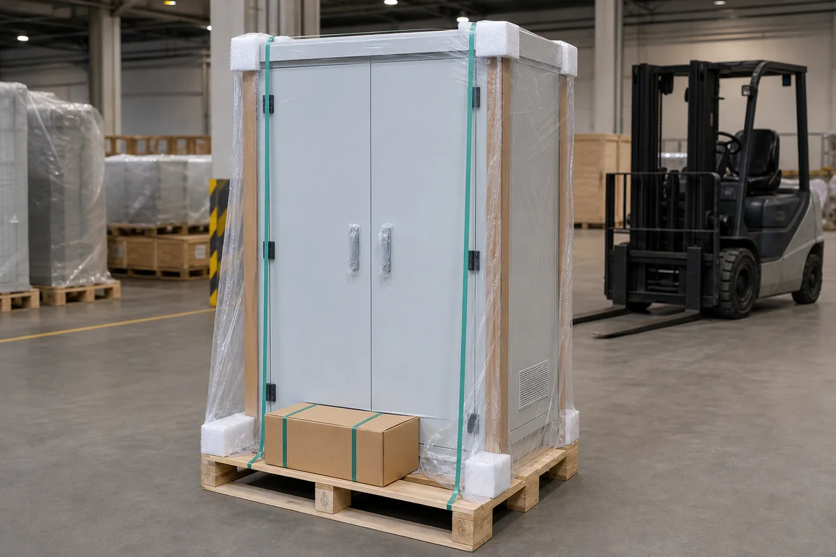
Packing for Site Deployment
08 / RESPONSIBILITY BOUNDARY
Telecom Cabinet-Body Scope vs. Complete Site-System Scope
A fabricated cabinet is the mechanical platform; it is not the network, battery, thermal or civil system.
FN Enclosure Manufacturing Scope
FN enclosure manufacturing scope:
- Cabinet body, doors, rack/mounting provisions, shelves, partitions and approved hardware.
- Approved openings, cable-entry plates, brackets and equipment mounting interfaces.
- Pole, wall, pad, plinth or foundation interfaces in the released drawing package.
- Material, finish and closure features within the agreed supply scope.
- Drawing-linked dimensional, visual, hardware and packing records as agreed.
Telecom OEM / Integrator / Site Contractor Scope
Telecom OEM / Integrator / Site Contractor Scope:
- Network architecture, radios, transmission equipment and performance.
- Power architecture, batteries, wiring, grounding and surge strategy.
- Cooling selection, condensation control and final thermal validation.
- Civil structure, site-load verification, installation and site sealing.
- Commissioning, monitoring and complete-site certification.
09 / PROJECT INFORMATION
Start with the rack, cable and site drawings
Use one site package so equipment, thermal, cable, power and installation interfaces stay coordinated.
Project Information Checklist
- Equipment list — models, dimensions, weight and replacement direction.
- Rack / backplate layout — rack units, rails, shelves, depth and reserved positions.
- Heat-load table — normal and peak losses by equipment zone.
- Site climate / orientation — ambient range, solar exposure, rainfall, dust and salt conditions.
- Cooling / moisture concept — hardware, service side, drainage and condensation responsibility.
- Fiber / cable schedule — counts, connector types, bend radius, slack and entry direction.
- Power / battery data — models, weights, partitions and ventilation/interface needs.
- Mounting drawing — pole, wall, pad, plinth or foundation and load responsibility.
- Maintenance / security — door swing, technician path, locks and public exposure.
- Commercial inputs — quantity, site variants, packing, target market and date.
Recommended First Package
- Equipment and rack elevation
- Heat-load and site conditions
- Fiber / cable entry plan
- Battery and mounting data
10 / FAQ
Outdoor Telecom Enclosure FAQ
Questions specific to rack, fiber, thermal, battery and outside-plant cabinet-body projects.
Does FN supply a complete outdoor telecom site?
This page covers the cabinet body and approved mechanical interfaces. Network equipment, power, batteries, wiring, cooling capacity, civil works, commissioning and complete-site certification remain with their responsible parties.
What is the minimum information needed to quote a telecom cabinet?
Start with the equipment list, rack or backplate layout, heat load, site climate and orientation, cable entries, battery data, mounting method, maintenance side, material and finish, quantity and date.
How should fiber routing be defined?
Provide fiber count, connector type, minimum bend radius, entry direction, slack-storage method and locations that must remain accessible after equipment installation.
Can FN provide cooling openings and mounting provisions?
FN can manufacture approved cutouts, brackets and service features from selected hardware drawings. The responsible system party selects and validates the complete thermal and condensation solution.
What information is needed for a battery compartment?
Provide battery type, model, dimensions, weight, cable direction, access and removal method, ventilation concept and any separation or structural requirements.
How should pole or foundation mounting be handled?
Provide an approved site-interface drawing, loads, orientation, anchor or bracket pattern, installation tolerances and the party responsible for structural verification.
Does an outdoor cabinet automatically guarantee final IP or NEMA performance?
No. Installed equipment, penetrations, field cable glands, assembly, mounting and site sealing affect the final verified configuration.
REVIEW THE EQUIPMENT AND SITE INTERFACES
Discuss the Rack, Fiber, Battery and Site Layout
Describe the cabinet in the contact form. Email rack and site drawings to info@fnenclosure.com with the project name and revision; we will identify missing mechanical inputs.