
Electrical Enclosures for Application Environments
Choose the application closest to your equipment, installation conditions and mechanical interfaces. Each route explains what changes the enclosure decision before quotation and drawing release.
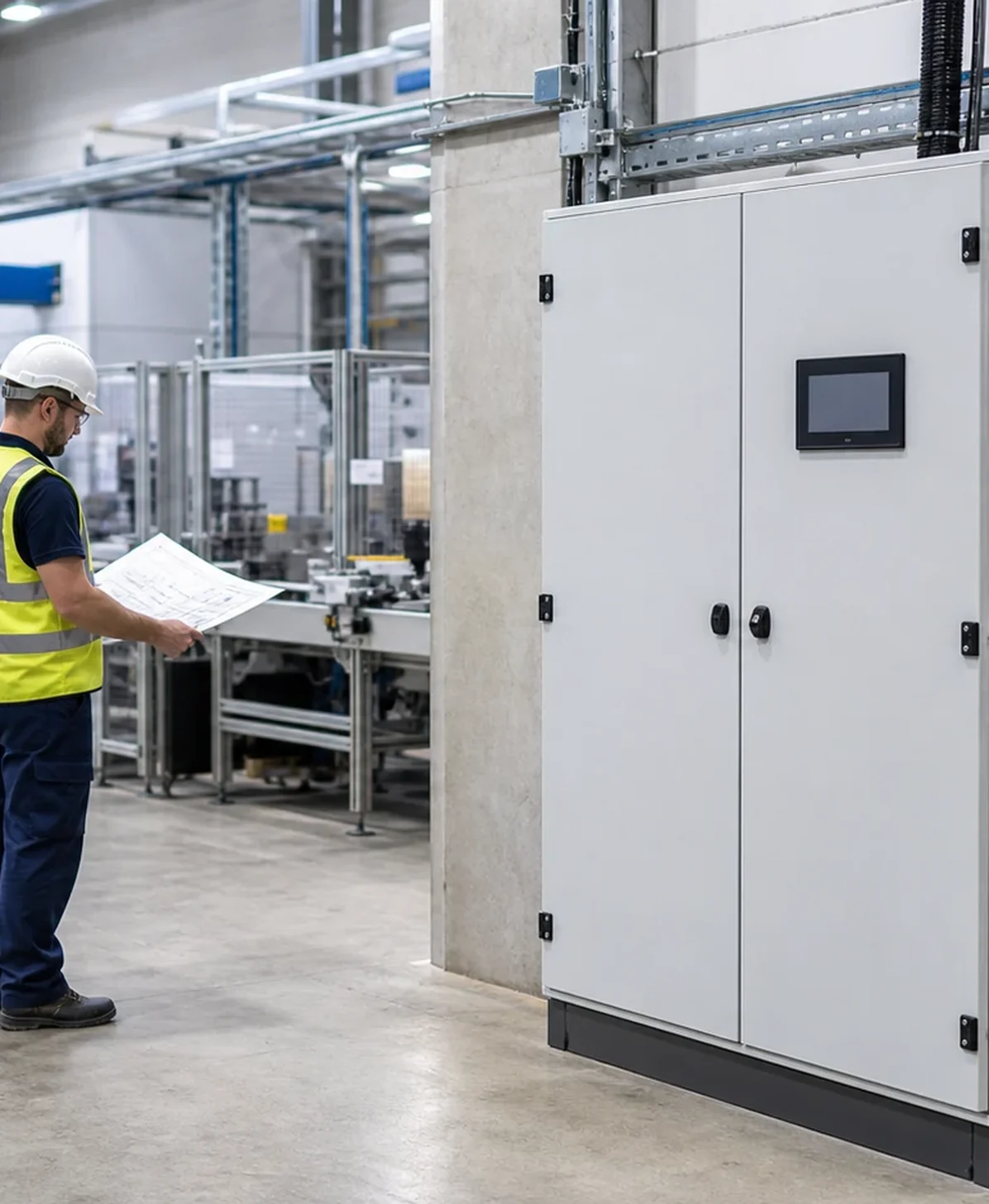
— 01 / Application Directory
Start With the Application Closest to Your Project
The application name is only the starting point. Open the detail page that best matches the equipment, environment and mechanical interfaces that must be controlled.
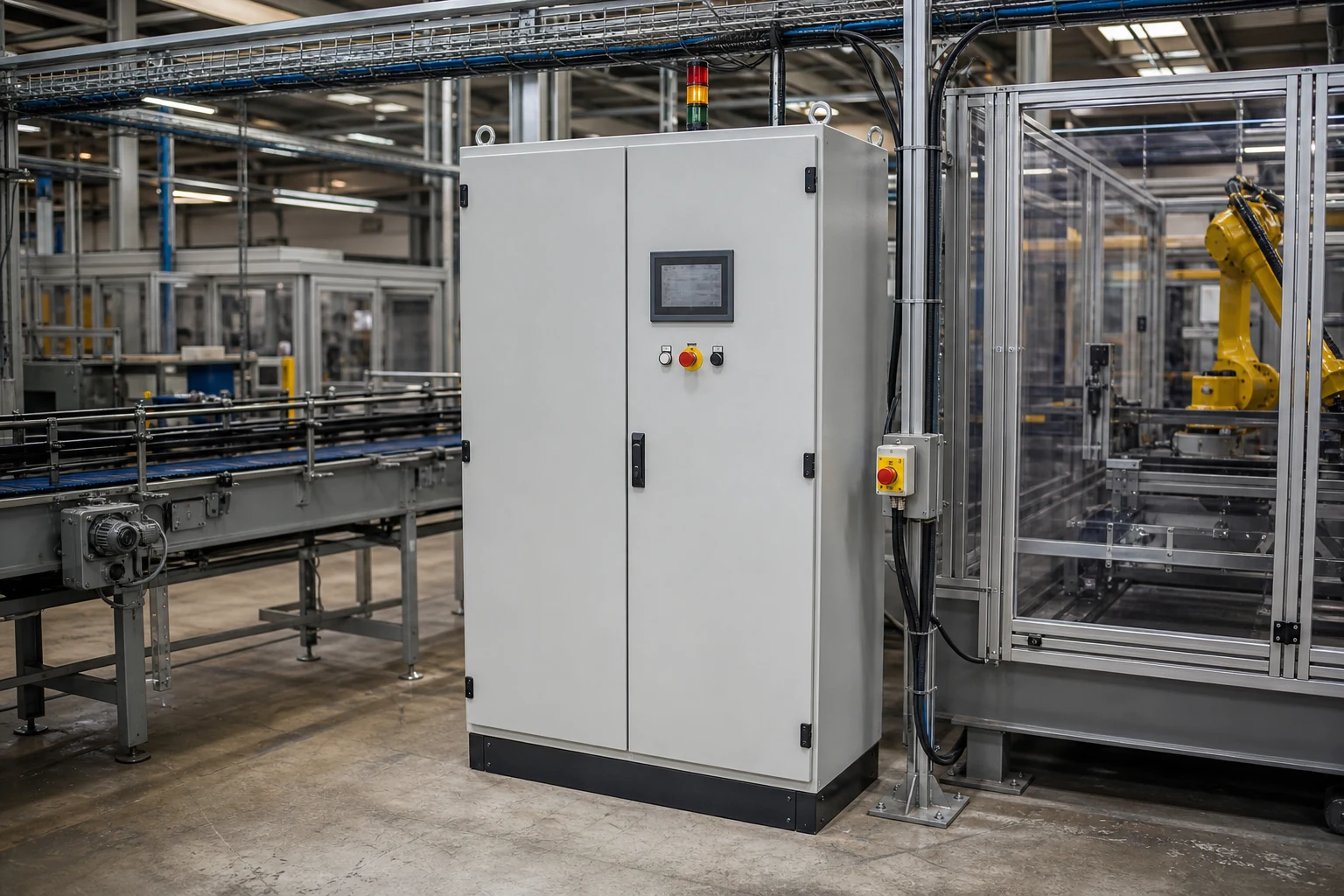
01 / 06 / CONTROLS & MACHINERY
Industrial Automation Enclosures
For PLC, I/O, HMI, VFD and servo-drive projects where layout, heat, door interfaces and cable separation affect the enclosure body.
- Backplate and component layout
- HMI, button and connector cutouts
- Drive heat and cable zones
- Machine mounting and service access
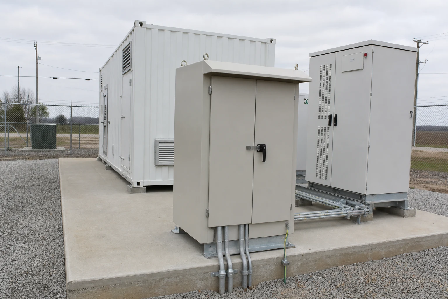
02 / 06 / BATTERY & POWER CONVERSION
Energy Storage Enclosures
For battery, PCS and auxiliary-system projects where equipment interfaces, load paths, cooling provisions and maintenance access must be frozen.
- Battery and PCS zones
- Cooling and fire-system interfaces
- Cable entry and lifting points
- Service and replacement access
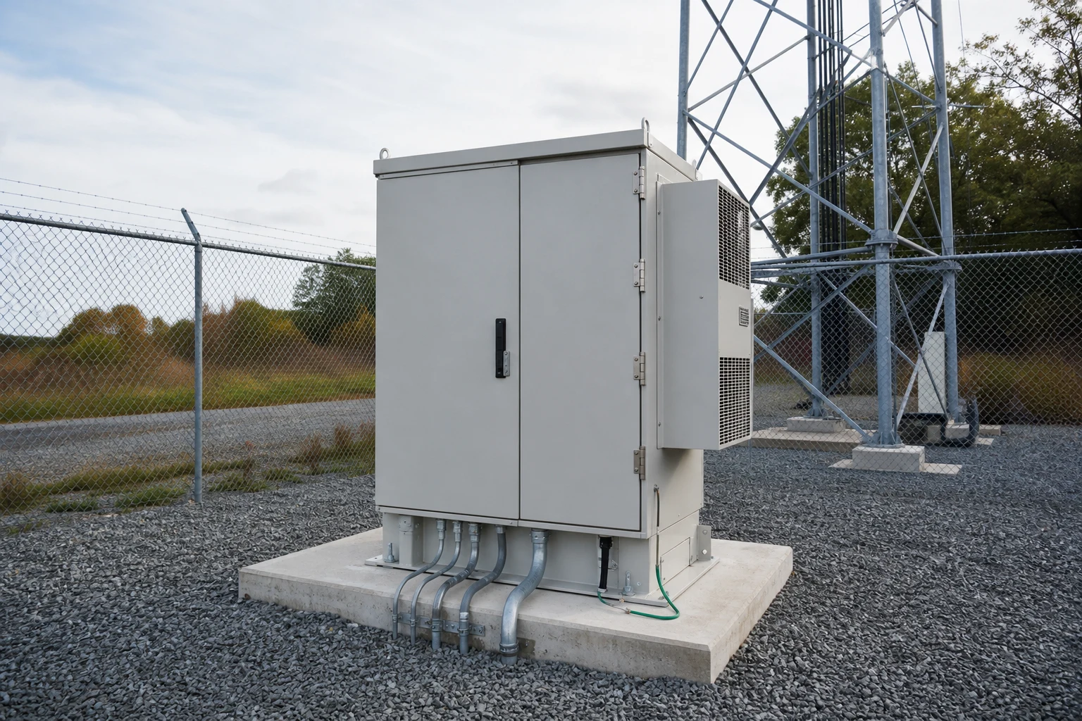
03 / 06 / NETWORK INFRASTRUCTURE
Telecom Enclosures
For outdoor network equipment where rack depth, fiber and copper entry, thermal hardware, batteries and site mounting interact.
- Equipment and rack clearance
- Fiber and copper routing
- Thermal and condensation inputs
- Pole, wall, pad or plinth mounting
04 / 06 / PV INFRASTRUCTURE
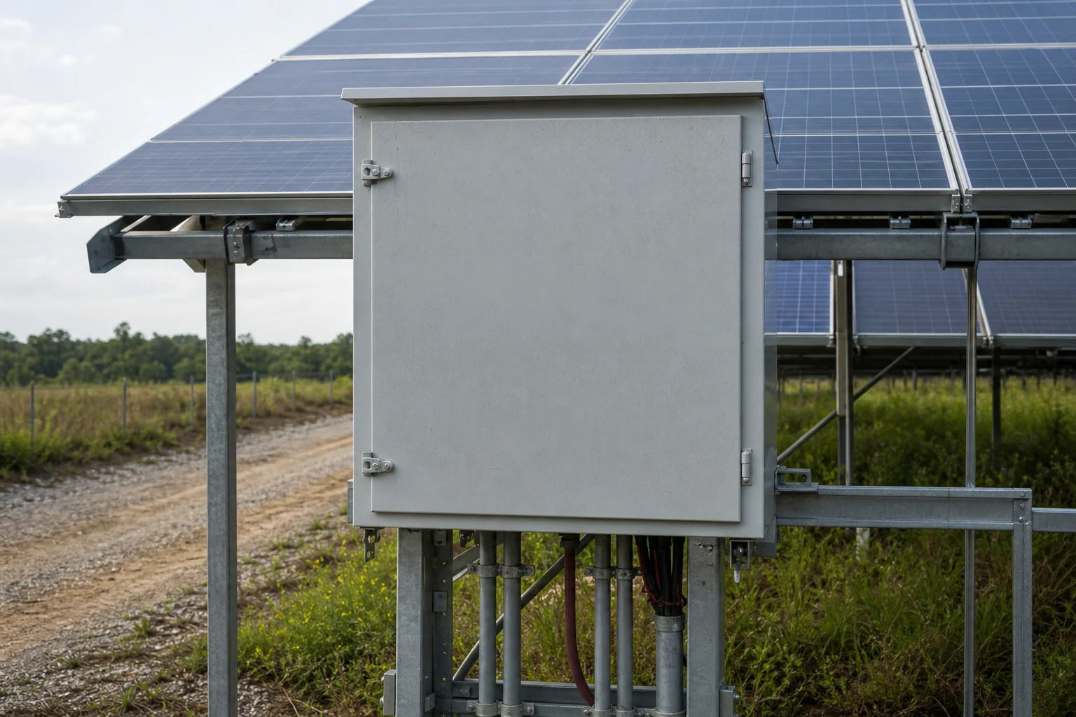
Solar Enclosures
For combiner, inverter-control and auxiliary equipment where site exposure, conductor entry, device layout and inspection access shape the body.
- PV equipment and device zones
- Solar and weather exposure
- DC, AC and communication entry
- Foundation or structure mounting
05 / 06 / DISTRIBUTION & CONTROL
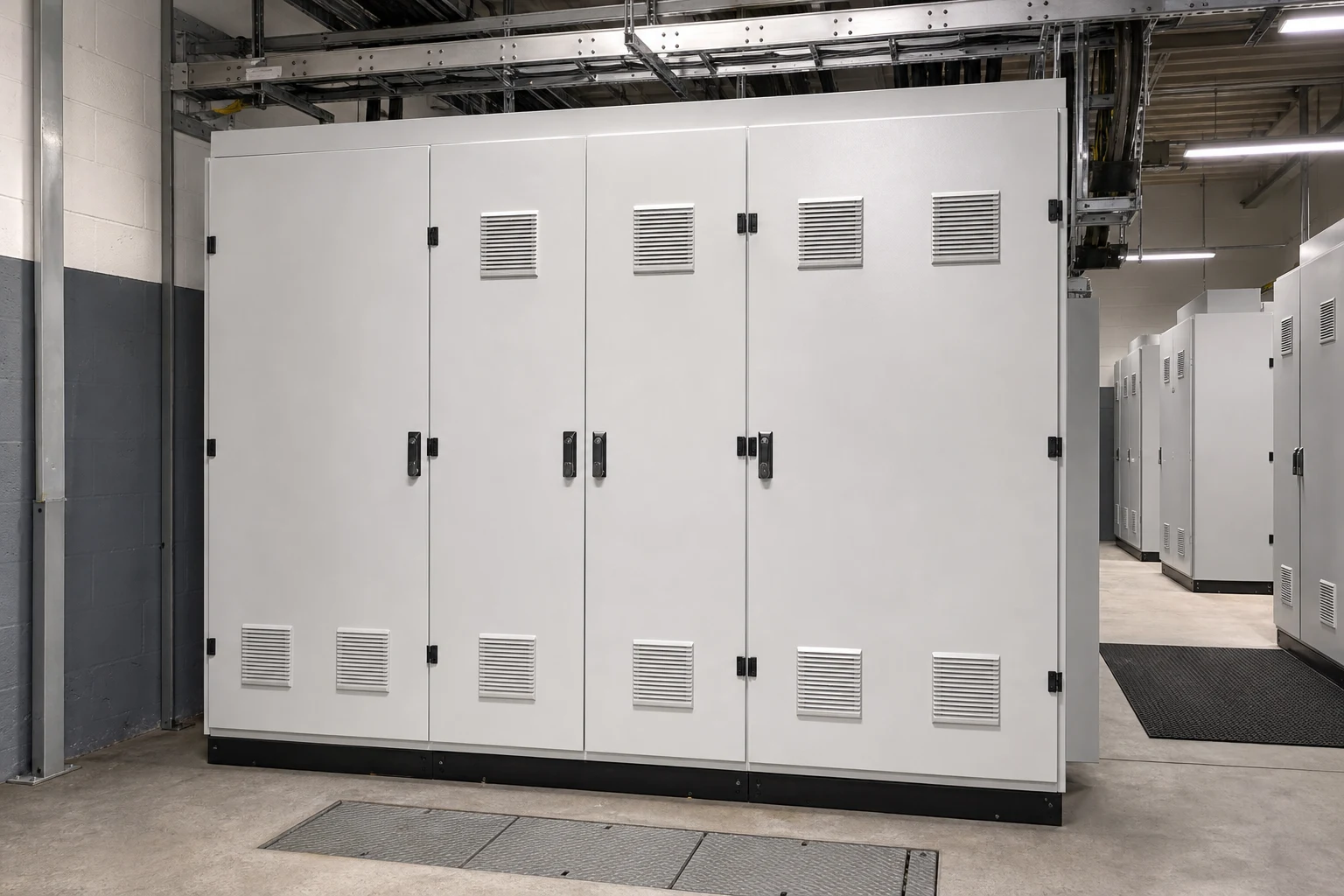
Power Distribution Enclosures
For breaker, busbar, terminal and feeder layouts where compartment geometry, cable bending space and access sequence change the mechanical platform.
- Incoming device and busbar zones
- Breaker and terminal access
- Cable bending and gland space
- Door, partition and interlock interfaces
06 / 06 / CHARGING EQUIPMENT
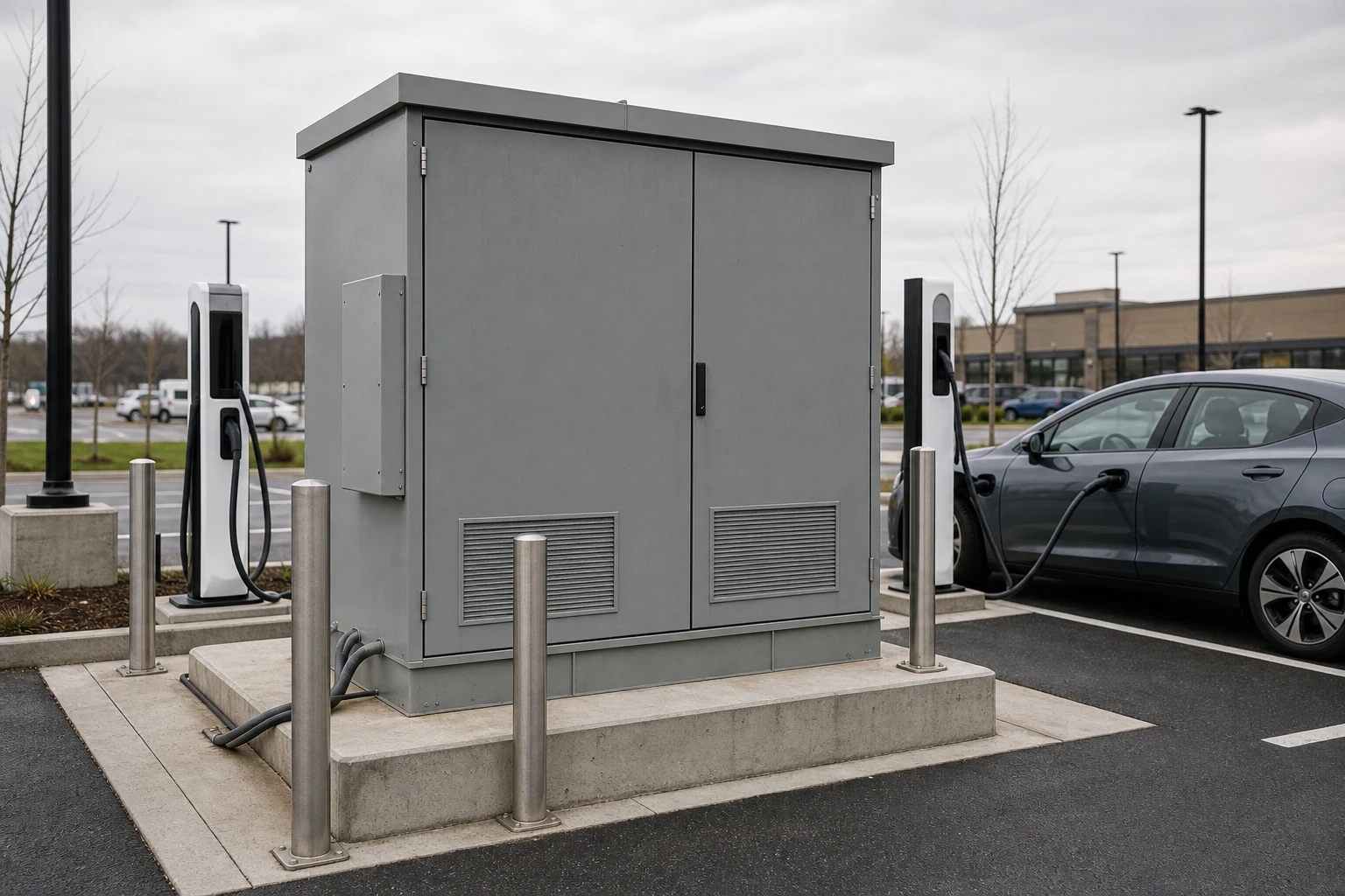
EV Charging Enclosures
For AC and DC charging equipment where public-site durability, cable handling, display interfaces, power modules and service access must align.
- Display, payment and control cutouts
- Charging cable and holster handling
- Cooling and module service paths
- Foundation and public exposure
— 02 / Project Constraints
Choose by the Constraint That Is Hardest to Change
When a project spans more than one application, start with the condition that will control the enclosure drawing and release sequence.
ENVIRONMENT
Site and exposure
Indoor or outdoor location, water, dust, corrosion, temperature, mounting surface and maintenance direction.
INTERFACES
Equipment and cutouts
Actual device models, mounting data, door openings, connectors, glands, display position and cable direction.
THERMAL
Heat and density
Declared device losses, clearances, airflow or cooling hardware, hot zones and the required service envelope.
PROJECT ROUTE
Scale and customization
Standard dimensions, controlled modifications, custom geometry, order quantity and drawing-release requirements.
03 / Enclosure Route
Use the Shortest Route That Still Controls the Interfaces
The application page should route the project without forcing every visitor into a fully custom enquiry.
Standard Enclosure
Use when a catalogue platform fits the outside envelope and internal arrangement.
• Envelope and depth already fit
• Standard door and mounting options
• Limited or no custom cutouts
• Fastest product-selection route
Modified Standard Enclosure
Use when the base body fits but defined openings, mounting plates or brackets change.
• Controlled cutout drawings
• Selected brackets or mounting changes
• Standard material and body geometry
• Approved revision before fabrication
Fully Custom Enclosure
Use when body dimensions, doors, compartments, mounting or repeated OEM requirements cannot be resolved on a standard platform.
• Project-specific body and door geometry
• Backplate and interface package
• Drawing-based quotation and release
• Quantity, QC and packaging inputs
04 / Detail Page Promise
Every Application Detail Page Should Answer These Questions
The Hub routes the visitor. The detail page must then make the mechanical and quotation questions visible before the visitor sends a request.
01 / APPLICATION FIT
Where does the enclosure fit?
Show the equipment, installation context, environmental constraints and the boundary between enclosure work and system integration.
02 / REAL INTERFACES
What must be mounted or opened?
Use actual models, dimensions, mounting patterns, cutouts, cable paths, door loads and service envelopes.
03 / ROUTE SELECTION
Which enclosure path fits?
Explain when a standard platform, controlled modification or custom body is the shortest safe route.
04 / REVIEW INPUTS
What changes the quotation?
Make the BOM, layout, thermal inputs, material, finish, quantity and revision status visible before enquiry.
05 / RELEASE LOGIC
What must be frozen?
Connect approved drawing revisions to cutouts, mounting, cable entry, access, inspection points and fabrication.
06 / RESPONSIBILITY
What is outside the enclosure scope?
Keep electrical design, system programming, commissioning and complete certification responsibilities explicit.
05 / RFQ-Ready Inputs
Send the Files That Make the Enclosure Decision Concrete
Start with what you have. Provisional information is useful when the revision status and open questions are clearly marked.
Project information checklist
• Target outside envelope and usable depth
• Equipment list, models and quantities
• Backplate, rail, bracket or mounting details
• HMI, button, connector and gland cutouts
• Cable entry direction and bending space
• Heat input, ambient conditions and cooling concept
• Material, finish and installation environment
• Quantity, drawing format and required date
Not sure which application fits?
Send the equipment type, installation location, known dimensions and a marked-up layout. FN can route the request to the most relevant application or custom path.
06 / Application FAQ
Questions Before You Choose a Route
Which application page should I start with?
Choose the route closest to the equipment or installation context. If the project combines several conditions, start with the application that has the hardest environment or interface constraint, then use the custom route for the combined brief.
Do the application pages replace the product pages?
No. The Hub helps select a starting point. Product pages describe enclosure families, while application pages explain how equipment, environment and fabrication inputs affect the choice.
Can FN make a custom enclosure for my application?
Use the Custom Electrical Enclosures route when the standard platform cannot resolve the required envelope, door geometry, mounting, cutouts, material, finish or quantity.
Can FN design and program the complete electrical system?
This page is an enclosure and mechanical-interface route. Electrical system design, wiring, programming, commissioning and complete system certification remain with the responsible integrator or equipment manufacturer unless separately defined in writing.
What if I only have photos and a rough layout?
Send the photos, marked-up layout, known dimensions and open questions. Label provisional information clearly so quotation and drawing-review assumptions can be controlled.
Start with the project context
Choose an Application, Then Send the Real Inputs
Use the route that best matches your project—or send the equipment, environment and drawing information directly to FN.