
Energy Storage Enclosures for Battery, PCS and Auxiliary Equipment
FN makes enclosure bodies for battery equipment, PCS and site auxiliaries. Share the equipment layout, weights, service paths, cable entry, lifting method, base drawing, and cooling and fire-hardware interfaces for mechanical review before fabrication.
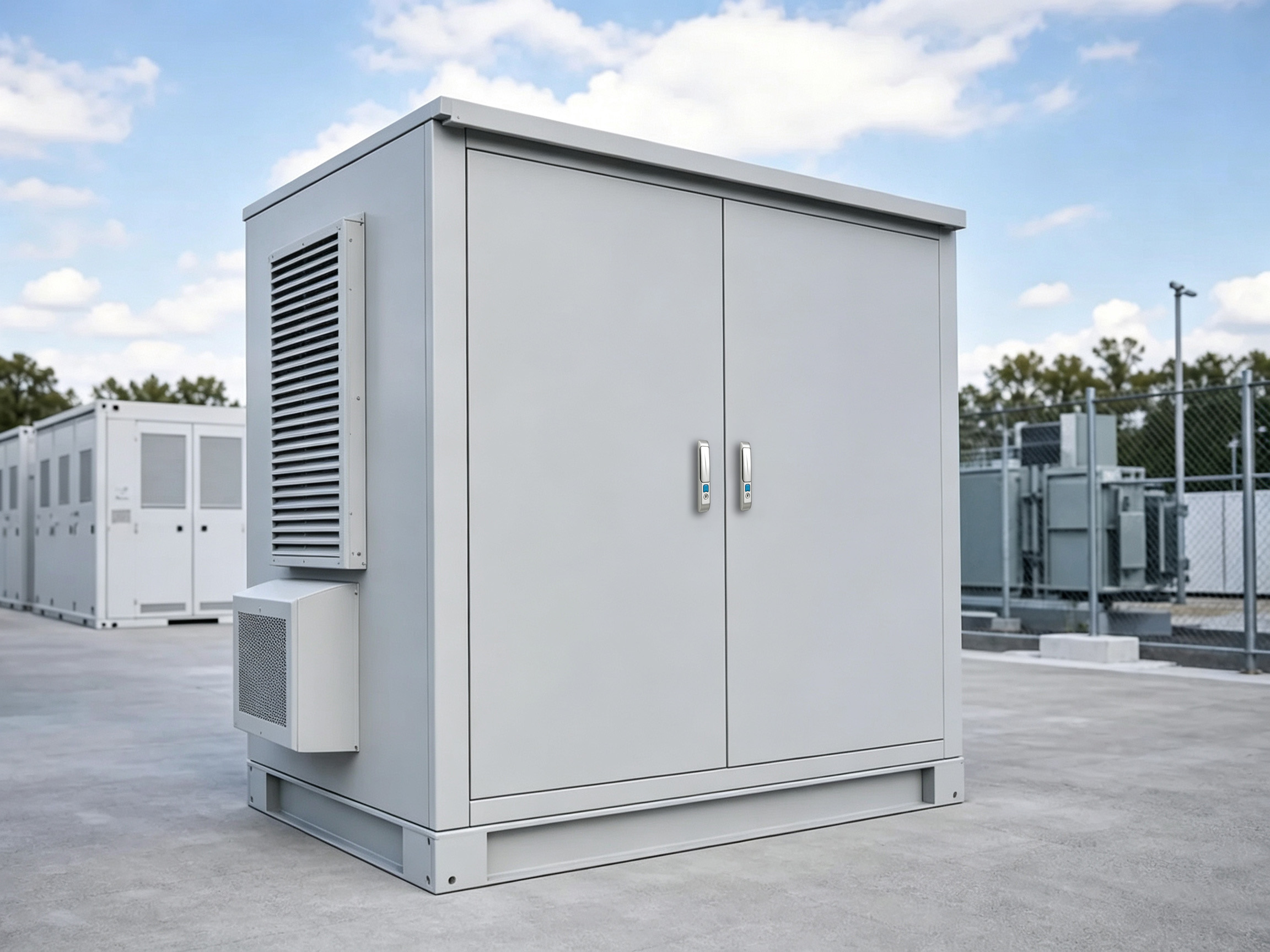
01 / SYSTEM POSITION
How the cabinet body fits the BESS layout
Battery, PCS and auxiliary equipment set the loads and access needs. The cabinet body provides the agreed compartments, cable paths, base and mechanical provisions for selected cooling and fire hardware.
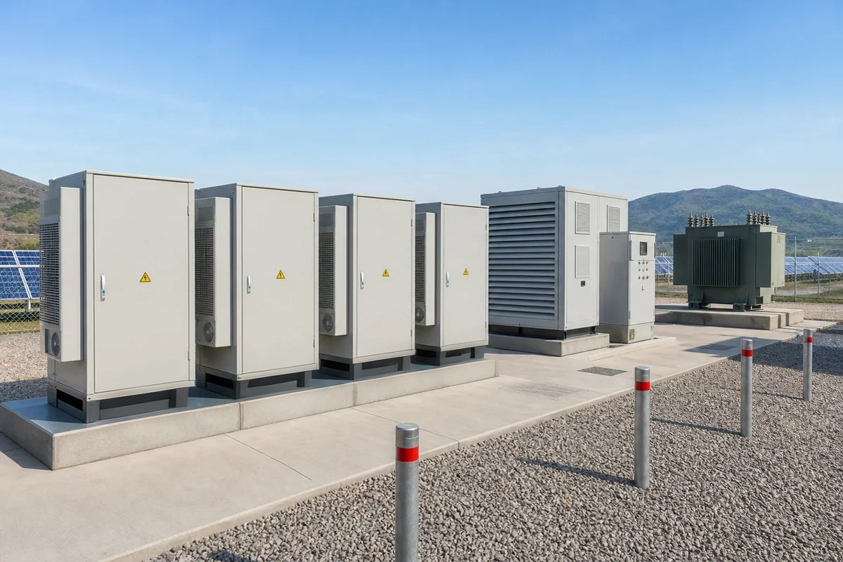
BESS Mechanical Interface Map
INTERNAL EQUIPMENT ZONES
PCS / Power Conversion
Equipment envelope, weight, mounting, heat and service direction.
Battery / DC Zone
Rack or module envelope, support loads, isolation and removal path.
Controls + Auxiliary Power
Backplate space, cable segregation, access and low-voltage interfaces.
Partitions + Maintenance Aisle
Compartment walls, door sequence and equipment replacement envelope.
EXTERNAL INTERFACES
Cooling + Fire Provisions
Approved openings, brackets and service sides only.
Cable + Base + Lifting
Entry zones, foundation holes, center of gravity and lifting points.
Mechanical scope map · cooling, fire protection and electrical functions remain with their responsible system parties
FN manufacturing scope
- Cabinet body, doors, partitions, mounting plates, base/plinth and defined structure.
- Approved mechanical provisions for equipment, cooling, fire hardware and cable entry.
- Lifting or transport features only when defined in the approved package.
- Agreed drawing-linked dimensional and visual inspection records.
Boundary: FN does not design the battery system, PCS, wiring, controls, cooling capacity, fire strategy, commissioning or complete BESS certification unless separately documented and verified.
02 / TYPICAL CONFIGURATIONS
Choose a body for battery, PCS or site auxiliary equipment
A cabinet for battery equipment, PCS equipment or station auxiliaries does not share the same weight, heat, service and interface priorities.
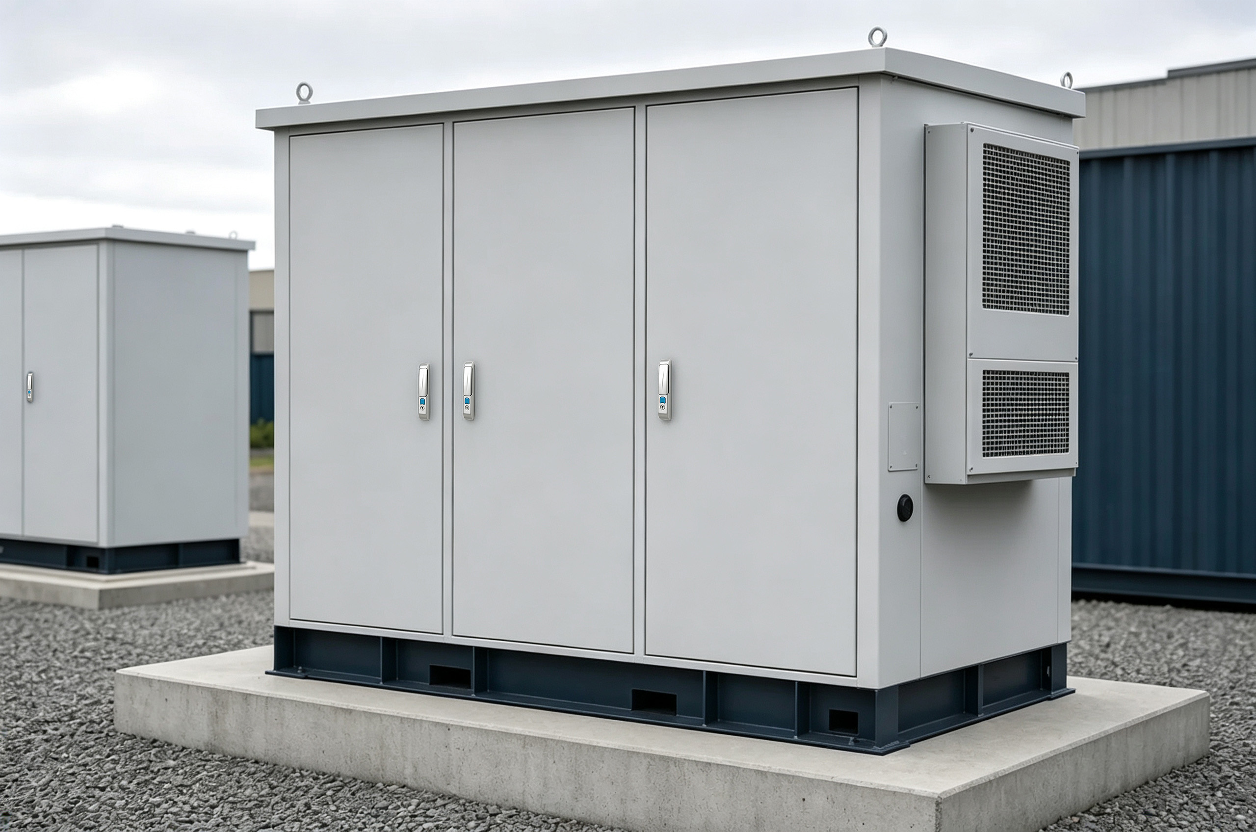
Outdoor BESS Equipment Cabinet
Custom or repeat-platform bodies for battery and auxiliary equipment installed at outdoor energy sites.
- Equipment and compartment layout
- Solar and ambient conditions
- Base, lifting and transport inputs
- Door and module removal paths
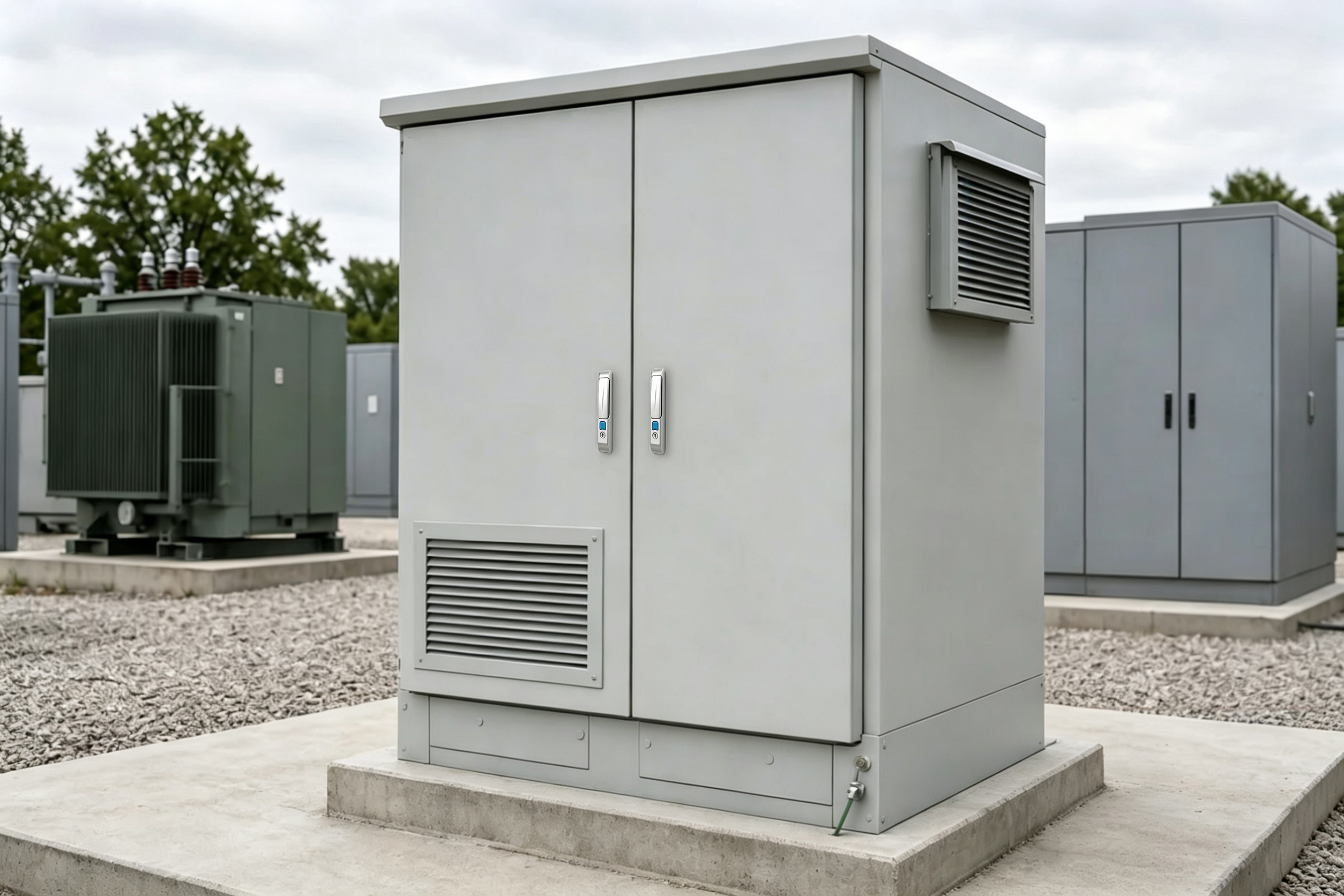
PCS / Power Conversion Cabinet
Enclosure bodies around power electronics where weight, heat and power-cable routing drive the mechanical package.
- PCS dimensions and losses
- Cooling interface drawing
- Heavy-device support
- Power cable bend space
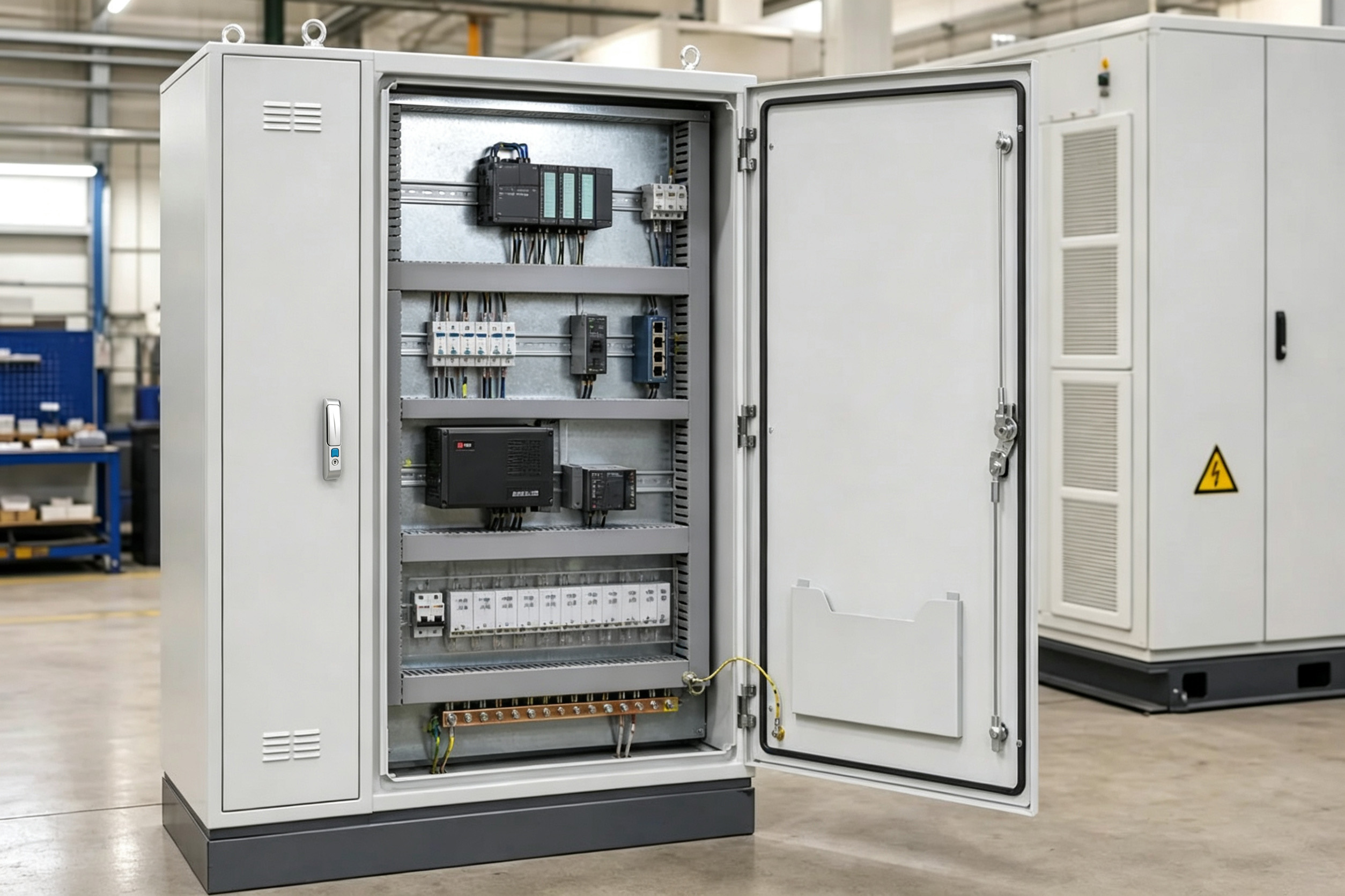
Station Auxiliary / Control Cabinet
Control, communication, auxiliary power or monitoring enclosure bodies linked to the wider BESS site.
- Backplate and HMI layout
- Low-voltage cable zones
- Site mounting interface
- Maintenance and replacement access
03 / FAILURE MODES
BESS Interface Changes That Cause Expensive Enclosure Rework
Confirm the loads, compartments and external openings before fabrication. Outside dimensions alone do not define the cabinet.
Equipment layout changes after body release
Consequence: Cutouts, partitions, supports or doors require rework.
Mechanical decision: Usable volume, mounting structure and compartment geometry.
Required input: Released equipment list and coordinated layout.
Weight, center of gravity or lifting method is missing
Consequence: Unsafe handling assumptions or a redesigned base.
Mechanical decision: Base structure, lifting points and transport restraints.
Required input: Equipment weights, center-of-gravity estimate and lifting plan.
Cooling interface is selected late
Consequence: Large opening changes, sealing conflicts or blocked service.
Mechanical decision: Cutout, support, door zone and airflow-path provisions.
Required input: Cooling hardware drawing, heat input and service side.
Fire-system provisions are assumed
Consequence: Late penetrations or conflicts with equipment zones.
Mechanical decision: Openings, brackets, reserved space and access.
Required input: Approved fire-system interface drawing and responsibility note.
Power and control cable entries overlap
Consequence: Bend radius, termination and segregation become difficult.
Mechanical decision: Gland plates, bottom zones, barriers and base openings.
Required input: Cable schedule, entry direction and minimum bend space.
Module replacement path is not reviewed
Consequence: Equipment cannot be removed without dismantling adjacent parts.
Mechanical decision: Door size, removable panels, aisle and obstruction control.
Required input: Maintenance sequence and replacement envelope.
04 / DESIGN REVIEW MATRIX
Seven interfaces to approve before fabrication
The enclosure drawing should show where each external system ends and which mechanical provision FN is expected to manufacture.
Equipment Layout
Interface: Overall envelope, mounting coordinates, weight and service direction.
Review question: Are PCS, battery and auxiliary equipment models frozen?
Release evidence: Equipment list + coordinated general arrangement.
Compartments
Interface: Partitions, access sequence, isolation zones and removable panels.
Review question: Which functions require physical separation?
Release evidence: Compartment plan + door/service sequence.
Cooling Provisions
Interface: Openings, brackets, loads, condensate route and service side.
Review question: Who selects and validates thermal performance?
Release evidence: Cooling hardware drawing + loss/ambient data.
Fire-System Provisions
Interface: Reserved space, penetrations, brackets and access.
Review question: Which party owns detection, suppression and final compliance?
Release evidence: Approved interface drawing + responsibility matrix.
Cable Entry
Interface: Power, control, communication and grounding entry zones.
Review question: What enters from the base, side or top?
Release evidence: Cable schedule + gland/base opening plan.
Base + Foundation
Interface: Anchor pattern, plinth, fork pockets, leveling and site interface.
Review question: Is the final foundation drawing available?
Release evidence: Base drawing + anchor loads/positions.
Lifting + Transport
Interface: Gross weight, center of gravity, lifting points and packing restraints.
Review question: How will the populated cabinet be handled?
Release evidence: Weight table + lifting/transport method.
05 / CONFIGURATION ROUTES
Choose a Platform Based on Interface Stability—not Only Cabinet Size
The shortest safe route depends on whether the equipment zones and external interfaces already fit a proven platform.
Modified Outdoor Platform
Use when a standard outdoor cabinet envelope fits and only controlled openings, mounting plates or base features change.
- Known body platform
- Project-specific interface drawings
- Best when equipment envelope is stable
Custom BESS Cabinet Body
Use when equipment density, partitions, weight, doors, cooling openings or site mounting require a project-specific body.
- Coordinated interface package
- Structure and service review
- Approved CTQs before first article
Repeat OEM Enclosure Platform
Use when one released architecture will be produced across project batches with controlled variants.
- Master drawing and option matrix
- Revision-controlled interfaces
- First-article and batch evidence plan
06 / BEFORE QUOTATION
What to confirm for a BESS enclosure quote
Mark each input as approved or provisional, and keep out-of-scope system work separate from the enclosure quotation.
Start with the available layout; approve interfaces before fabrication
FN reviews the submitted system layout to define enclosure geometry, compartments, structural assumptions, external provisions, requested records and commercial conditions.
Equipment & Weight
Models, envelopes, mounting, individual weights, gross weight and center-of-gravity assumptions.
Compartments & Service
Partitions, door sequence, maintenance side and module removal path.
Cooling & Fire Provisions
Approved hardware interfaces, cutouts, supports, access and responsibility.
Cable & Grounding Interfaces
Power/control/communication entry zones, bend space and grounding provisions.
Base, Site & Transport
Foundation, anchors, plinth, lifting, forklift and shipping restraints.
Commercial & Quality Inputs
Quantity, variants, target market, customer specification, CTQs, packing and date.
Gate 01 · Equipment Freeze
Confirm equipment list, envelopes, weights and mounting data.
Gate 02 · Zone Freeze
Approve compartments, access sides and replacement paths.
Gate 03 · External Interface Freeze
Approve cooling, fire, cable, base and lifting provisions.
Gate 04 · Structure Review
Align loads, doors, partitions, supports and transport assumptions.
Gate 05 · Drawing Approval
Freeze revision, tolerances, CTQs and responsibility notes.
Gate 06 · First-Article Plan
Define dimensions, photos and records required for approval.
Gate 07 · Batch Release
Control variants and produce against the approved master package.
Mechanical Details to Review
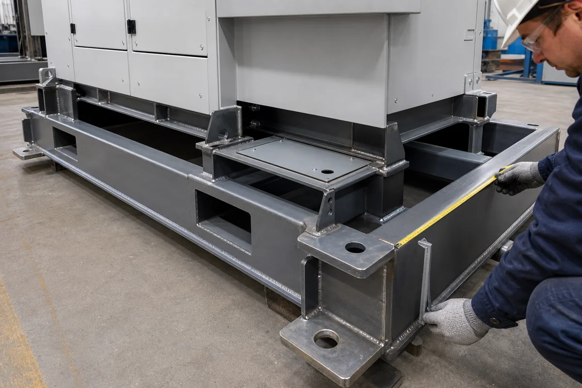
Base / Plinth Weldment
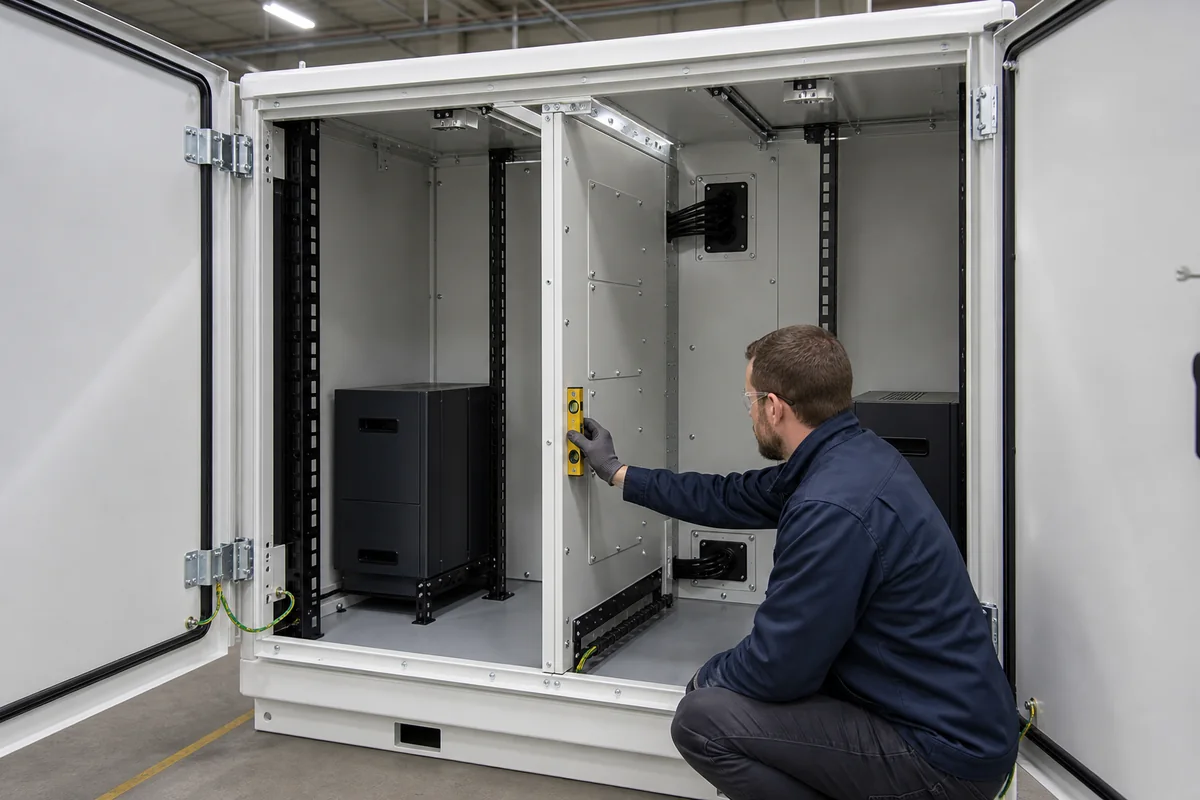
Compartment + Partition Detail
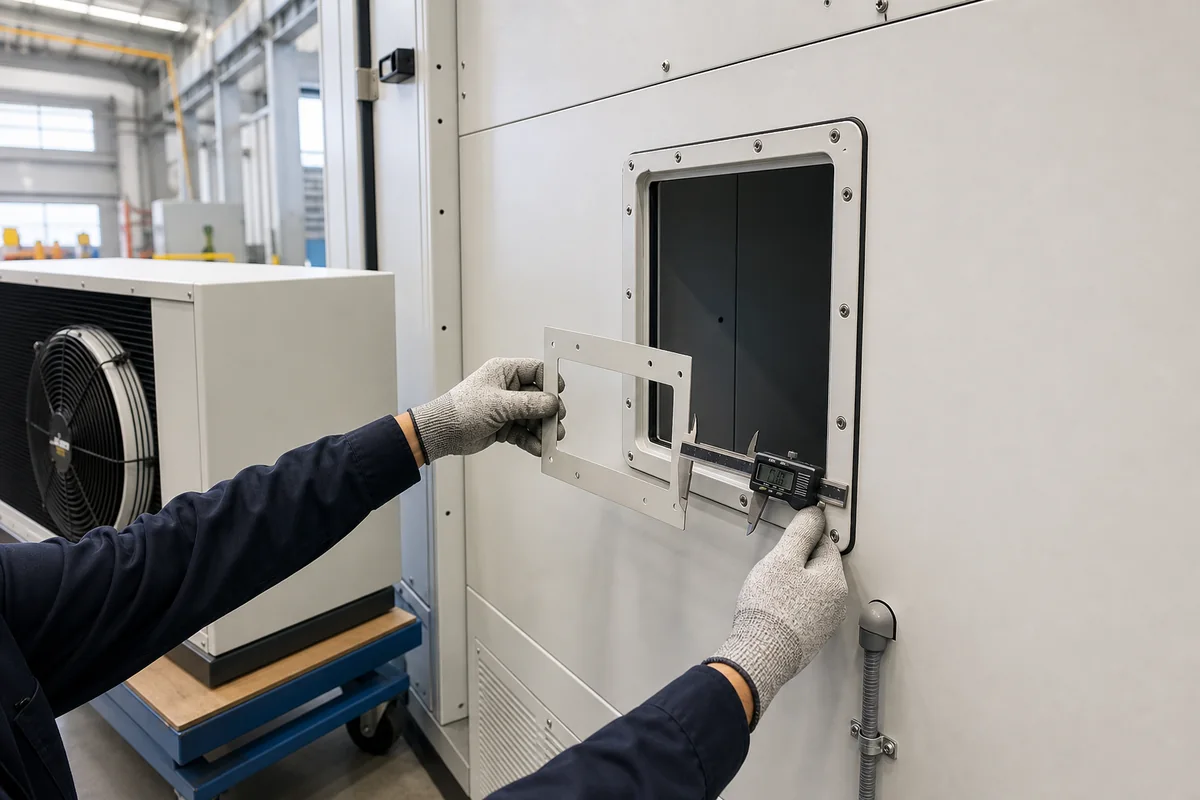
Large Cutout / Interface Check
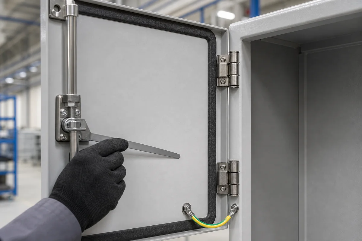
Door, Hinge + Gasket Path
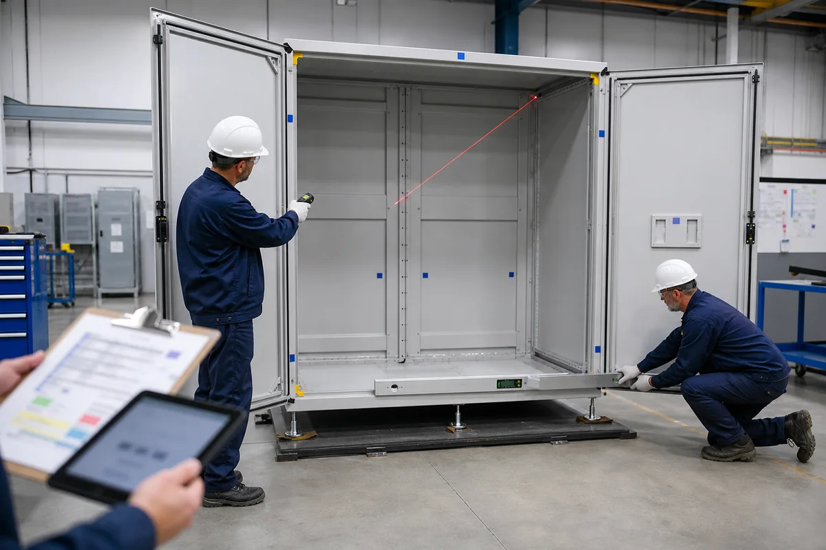
First-Article Checks to Specify
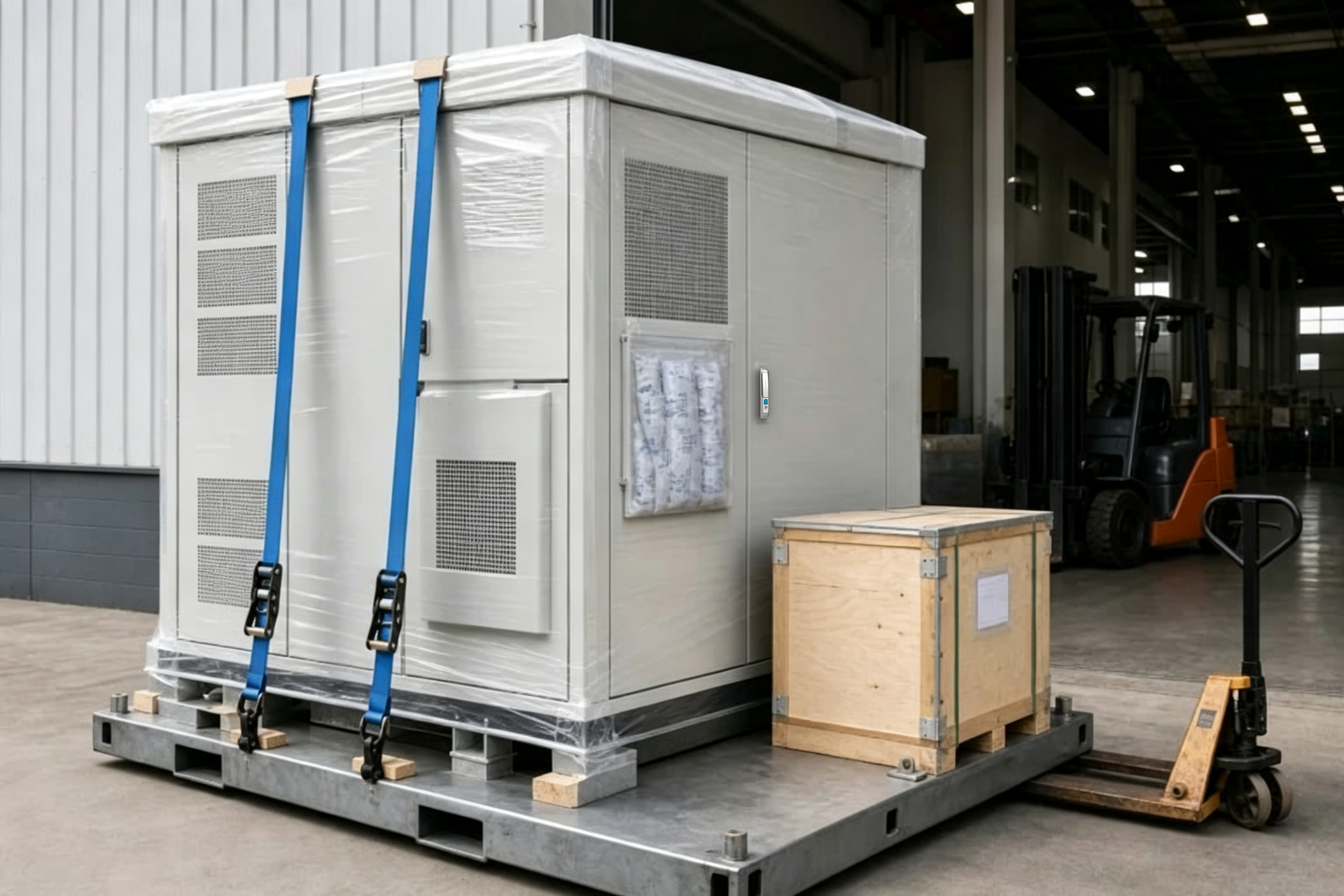
Transport Protection + Packing
08 / RESPONSIBILITY BOUNDARY
Enclosure-Body Responsibility vs. Complete BESS Responsibility
Separate the fabricated mechanical platform from the electrical, thermal, fire-protection and site system that others select and validate.
FN Enclosure Manufacturing Scope
FN enclosure manufacturing scope:
- Body, doors, partitions, mounting structures, base/plinth and approved hardware.
- Approved cutouts, penetrations, brackets and cable-entry provisions.
- Defined lifting or transport features in the released drawing package.
- Material, finish and enclosure assembly within the agreed supply scope.
- Drawing-linked dimensional, visual or packing records as agreed.
BESS OEM / Integrator / EPC Scope
BESS OEM / Integrator / EPC Scope:
- Battery, PCS, auxiliary equipment and electrical architecture.
- Wiring, grounding, controls, communication and functional safety.
- Cooling selection, condensation control and final thermal validation.
- Fire detection, suppression strategy and complete fire compliance.
- Site foundation, installation, commissioning and final system certification.
09 / PROJECT INFORMATION
Send the BESS enclosure layout and interface package
For an initial review, include the general arrangement and equipment weights. Mark any cable, cooling, fire-hardware or base drawing that is still provisional.
Project Information Checklist
- System general arrangement — equipment zones, service sides and overall envelope.
- Equipment schedule — models, dimensions, mounting and individual weights.
- Compartment plan — partitions, doors, isolation needs and replacement paths.
- Cooling interface — hardware drawings, losses, ambient and service direction.
- Fire-system interface — approved provisions and responsibility boundary.
- Cable entry plan — power, control and communication routes with bend space.
- Base / foundation drawing — anchors, plinth, leveling and site interface.
- Lifting / transport data — gross weight, center of gravity and handling method.
- Environment / finish — indoor or outdoor conditions, corrosion and coating direction.
- Commercial / quality inputs — quantity, variants, CTQs, packing and required date.
Recommended First Package
- System general arrangement
- Equipment list with weights
- Cooling / fire interface drawings
- Cable-entry and base drawings
10 / FAQ
Energy Storage Enclosure FAQ
Questions specific to BESS, PCS and station auxiliary enclosure-body projects.
Does FN supply a complete battery energy storage system?
This page covers enclosure bodies and approved mechanical interfaces. Battery, PCS, electrical, cooling, fire-protection, controls, commissioning and complete-system certification remain with their responsible parties unless separately contracted and verified.
What should be frozen before the enclosure drawing is released?
Freeze the equipment list, zones, weights, compartments, service paths, cooling and fire provisions, cable entry, base, lifting method and the drawing revision used for manufacture.
Can FN manufacture multi-compartment BESS cabinets?
FN can review compartment walls, doors, supports and access features when they are defined in an approved mechanical package. Required electrical or fire separation performance must be specified and verified by the responsible system party.
How should cooling and condensate interfaces be handled?
Provide selected hardware drawings, heat inputs, ambient conditions, service side and condensate concept. FN can manufacture approved provisions; the system designer validates thermal and moisture performance.
What lifting information is needed?
Provide populated weight estimates, center-of-gravity assumptions, handling method, lifting orientation, site restrictions and any required test or inspection criteria.
How are project variants controlled across batches?
Use a released master drawing, option matrix, variant-specific BOM and revision-controlled CTQs so openings, bases, doors and accessories are not mixed.
Does the empty cabinet guarantee final IP or NEMA performance?
No. Installed equipment, penetrations, gaskets, assembly, field changes and the complete verified configuration affect final performance.
START WITH THE EQUIPMENT LAYOUT
Discuss the Layout, Weight Table and Base Drawing
Use the contact form for a project summary. Email drawings to info@fnenclosure.com with the project name and revision. We will review missing mechanical inputs before drawing approval.