
Outdoor Solar Enclosures for Combiner, Control and Site Equipment
FN makes enclosure bodies for combiner, inverter-control and site auxiliary equipment. Review the equipment envelope, site exposure, cable entry and water path, mounting method and service direction before the fabrication drawing is approved.
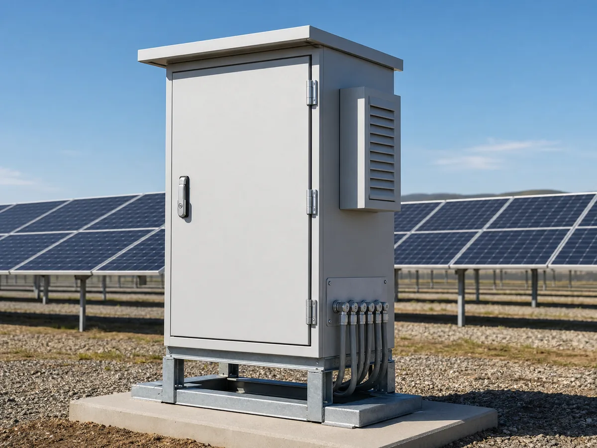
01 / SYSTEM POSITION
Which solar equipment will the enclosure house?
The body may house combiner hardware, inverter controls, communications or site auxiliaries. Each route needs its own equipment and cable layout; the electrical design remains with the responsible system party.
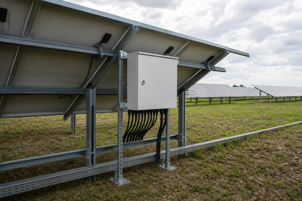
Outdoor Solar Mechanical Interface Map
EQUIPMENT + INTERNAL ZONES
Combiner / Junction Equipment
Backplate area, terminals, protection-device envelope and cable bend space.
Inverter / Control Interfaces
Equipment weight, heat, openings, service direction and mounting.
DC / AC / Communication Zones
Entry separation, gland plates, barriers and accessible termination space.
OUTDOOR + SITE INTERFACES
Solar + Weather Exposure
Orientation, ambient, direct sun, rain path and corrosion conditions.
Entry + Drainage + Mounting
Bottom/side cable entry, field-drilling control, wall/pole/skid/pad interface.
Mechanical scope map · not a photovoltaic electrical design or complete combiner-box specification
FN manufacturing scope
- Enclosure body, door, mounting plate, gland plates, brackets and defined structure.
- Approved cutouts and mechanical provisions for selected equipment or accessories.
- Wall, pole, skid, plinth or pad interfaces in the released drawing.
- Agreed material, finish, dimensional and packing records.
Boundary: FN does not design the PV electrical architecture, protection coordination, wiring, grounding, inverter function, thermal validation, site installation or complete-system certification unless separately documented and verified.
02 / TYPICAL CONFIGURATIONS
Three Solar Enclosure Routes With Different Interface Priorities
A combiner body, inverter-control cabinet and site auxiliary enclosure should not share one generic outdoor template.
String Combiner / Junction Enclosure Body
Compact wall- or pole-mounted bodies around string inputs, terminals and protection-device envelopes.
- Bottom/side cable entry pattern
- Terminal bend and service space
- Door orientation and field access
- Environment and material direction
Inverter / Control Enclosure Body
Larger bodies for inverter-related controls, auxiliary power, communication or monitoring equipment.
- Actual equipment and heat data
- Cooling-interface provisions
- Power/control cable separation
- Maintenance and replacement path
Solar Site Auxiliary Cabinet
Pad-, plinth- or skid-mounted cabinets for communications, control or auxiliary distribution at the project site.
- Site mounting and anchor interface
- Cable trench or base entry
- Solar/weather exposure
- Door swing and service aisle
03 / FAILURE MODES
Outdoor Solar Enclosure Failures Hidden by Generic Weatherproof Claims
The body changes when solar exposure, cable entry, drainage, field openings or maintenance direction are not declared early.
Direct solar load is ignored
Consequence: Internal heat assumptions and material or finish choices may change late.
Mechanical decision: Roof, shade, spacing, volume and cooling provisions.
Required input: Site orientation, solar exposure, ambient range and heat input.
Bottom cable entry conflicts with the water path
Consequence: Glands, drainage and terminals compete in the same zone.
Mechanical decision: Bottom plate, drip path, gland spacing and internal clearance.
Required input: Cable count, diameter, entry direction and drainage concept.
Field drilling is expected after delivery
Consequence: Uncontrolled openings can affect fit, finish and final ingress verification.
Mechanical decision: Removable gland plates, reserved zones and hardware provisions.
Required input: Final cable plan and approved field-modification responsibility.
DC, AC and communication routes mix late
Consequence: Termination and separation space becomes difficult.
Mechanical decision: Entry zones, partitions, backplate and bend radius.
Required input: Cable schedule and interface-separation plan.
Door and service direction are assumed
Consequence: Equipment or terminals become hard to maintain on site.
Mechanical decision: Hinge side, lock position, removable panels and aisle.
Required input: Site plan, mounting height and technician access side.
Material and finish use only a location label
Consequence: Actual coastal, industrial or high-UV exposure may be missed.
Mechanical decision: Material, coating system, hardware and drainage details.
Required input: Contaminants, exposure, maintenance and customer specification.
04 / DESIGN REVIEW MATRIX
Four Release Gates and Six Solar Mechanical Interfaces
Translate electrical and site information into the enclosure dimensions, openings, materials and maintenance features FN is expected to manufacture.
Equipment Envelope
Interface: Device dimensions, mounting, weight, heat and usable backplate area.
Review question: Are exact models or reserved envelopes approved?
Release evidence: Equipment list + layout + datasheets.
Solar / Environment
Interface: Direct sun, ambient, dust, rain, salt or industrial contaminants.
Review question: What exposure applies at the actual installation?
Release evidence: Site condition sheet + material/finish direction.
Cable Entry
Interface: Counts, diameters, glands, entry side, bend radius and terminal zone.
Review question: Will cables enter from trench, conduit or open air?
Release evidence: Cable schedule + gland/base drawing.
Drainage / Condensation
Interface: Rain path, bottom geometry, drains and moisture-control responsibility.
Review question: Where can water or condensate collect and exit?
Release evidence: Water-path sketch + responsibility note.
Mounting / Service
Interface: Wall, pole, skid or pad; door swing, height and maintenance side.
Review question: What site obstructions or access limits apply?
Release evidence: Site/mounting drawing + service sequence.
Material / Finish
Interface: Substrate, coating, hardware and cut-edge treatment.
Review question: Which customer or environmental specification controls selection?
Release evidence: Approved material/finish specification.
05 / CONFIGURATION ROUTES
Choose the Enclosure Route From the Solar Subsystem and Site Interface
Do not force combiner, inverter-control and site auxiliary needs into one cabinet architecture.
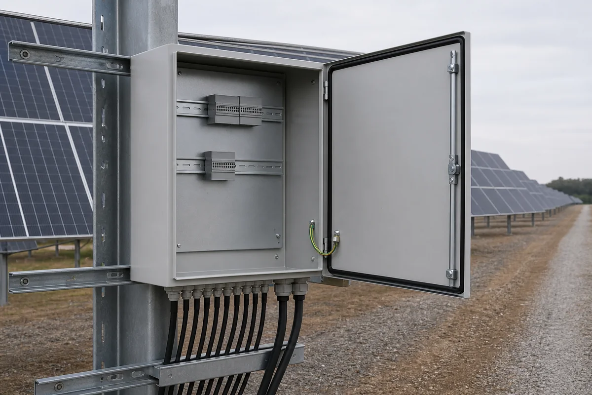
Standard Outdoor Box
Use when equipment envelope, wall or pole mounting and cable-entry pattern fit a catalog body without structural changes.
- Fastest selection route
- Confirm usable plate and gland area
- Customer controls internal electrical layout
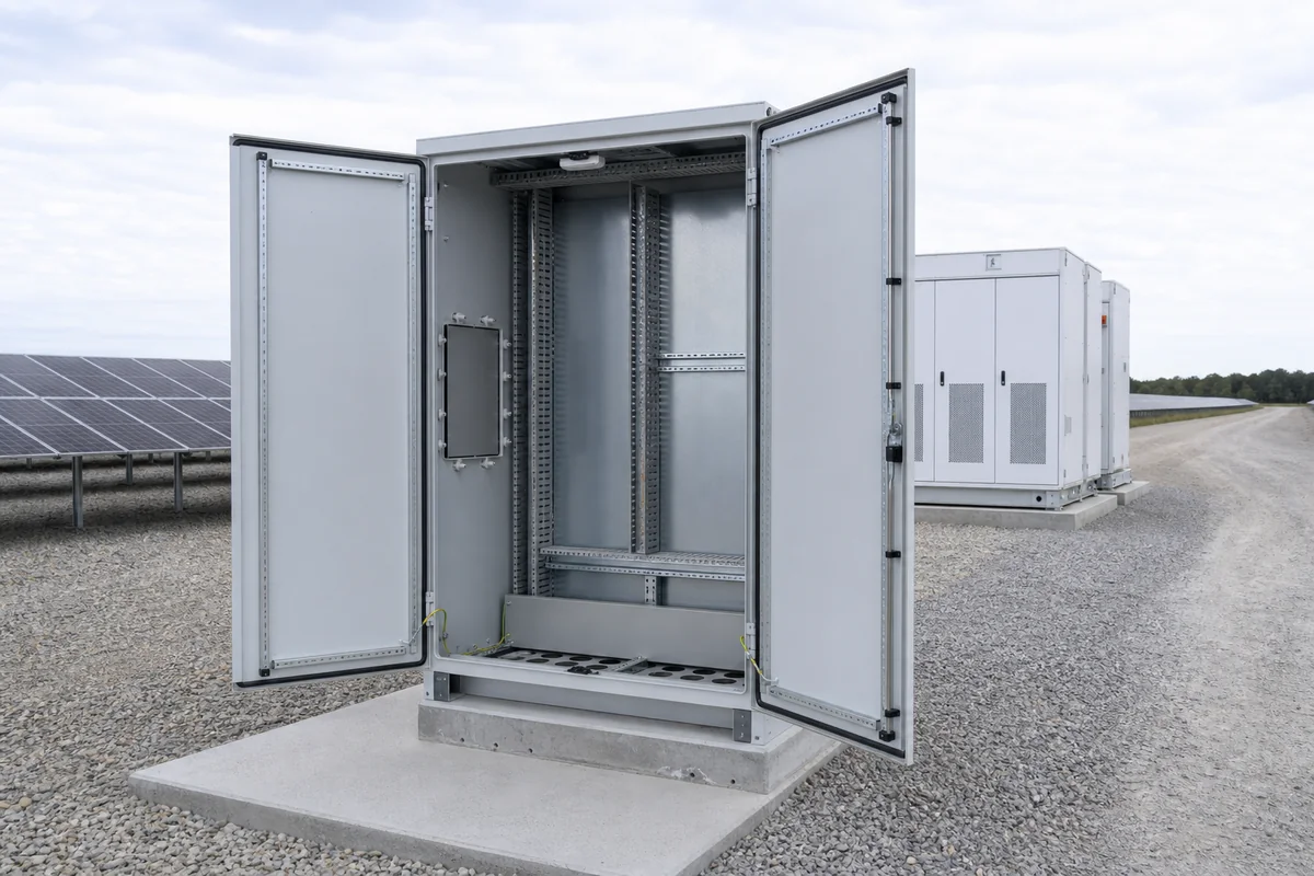
Modified Solar Project Enclosure
Use when a standard body needs a project backplate, gland plate, brackets, cutouts or coating direction.
- Controlled outdoor modifications
- Good for repeat string/site variants
- Approved entry and mounting drawings
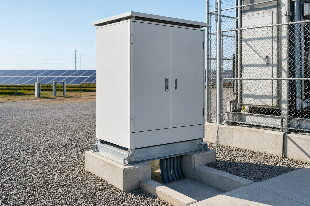
Fully Custom Outdoor Cabinet
Use when depth, equipment heat, multiple zones, base entry, doors or site mounting require a project-specific body.
- Complete four-gate review
- Custom structure and interfaces
- First-article CTQs from approved drawings
06 / BEFORE QUOTATION
What to confirm for an outdoor solar enclosure quote
State which equipment, site-exposure and cable-entry inputs are approved and which are still provisional.
Price the equipment and site interfaces, not an IP target alone
FN reviews actual equipment and installation data to define enclosure geometry, material and finish, openings, gland plates, brackets, maintenance features and requested records.
Subsystem & Equipment
Combiner, inverter-control or auxiliary role; devices, dimensions, heat and mounting.
Environment & Solar
Ambient range, direct sun, dust, rain, salt, contaminants and exposure duration.
Cable & Termination
DC/AC/communication counts, diameters, glands, bend radius and entry side.
Water Path & Openings
Bottom geometry, drainage, field modifications, accessory cutouts and sealing responsibility.
Mounting & Service
Wall, pole, skid, plinth or pad; height, door swing and technician access.
Commercial & Quality
Quantity, variants, target market, customer specification, CTQs, packing and date.
Gate 01 · Equipment Release
Approve subsystem role, device envelope, heat and mounting.
Gate 02 · Environment Release
Approve site exposure, material and finish direction.
Gate 03 · Entry / Water-Path Release
Approve cables, gland plates, openings, drainage and field-modification boundary.
Gate 04 · Site Release
Approve mounting, door direction, maintenance access and drawing revision.
Mechanical Details to Review
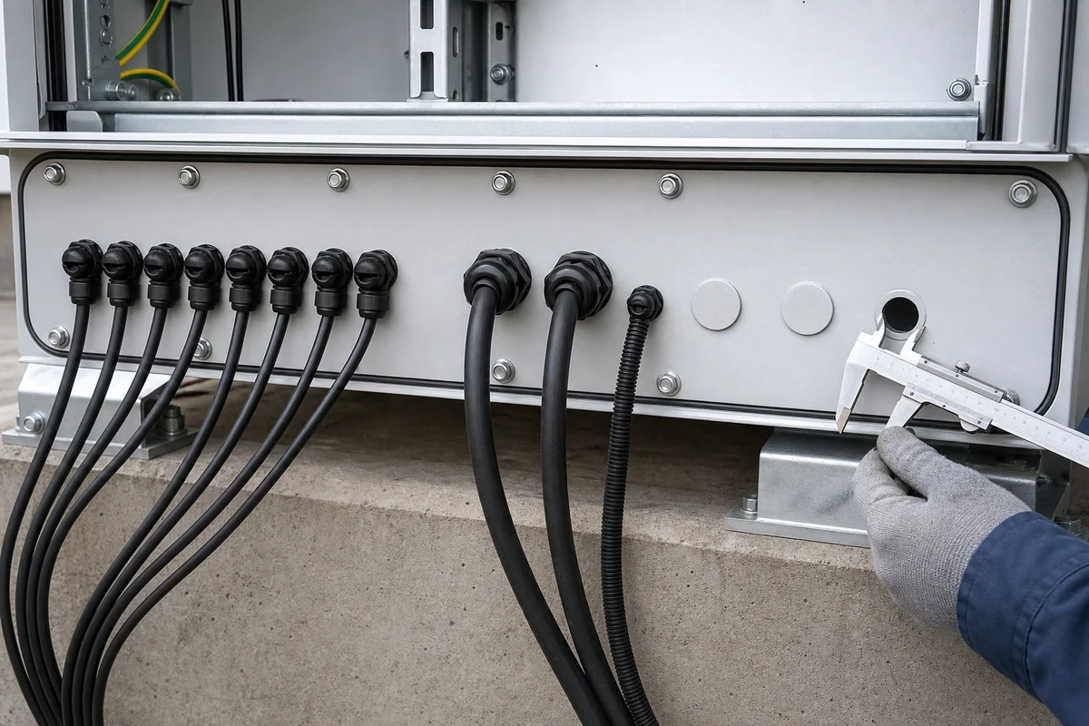
Gland Plate + Cable Entry
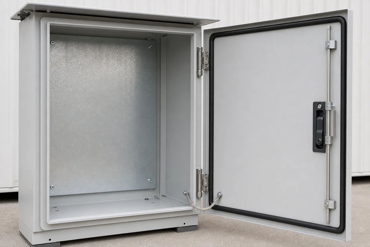
Door, Gasket + Drip Path
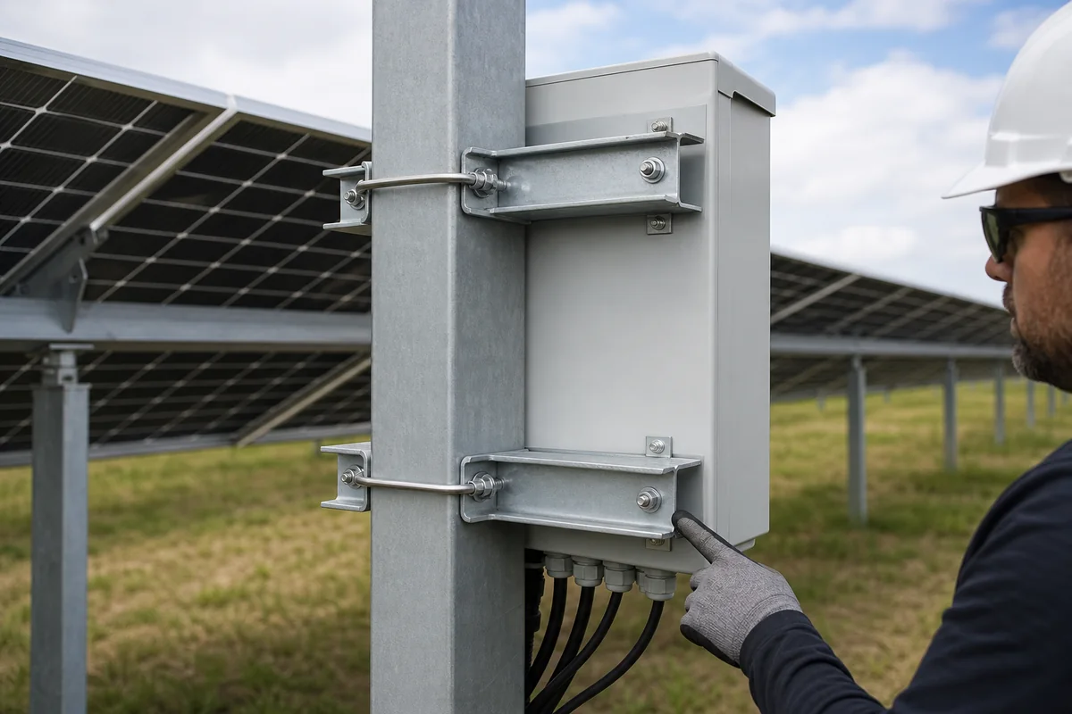
Wall / Pole Mount Interface
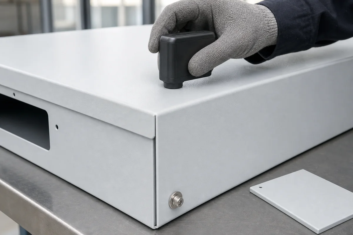
Outdoor Finish Detail
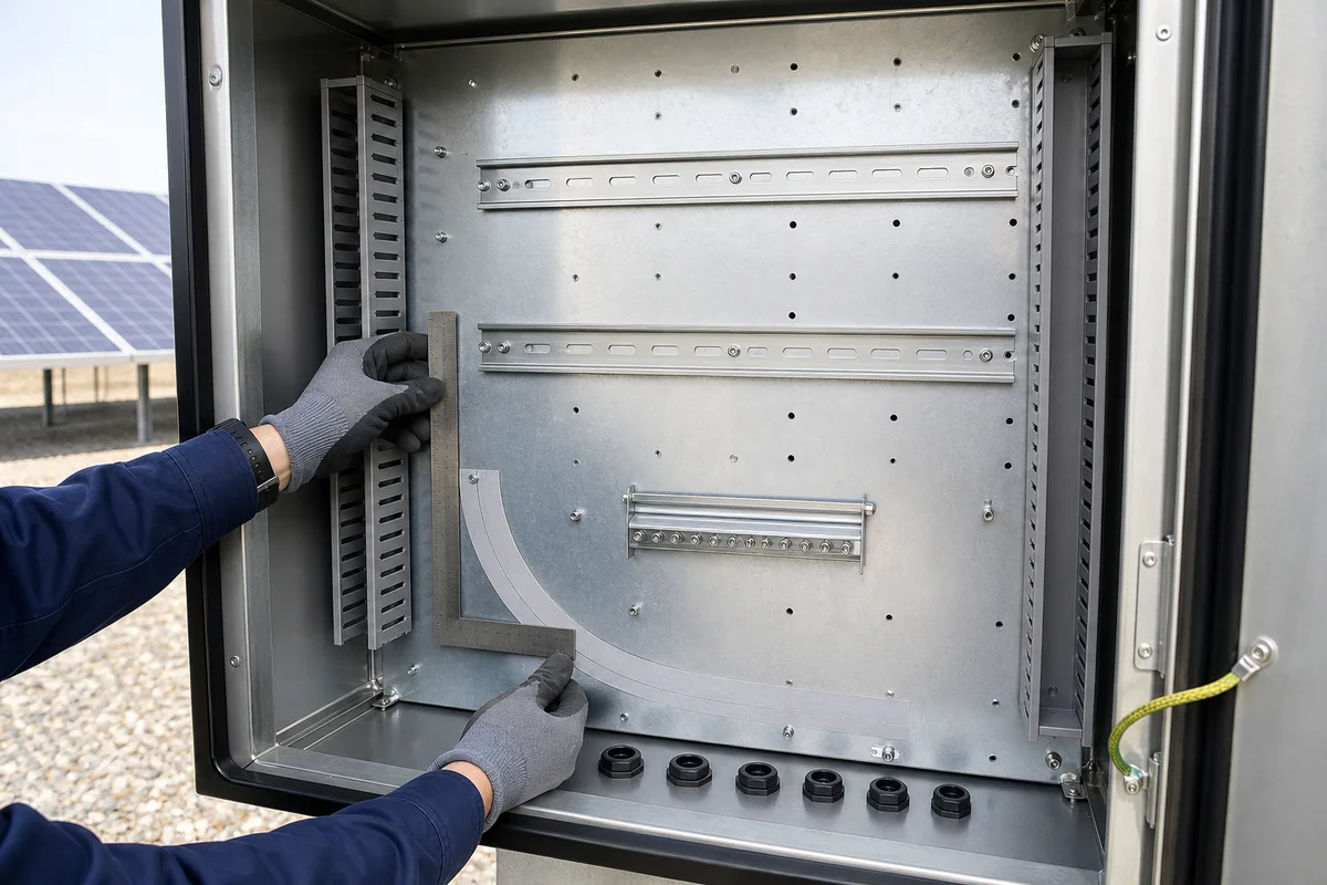
Backplate + Terminal Space
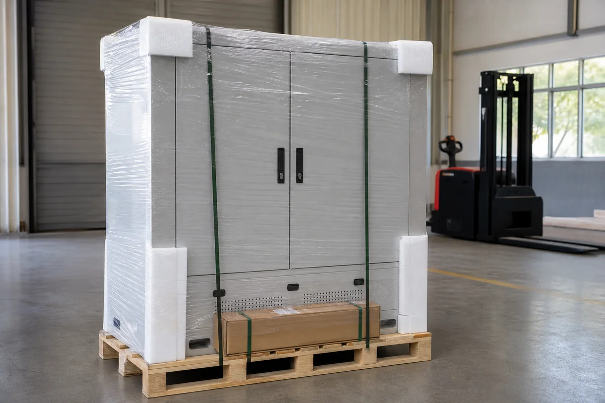
Outdoor Packing + Labels
08 / RESPONSIBILITY BOUNDARY
Solar Enclosure-Body Scope vs. PV Electrical-System Scope
Keep the empty or mechanically prepared enclosure separate from the complete wired and verified solar equipment.
FN Enclosure Manufacturing Scope
FN enclosure manufacturing scope:
- Body, door, mounting plate, gland plates, brackets, base/plinth and approved hardware.
- Approved holes, cutouts and mechanical provisions for selected equipment or accessories.
- Material and finish within the released specification.
- Wall, pole, skid or pad interfaces defined in the drawing package.
- Drawing-linked dimensional, visual and packing records as agreed.
Solar OEM / Panel Builder / EPC Scope
Solar OEM / Panel Builder / EPC Scope:
- PV electrical architecture, device selection, protection coordination and ratings.
- Wiring, grounding, terminals, cable glands and field connections.
- Cooling selection and final thermal validation.
- Site mounting verification, field sealing, drainage and installation.
- Commissioning and final product or system certification.
09 / PROJECT INFORMATION
Send the equipment layout and site conditions
Identify the equipment route first: combiner, inverter control or site auxiliary. Then use the matching equipment, cable-entry and mounting drawings below.
Project Information Checklist
- Subsystem role — combiner, inverter-control, communication or site auxiliary.
- Equipment list / layout — models, dimensions, mounting, weight and heat.
- Site environment — ambient, solar exposure, dust, rain, salt and contaminants.
- Cable schedule — DC, AC and communication counts, diameters and bend radius.
- Entry / gland plan — bottom, side or top entry; removable plates and field-opening boundary.
- Drainage / moisture concept — rain path, bottom geometry and responsibility.
- Mounting drawing — wall, pole, skid, plinth or pad interface.
- Maintenance direction — door swing, mounting height, access side and removal path.
- Material / finish — customer specification and environmental direction.
- Commercial inputs — quantity, variants, packing, target market and date.
Recommended First Package
- Subsystem and equipment layout
- Site / solar exposure data
- Cable-entry and gland plan
- Mounting and maintenance drawing
10 / FAQ
Outdoor Solar Enclosure FAQ
Questions specific to combiner, inverter-control and solar-site auxiliary enclosure-body projects.
Does FN supply a complete PV combiner box or solar electrical system?
This page covers enclosure bodies and approved mechanical interfaces. Electrical architecture, protection devices, wiring, ratings, commissioning and complete-product certification remain with the responsible solar OEM, panel builder or EPC unless separately contracted and verified.
What should be submitted for an outdoor solar enclosure quote?
Send the subsystem role, equipment list and layout, heat input, site exposure, cable schedule, gland plan, mounting drawing, maintenance side, material and finish, quantity and date.
Why is bottom cable entry reviewed together with drainage?
The bottom zone must accommodate glands, cable bend space, supports and a controlled water or condensate path. Reviewing them separately can create collisions or trapped moisture.
Can FN provide custom gland plates and equipment cutouts?
FN can manufacture approved openings and removable plates from released drawings. Device selection, cable gland selection, assembly and final ingress verification remain with the responsible party.
How should direct solar exposure be handled?
Provide site orientation, ambient range, equipment losses and the responsible party’s thermal concept. These inputs can affect volume, material and finish, shade or cooling provisions; final thermal validation remains outside the empty-body scope.
When should stainless steel or a coating system be considered?
Use actual exposure, contaminants, maintenance expectations and the customer specification—not only a broad location label. Final material selection should be documented in the approved project package.
Does an empty outdoor enclosure guarantee final IP or NEMA performance?
No. Installed equipment, cable glands, openings, assembly, field work and the complete verified configuration affect final performance.
START WITH THE EQUIPMENT AND SITE
Discuss the Equipment Layout, Cable Entry and Site Plan
Describe the enclosure in the contact form. Email drawings to info@fnenclosure.com with the project name and revision; we will review missing outdoor inputs before drawing approval.