

Cutting holes in plastic enclosures is practical when the opening is designed around the material, the surrounding structure and the component that will occupy it. The main risks differ: excessive cutting heat can smear or distort thermoplastics, while poorly cut glass-reinforced material can chip or delaminate. A neat opening also has to leave a suitable surface for the connector or gasket. Its diameter alone does not establish a sealed assembly. [68][51][235]
Begin with the component’s mounting drawing and the enclosure’s internal geometry. That combination tells you where material can be removed, which dimensions matter and whether the fixing can actually be installed.
Identify the material and obtain machining instructions
An ABS enclosure, a polycarbonate enclosure and a glass-reinforced polyester enclosure should not inherit the same workshop settings. OKW describes heat buildup, deformation and tool smearing when machining thermoplastics. Stahlin’s enclosure guidance identifies edge chipping and delamination when fibers are torn rather than cleanly sheared. These are different failure mechanisms, so a process that produces a clean hole in one material may be unsuitable for another. [68][51]
Use the exact enclosure material and model to obtain starting instructions. Material grade, reinforcement and wall geometry matter more than the broad word “plastic.” In a thin wall, the setup also has to hold the part without forcing it into a different shape while the hole is made. Protolabs’ machining guidance describes both tool and workpiece deflection as causes of dimensional and surface problems. [79]
The supplier’s instructions should establish the approved tool type and process limits. For example, Stahlin recommends sharp cutting edges and discusses carbide- or diamond-tipped tools; it warns that tools becoming dull can produce excessive chipping. For punching, Stahlin allows manual or hydraulic actuators for composite materials but does not recommend them for polycarbonate. Follow the guidance for the specific enclosure material even when the requested hole size is identical. [51]
For a new combination of material, wall and opening, make the first cut on a representative sample before processing the batch. The sample should show whether the tool exits cleanly and whether the wall returns to the intended shape after it leaves the fixture. A flat coupon can help establish cutting behavior, but it cannot reveal interference with a molded pillar inside the actual enclosure.
Machine the enclosure before installing electrical equipment. Include dust and chip control in the setup, using the compound supplier’s safety information and the workshop’s protective procedures.
Lay out holes and cutouts around supports and sealing surfaces
The hole center on the outside face is only part of the layout. Inside the box, the connector body, locknut and cable need space. A nut that fits geometrically may still be impossible to turn next to a rib.
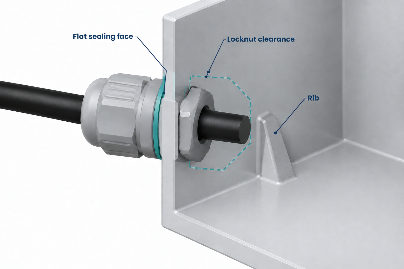
The external gland shoulder must sit on a suitable face, rather than partly crossing a corner or molded step.
Use a section view when an opening is close to a support or the lid joint. It makes conflicts visible that a flat face drawing can hide: an apparently clear cutout may remove the base of a mounting pillar or enter the surface on which the lid gasket seats. Manufacturer customization guidance identifies wall thickness, boss positions, gasket lands and door swing as related machining constraints. [131]
Choose dimensional references according to the assembly. For a panel-mounted switch on flexible wires, a modest position shift may have little effect. A PCB-mounted socket must align with the board supports as well as the opening. Bud Industries explains that two features can each be within their individual tolerances yet fail to fit because their deviations add together. A common datum ties the opening to the feature that actually controls assembly. [122]
A milled rectangular cutout will normally have internal corner radii. The mating device’s recommended opening should determine whether those radii are acceptable. Reducing them without a functional reason can force smaller cutters and additional operations; enlarging them without reviewing the device can prevent its body from entering. Protolabs describes this relationship between internal corners, tool size and machining work. [79]
SKILLQUBE’s simulator housings provide a useful application example. OKW reports machining openings for an iPad and cable connectors, and later supplying an iPad mounting plate with other internal pieces. The opening and internal support were developed as one assembly. The case does not provide finished-product sealing results, but it illustrates why the support location should be settled before the panel is cut. [286]
Control cracking, edge damage and exposed fibers
A sharp tool and a supported part reduce the temptation to force the cut when it stops cutting cleanly. Stahlin identifies dull tools as a common source of drilling failure and links delamination to tearing away excessive material or poorly sheared fibers. For sawed openings, it calls for a perpendicular tool and a consistent sawing action. Use those principles with the enclosure manufacturer’s actual process settings. [51]
Thermoplastic smearing needs a different diagnosis from a chipped fiberglass edge.
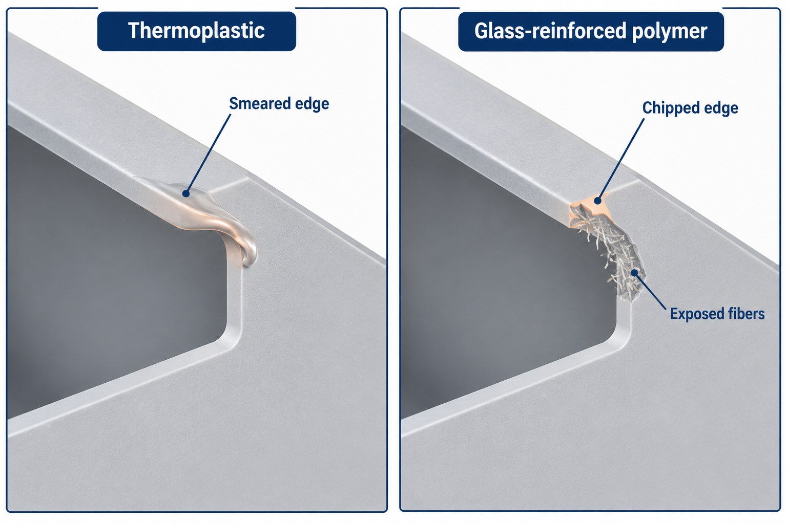
A glossy, distorted edge or material sticking to the tool can indicate excessive cutting heat. Increasing force may worsen the damage. With a fiber-reinforced wall, frayed fibers or separation beside the opening indicate that the cutting process has disturbed material beyond the intended boundary. Neither condition is resolved merely by enlarging the hole until the connector passes through. [68][51]
Repeated openings benefit from a defined locating fixture. Protolabs describes jigs and fixtures as tools for improving accuracy and repeatability. For an enclosure, the fixture should locate from the chosen references and support the wall without distorting it. A fixture that holds a bowed wall flat during machining can hide the free-state shape that the connector will encounter at assembly. [81][79]
Record the cut condition before fitting hardware. A bezel can conceal a chipped edge or a crack; it cannot demonstrate that the remaining wall is sound. Where glass fibers are exposed, follow the material supplier’s finishing instructions rather than applying an arbitrary resin or sealant. The repair or edge treatment must be compatible with the actual compound and the intended interface.
Check cable-entry and fastener interfaces after machining
A gasket works between mating surfaces. Burrs, loose fibers, a raised edge or a step beneath the sealing face can interrupt that contact. Protocase’s gasket guide describes the seal in terms of the surfaces it fills and the material selected for the environment. That is why a connector that fits the hole can still have an unsuitable sealing interface. [235]
For a cable gland installed through an enclosure wall, water can enter at the cable-to-gland seal or around the gland body where it passes through the wall. A removable gland plate adds a third potential path at its perimeter gasket. These cable-gland and gland-plate interfaces explain why a correct cable seal cannot compensate for a missing specified seal at the wall or uneven plate gasket. The component drawing should set the hole shape, permitted wall thickness, gasket position and fastening arrangement, with room on both faces and enough thread for the specified fixing after the wall and washer are in place.
Avoid using additional tightening force to pull a distorted surface flat. For a screw entering a molded boss, the screw diameter and the boss geometry determine how the plastic accepts the thread. Protolabs explains that an unsuitable hole or wall thickness can split the post; displaced plastic may also need space around the entry. The required torque therefore belongs to the specified screw-and-boss combination, not to a generic instruction to tighten securely. [106]
A practical post-machining record should connect observation to a decision:
| Observation | What it means for assembly |
|---|---|
| Hole or corner outside the component drawing | The component may bind, rotate or leave insufficient sealing coverage |
| Crack, chipping or separated fibers beyond the cut boundary | The remaining wall needs review before the opening is accepted |
| Burr or loose fiber beneath a washer | The sealing face is not ready for assembly |
| Nut, tool or cable interference | The layout needs revision even if the opening itself is dimensionally correct |
| Wall distortion after tightening | The interface or fastening method needs correction before sealing performance can be assessed |
Reassess the finished enclosure configuration
Machining a hole changes the enclosure’s protection boundary even when the plastic around it remains undamaged. After a gland, display or vent is fitted, sealing also relies on that component’s gasket, mounting surface and installation conditions. An accessory’s individual rating does not by itself establish the finished enclosure rating. The applicable record must cover the shell and installed interfaces together; an original empty-shell report remains useful, but cannot establish performance for modifications outside its stated configuration.
An effective first-article review uses the actual mating components. It confirms position and edge condition, then demonstrates that hardware can be fitted, the lid can close and the service connections remain accessible. Sealing or other required performance is assessed using the relevant agreed method; visual inspection alone only establishes the conditions it can reveal.
Retain the approved drawing revision, enclosure material and model, component part numbers, fastening instructions and inspection result with that sample. Those records make a repeat order reproducible and show when a later change requires another review. If the layout cannot retain sound material and usable sealing faces, reconsider the housing and modification route before producing more cutouts.
FAQ
Can fiberglass and polycarbonate enclosures use the same cutting method?
The material changes the likely failure. Excessive cutting heat can smear or distort thermoplastics, while a poor cut in glass-reinforced material can chip the edge or separate fibers. Stahlin permits manual or hydraulic punch actuators for composite materials but does not recommend them for polycarbonate. Use the instructions for the actual enclosure material and model rather than transferring settings from another box. [68][51]
Why can a correctly sized opening still fail to seal?
The connector gasket seals against the enclosure wall, not against the nominal hole diameter. Burrs, loose fibers, a raised edge or a molded step can interrupt contact beneath the sealing face. The cutout also has to suit the component’s wall-thickness and fastening requirements. A connector that passes through the opening is therefore not yet evidence of a sealed assembly. [235]
Why must a cutout be located from internal mounting features?
An opening for a PCB-mounted connector must align with the board supports as well as the outside face. Separate features can each meet their own tolerances yet fail to fit when their deviations add together. A shared dimensional reference controls that relationship; the layout must also leave room for the connector body, fixing nut, tools and cable. [122]
Sources
[51] Cutting & Drilling
[79] 6 Mistakes to Avoid When Designing Machined Parts
[81] Using 3D Printing for Complex Jigs, Fixtures, and Other Tooling
[106] Design Better Screw Bosses on Molded Parts
[122] How to Modify Enclosures to Get the Design You Need for Less Time and Cost
[131] Top Customization Options for Polycarbonate Enclosures
[235] Custom Gasket Guide