

Use the enclosure’s designed mounting points where they suit the component layout, and add a plate or bracket when several parts need a shared support. Choose the fastening method around the load and the expected servicing: a screw into a plastic boss can suit a lightly loaded assembly, while a metal insert provides a reusable thread. The insert still transfers force into the surrounding plastic, so its presence does not establish the load capacity of the enclosure. [74][98]
The mounting design has to connect the component to the installation through a continuous load path. A strong plate can still be attached to unsuitable pillars, and a well-supported PCB can still leave no room to unplug its cables.
Distinguish internal DIN rails from rail-mounted module housings
“DIN rail enclosure” can describe a small module housing that clips onto a rail. That housing supports its own PCB and terminals. An electrical enclosure containing a DIN rail is a different assembly: the rail carries components inside the outer box, and the box must carry the resulting load. OKW’s module guidance discusses rail clips and internal PCB supports, while Integra’s back-panel guidance describes rails mounted inside a larger enclosure. [69][130]
There is also a separate interface between the outer enclosure and the wall, machine or pole. A rail’s component capacity does not establish the outer box’s wall-mount capacity. Keep the three interfaces visible in the assembly drawing: component to rail, rail to enclosure support, and enclosure to its installation.
For a simple terminal layout, the existing internal supports may accept the required rail arrangement. A layout with mixed devices, several rail levels or a serviceable front panel may be easier to arrange on a mounting plate. Integra’s ABP-108 example uses a model-specific boss and T-rail system to position its panels; it demonstrates why the enclosure’s actual internal architecture matters more than a generic promise that it “accepts DIN rail.” [130]
Map component mass, load paths and mounting clearances
Start at the heaviest component and follow its support to the enclosure mounting points. A battery on a bracket, for example, loads the bracket, its fasteners, the mounting pillars and the enclosure wall behind them. Every interface needs a defined means of carrying that force.
Weight alone does not describe the demand on the joint. As a simple design illustration, place the same component close to a mounting plate and then on a long projecting bracket. The second position increases the leverage at the bracket attachment.
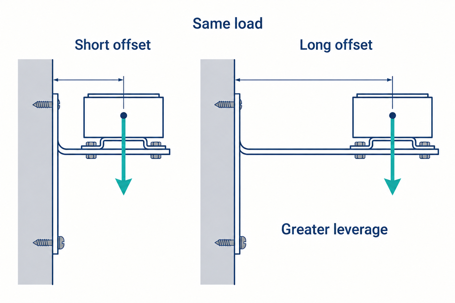
This is why a useful mounting layout shows both mass and center-of-gravity position, rather than a list of component weights alone.
Installation orientation also matters. A component supported from underneath on a bench can load its supports differently when the enclosure is wall-mounted. Transportation, vibration or repeated door movement may add loading that the stationary layout does not represent. Define those conditions before assigning an allowable load; a material strength value does not specify the geometry of this assembly. JLON’s SMC guidance separates strength, screw-holding performance, fatigue and creep resistance as different possible requirements for the finished component. [58]
Enclosure outside dimensions do not describe the space available for internal mounting. Wall thickness, internal hardware and mounting-plate position limit the usable envelope; the depth of door-mounted devices can conflict with components on the plate. Service space is additional: a screw needs room for its driver, a connector needs withdrawal clearance, and a cable needs room to bend without being forced against the cover. Enclosure sizing should accommodate those working clearances as well as the component footprints.
An OKW project for an unnamed medical-instrument customer illustrates this integration. Its internal aluminum brackets supported a display at the height needed to sit flush with the front panel. A separate plate fitted the rear molded pillars and carried the heavier battery; metal standoffs on that plate created additional mounting positions. The source describes a specific layout and construction, without publishing a general allowable load. The transferable lesson is to resolve display position, component support and available pillar locations together. [67]
Select bosses, threaded inserts, screws and mounting plates
A molded boss is a raised feature that can locate a component or receive a screw or insert. Its outside size is only one part of its performance. The pilot hole, wall around that hole and attachment to the enclosure wall determine how the fastener’s force is carried. Protolabs explains that adding material to strengthen a boss can also create an excessively thick molded region and cause sink or voids; ribs and gussets can provide support without simply making the boss solid. [98]
| Mounting method | Useful fit | Main limitation to resolve |
|---|---|---|
| Screw into a molded boss | Light components with a suitable screw and limited disassembly | Pilot-hole geometry, tightening method and remaining plastic thread |
| Threaded metal insert | A joint intended for repeated removal and replacement | Insert retention and the surrounding boss remain part of the load path |
| Mounting plate on designed supports | Several components that benefit from a common layout | Plate stiffness, its attachments and service-removal space |
| Internal bracket | A component needs a specific height, angle or offset | Leverage at its fixing points and support for the bracket itself |
The screw and boss should be designed as a pair. Protolabs recommends using the screw manufacturer’s hole and surrounding-wall guidance because an unsuitable combination can split the post. A counterbore may be needed to accommodate displaced plastic at the entry. Substituting a different screw diameter or thread form can therefore change the joint even if the screw head still fits the assembly. [106]
Metal inserts provide a metal-to-metal thread for repeated fastening, but they require a suitable installation method.
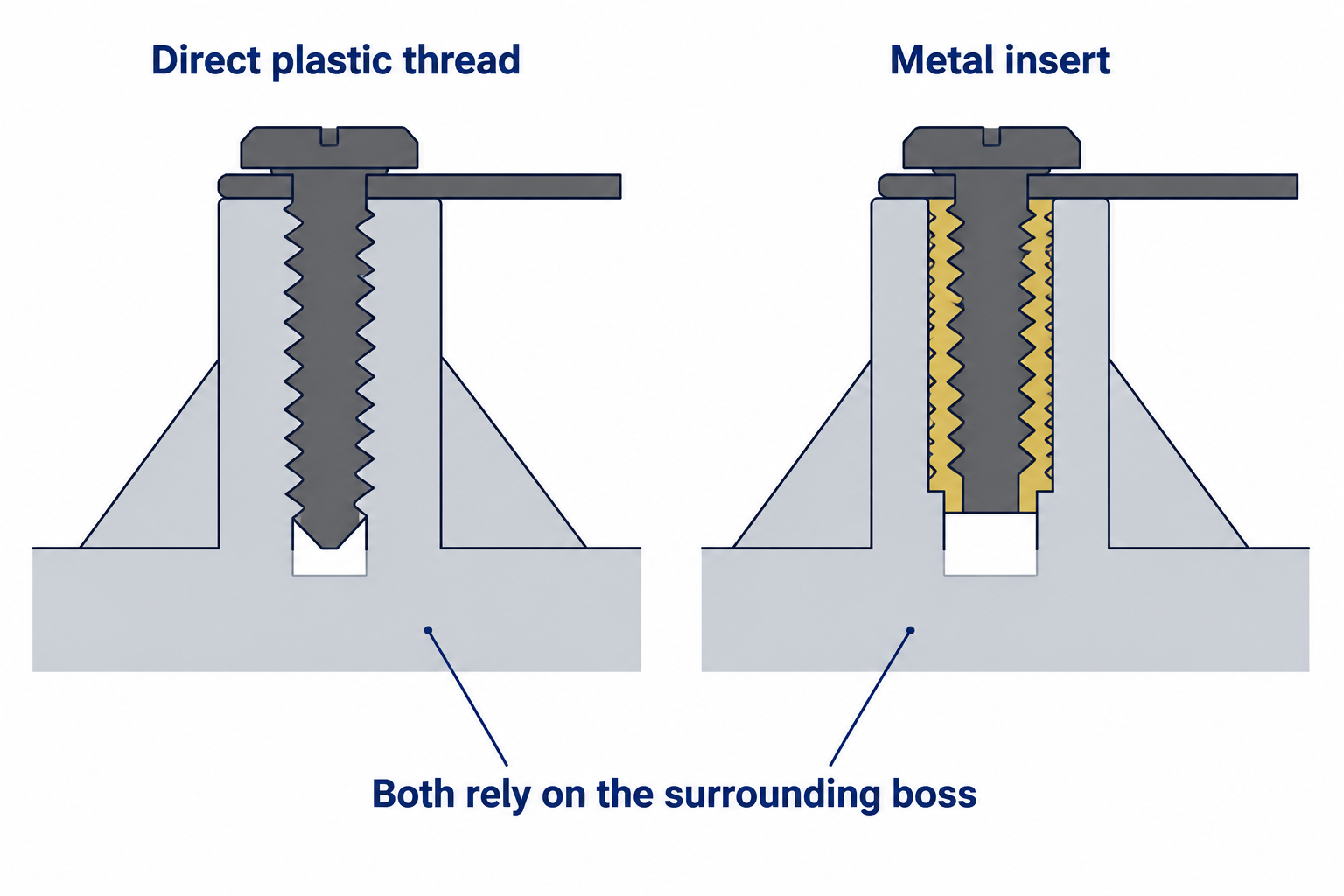
Heat staking and ultrasonic insertion locally melt thermoplastic around the insert, as Protolabs describes. That explanation does not authorize heat-setting an insert into an unspecified fiberglass compound. An SMC or other thermoset part needs an insert arrangement and process intended for that material. [107]
Check temperature, torque and repeated servicing
The temperature relevant to an internal mounting point is the temperature at that point during operation. Room temperature outside the box may not represent a boss beside a heat-generating component. A material’s heat-deflection temperature is also an unsuitable shortcut for an assembly load rating: Ensinger defines HDT as a specimen’s deformation under a specified bending load and describes it as a short-term material comparison. [214]
A continuously loaded support needs evidence covering the expected temperature and duration. JLON’s SMC specification guidance asks whether the component carries mechanical load at elevated temperature and separates continuous operation from short peaks. For a mounting system, the useful outcome is an allowable load for the intended conditions or a representative assembly validation, rather than an isolated material temperature figure. [58]
Tightening introduces another load. The assembly instructions should specify the fastener, insertion depth and torque appropriate to the actual joint. A screw that bottoms before clamping can feel tight while leaving the component loose; a joint overtightened to compensate for poor fit can damage the plastic. Resolve the geometry first, then establish the fastening method with the screw and enclosure supplier. [106]
Service frequency should influence the thread choice. Direct plastic threads can suit connections assembled infrequently; inserts offer a reusable metal thread when parts will be removed repeatedly. Protolabs’ fastening guide makes that distinction, while also explaining that an insert transfers force over an area of its host material. The surrounding boss must remain intact through the intended assembly and service operations. [74]
A removable mounting plate needs a defined way out of the enclosure in its intended service configuration. A wire duct can hide a fixing screw, and a projecting connector can catch the frame as the plate tilts. The removable mounting-plate review therefore includes access to fixings, disconnection after electrical isolation, support for the populated plate, and the complete withdrawal movement, including any components that must come off first. An empty-plate fit trial does not demonstrate maintenance access for the completed assembly.
Document the mounting interface for supplier review
An effective internal layout communicates the load as well as the hole pattern. Show the enclosure model and orientation, component masses and centers of gravity, support locations, plate or bracket geometry and the hole and cutout dimensions that control component alignment. Add the operating temperature at the mounting region and any relevant movement or vibration condition.
For each fastening interface, specify the mating parts and what the screw is expected to do. A fastener that clamps a removable bracket has a different service requirement from a locating pin or a screw used once to retain a PCB. Include screw length, thread type, engagement, insert identification where used, and the agreed tightening instruction. Model-specific details must come from the selected parts, rather than being filled in from a generic enclosure example. [74][106]
The first-article review can then answer concrete questions: whether the components sit in the intended positions, whether supports distort under the required test condition, and whether the service sequence works. Where sustained loading matters, the acceptance plan must state its duration and temperature. The approved result should identify the enclosure, material, hardware and drawing revision it covers.
Choose a different mounting arrangement when the proposed supports cannot demonstrate the required function. Moving a heavy part closer to the plate, sharing its support across suitable fixing points or selecting an enclosure with a more appropriate mounting system can address the load path. Changing only the screw leaves the rest of the load path unresolved.
FAQ
Do metal inserts establish an enclosure’s mounting-load capacity?
A metal insert provides a reusable thread, but the insert still transfers force into its surrounding plastic. The boss, plate or bracket, enclosure wall and installation fixings remain part of the load path. An allowable mounting load therefore needs support for the actual assembly and operating conditions; the presence of an insert alone does not establish it. [74][98]
Can heat-set inserts be used in an SMC enclosure?
A heat-setting method described for thermoplastics cannot automatically be applied to SMC. Heat staking works by locally melting thermoplastic around the insert. An SMC or other thermoset enclosure needs an insert arrangement and installation process intended for that material, rather than a thermoplastic procedure reused without support. [107]
Why does a mounting point need a temperature-specific load assessment?
A boss beside a heat-generating component can operate at a different temperature from the air outside the enclosure. A continuously loaded support also needs evidence covering load duration. Heat-deflection temperature is a short-term material comparison under a specified bending load; it does not establish the allowable load of the finished mounting assembly. [214][58]
Sources
[58] How to Specify Custom SMC: Technical Requirements and RFQ Checklist
[67] HOW EASY IS IT TO SPECIFY METAL BRACKETS INSIDE YOUR CUSTOMIZED PLASTIC ENCLOSURES?
[69] SPECIFY HIGH-QUALITY DIN RAIL ENCLOSURES FOR OPTIMAL PERFORMANCE
[74] Mechanical Fastening Methods for Metal and Plastic Parts
[98] Plastic Boss Design on Molded Parts
[106] Design Better Screw Bosses on Molded Parts
[107] Threaded Inserts with Heat Staking and Ultrasonic Welding
[130] ABP-108 Back Panel Customization Guide: Machining, T-Rails, DIN, and Swing Panel Options