
EV Charging Enclosures for AC Terminals and DC Power Cabinets
FN makes enclosure bodies for AC charging terminals, DC power cabinets and station auxiliaries. Before fabrication, review the display and payment cutouts, module layout, cable handling, cooling interfaces, foundation and service access against the charger design and site drawings.
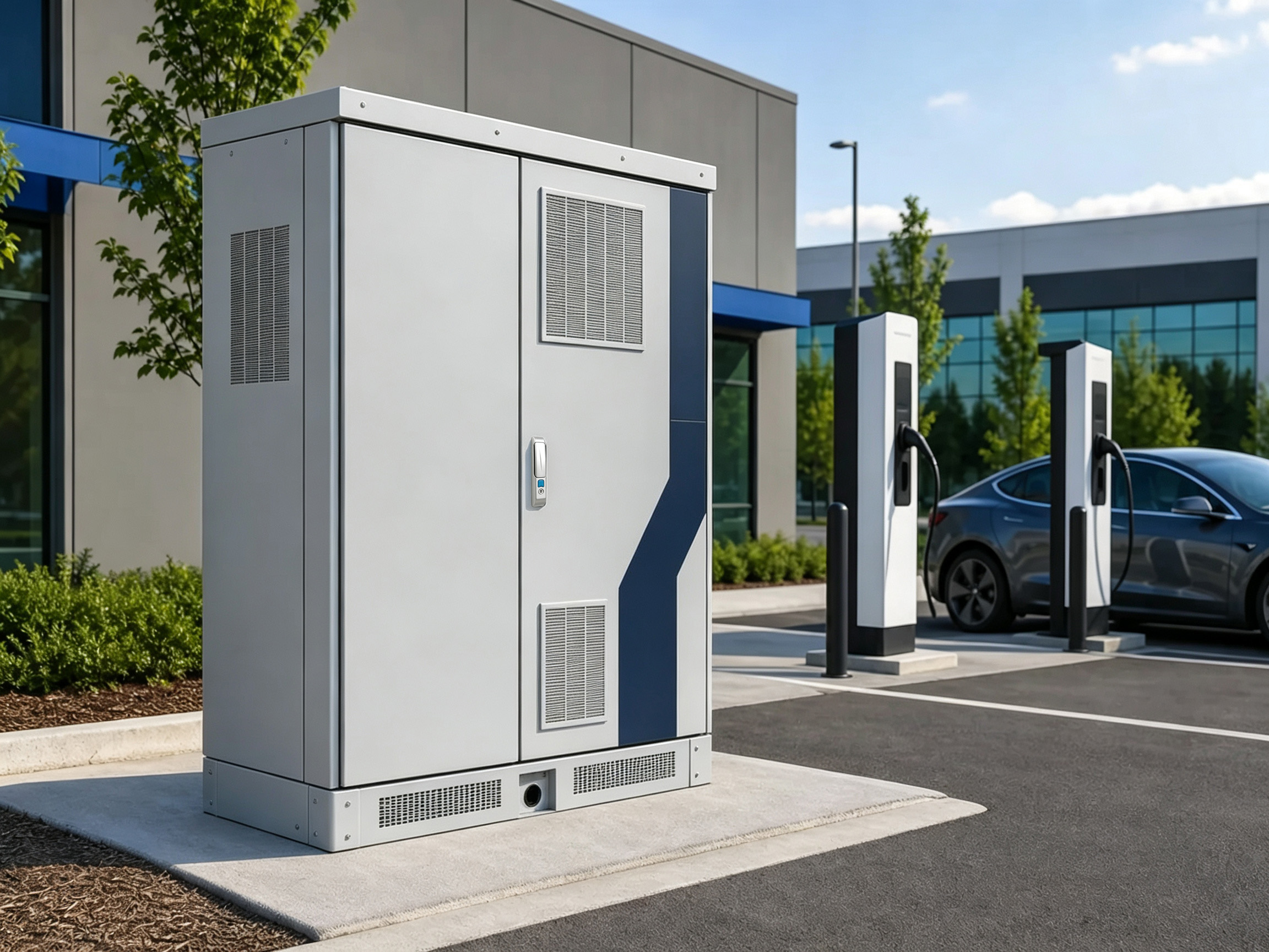
01 / SYSTEM POSITION
The enclosure role depends on the charger architecture
A public-facing AC terminal, a DC power-module cabinet and a station auxiliary cabinet need different cable routes, thermal openings, mounting and maintenance access. They are separate enclosure projects.
EV Charging Mechanical Interface Map
PUBLIC + EQUIPMENT INTERFACES
Display / Payment / Controls
Exact cutouts, rear depth, sealing interface, service access and visual alignment.
Power Modules + Controls
Equipment envelope, mounting, weight, heat and replacement direction.
Charging Cable + Holster
Exit, bend, strain, holster or bracket and public handling space.
SITE + SERVICE INTERFACES
Cooling + Module Service
Openings, filters or heat exchangers, door side and module removal path.
Foundation + Public Exposure
Base, anchors, lifting, bollards or vehicle exposure and access control.
Mechanical scope map · not a charger electrical design, payment system or complete site-safety validation
FN manufacturing scope
- Charger body, doors, panels, mounting plates, base/plinth and defined structure.
- Approved display, payment, control, cooling, cable and connector provisions.
- Approved brackets, holsters, locks, hinges and site-interface features.
- Agreed dimensional, visual, hardware, finish and packing records.
Boundary: FN does not design charger power electronics, electrical safety, payment or software, communication, charging protocol, cooling capacity, site traffic protection, installation, commissioning or complete-charger certification unless separately documented and verified.
02 / TYPICAL CONFIGURATIONS
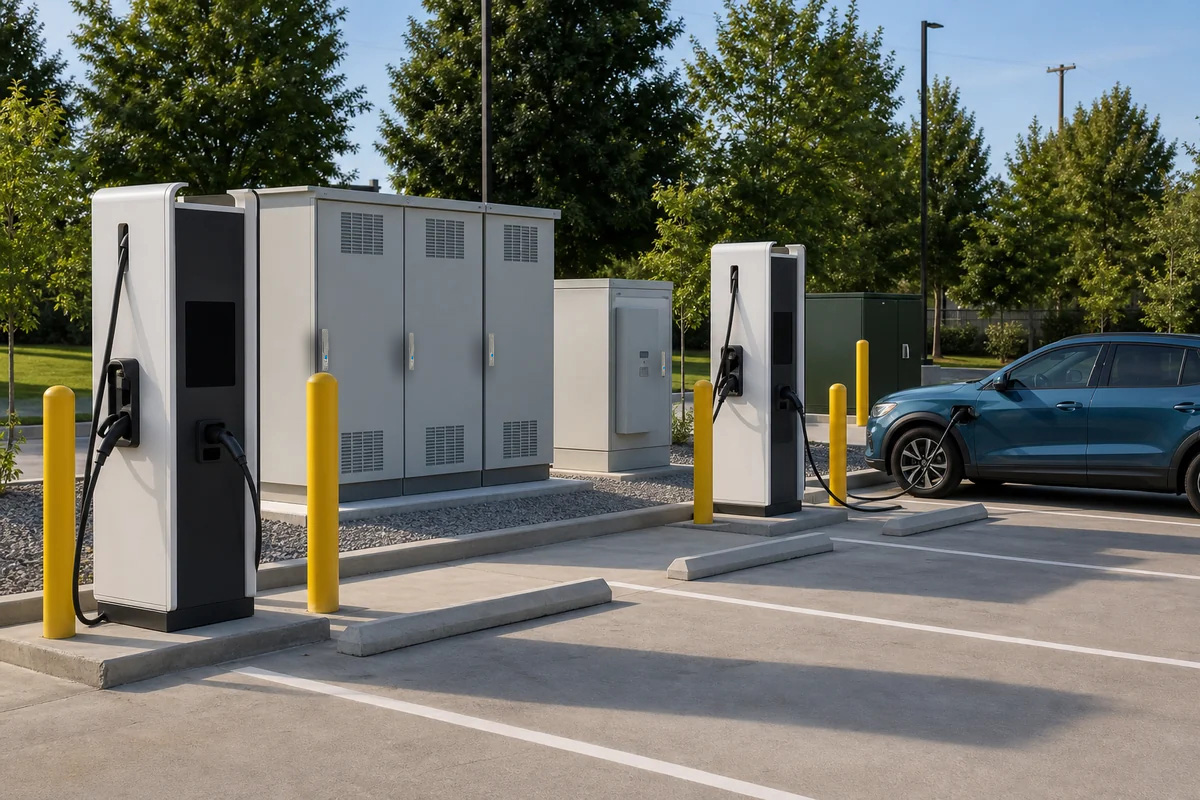
Three enclosure routes for AC, DC and site equipment
An AC public terminal, a DC fast-charging power cabinet and a site auxiliary cabinet have different public, thermal, cable and service requirements.
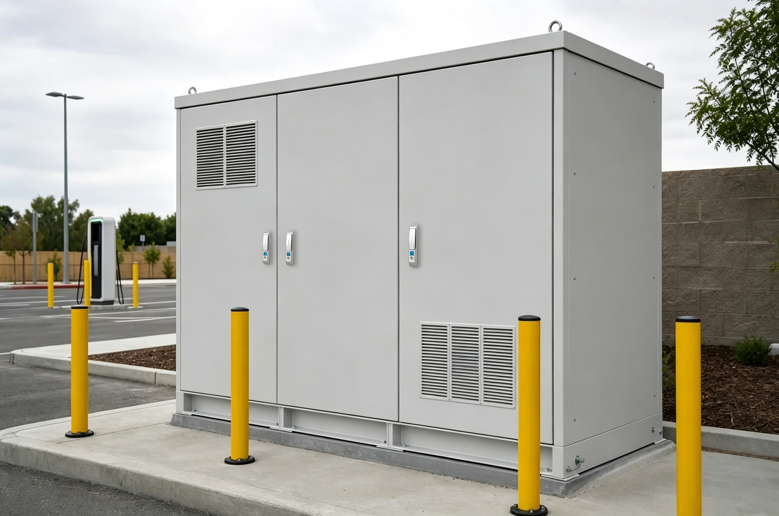
AC Charging Terminal Housing
Public-facing pedestal or wall-mounted bodies around controls, communication and charging interfaces.
- Display and control cutouts
- Cable exit and holster position
- Public contact and lock details
- Wall, pedestal or base mounting
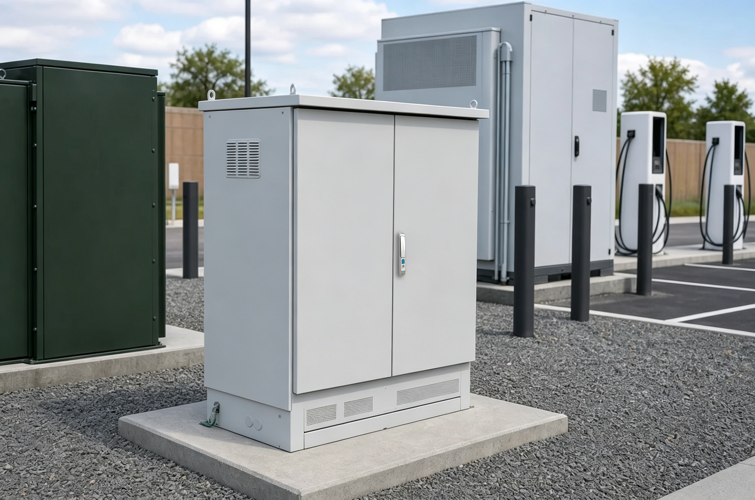
DC Fast-Charging Power Cabinet
Larger cabinets around power modules, cooling hardware and serviceable equipment zones.
- Module lineup and heat load
- Cooling interface and service side
- Heavy-device support
- Door and replacement path
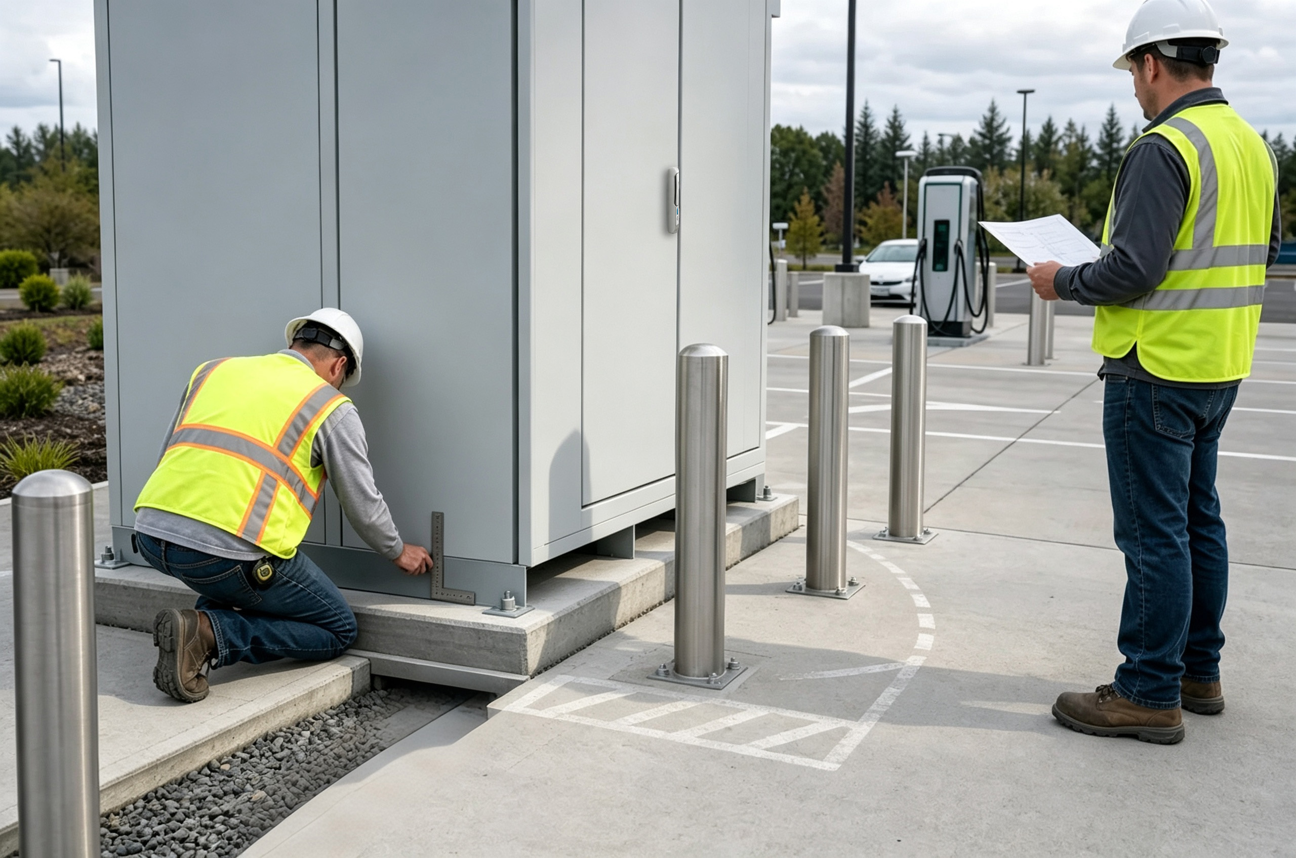
Site Auxiliary / Distribution Cabinet
Separate station cabinets for auxiliary power, communication or distribution equipment.
- Equipment and cable layout
- Foundation or pad interface
- Site access and security
- Responsibility separate from charger terminal
03 / FAILURE MODES
Public-Site and Service Failures That Change the Charger Body
Public contact, display and payment cutouts, cable handling, heat, foundations and module replacement all affect the body. A broad weatherproof claim does not define these interfaces.
Display or payment cutout uses nominal dimensions
Consequence: Visible misalignment, sealing conflict or field rework.
Mechanical decision: Cutout, studs, rear depth, support and front-panel geometry.
Required input: Exact vendor drawing, bezel, hardware and service envelope.
Public impact and exposed fasteners are not reviewed
Consequence: Panels, locks or interfaces are vulnerable at the site.
Mechanical decision: Panel stiffness, hinge or lock design, fastener exposure and base geometry.
Required input: Site risk, security specification and impact-protection concept.
Charging cable and holster geometry is added late
Consequence: Cable strain, awkward handling or door conflict.
Mechanical decision: Exit, bracket or holster, bend space and panel reinforcement.
Required input: Cable or connector model, reach, weight and operating path.
Power-module heat is declared after layout
Consequence: Cooling openings, cabinet volume or service side changes.
Mechanical decision: Airflow hardware, module spacing and removable panels.
Required input: Module loss data, ambient and selected cooling concept.
Foundation and anchor plan is provisional
Consequence: Base, door orientation or site installation conflicts.
Mechanical decision: Plinth, anchors, leveling, lifting and site clearance.
Required input: Approved foundation or site drawing and structural responsibility.
Module replacement path is blocked
Consequence: Service requires removing unrelated panels or site equipment.
Mechanical decision: Door width, rails, removable panels and access aisle.
Required input: Replacement sequence, tool space and module weight.
04 / DESIGN REVIEW MATRIX
Public Interface, Power, Cable, Thermal and Site Review Matrix
Translate charger architecture and site conditions into an enclosure body that can be fabricated, serviced and installed as intended.
Display / Payment
Interface: Cutout, bezel, studs, rear depth, cable loop, sealing interface and visual alignment.
Review question: Are exact vendor models and front elevations approved?
Release evidence: DXF or PDF + hardware pattern + approved front view.
Power Modules
Interface: Envelope, mounting, weight, heat, connectors and replacement path.
Review question: Which modules and variants are included?
Release evidence: Module schedule + layout + service sequence.
Cooling Hardware
Interface: Openings, supports, airflow direction, condensate and service side.
Review question: Who selects and validates the complete thermal solution?
Release evidence: Heat-load table + selected hardware drawing.
Charging Cable / Connector
Interface: Exit, bend radius, strain, holster, reach and public operating path.
Review question: Which cable and connector assembly is frozen?
Release evidence: Vendor data + operating envelope + bracket drawing.
Foundation / Site
Interface: Base, anchors, leveling, lifting, door direction, bollards and vehicle exposure.
Review question: What civil and traffic-protection plan applies?
Release evidence: Site GA + foundation drawing + responsibility matrix.
Security / Maintenance
Interface: Locks, hinges, exposed fasteners, module access, filters and replacement tools.
Review question: Who accesses each compartment and from what side?
Release evidence: Access-control specification + maintenance sequence.
05 / CONFIGURATION ROUTES
Select the Enclosure Route From Charger Architecture and Public Exposure
A modified cabinet can work for stable interfaces; custom public terminals and serviceable DC cabinets need a coordinated body release.
Modified Standard Cabinet
Use when a known body fits a non-public auxiliary or power function and only controlled openings, plates or base features change.
- Fastest route for stable interfaces
- Approved modification drawings
- Confirm site and service constraints
Custom Charger Enclosure Body
Use for public-facing AC or DC equipment with project-specific display, cable, cooling, doors and base interfaces.
- Coordinated public, equipment and site review
- Custom panels and structure
- First-article CTQs from approved drawings
Repeat OEM Charger Platform
Use when one released architecture supports controlled power, display or branding variants across production batches.
- Master body and option matrix
- Revision-controlled interface variants
- Finish, hardware and batch evidence plan
06 / BEFORE QUOTATION
What to confirm for an EV charger enclosure quote
List which display, equipment, cooling, cable and site drawings are approved and which are still provisional.
Quote the charger body from the actual architecture and site.
FN reviews module, operator-interface, cable, cooling, foundation and maintenance data to define body geometry, panels, supports, hardware, finish, CTQs and commercial assumptions.
Charger Route & Modules
AC terminal, DC cabinet or auxiliary role; module models, weights, heat and service.
Public Interfaces
Display, payment, controls, lighting or branding panels, locks and exposed fasteners.
Cable & Connector
Cable or connector model, exit, holster, reach, bend, strain and public handling.
Cooling & Maintenance
Losses, ambient, hardware, service side, filters and replacement sequence.
Foundation & Site Risk
Base, anchors, leveling, lifting, vehicle exposure, bollards and door clearance.
Commercial & Quality
Quantity, variants, finish or branding, target market, CTQs, packing and date.
Gate 01 · Architecture Review
Identify AC terminal, DC power cabinet or site auxiliary route.
Gate 02 · Public Interface Freeze
Approve display, payment, controls, cable or holster, locks and visible panels.
Gate 03 · Equipment + Site Freeze
Approve modules, heat, cooling, service path, base and foundation.
Gate 04 · Drawing Release
Freeze revision, finish, CTQs, responsibility notes and first-article evidence.
Mechanical Details to Review
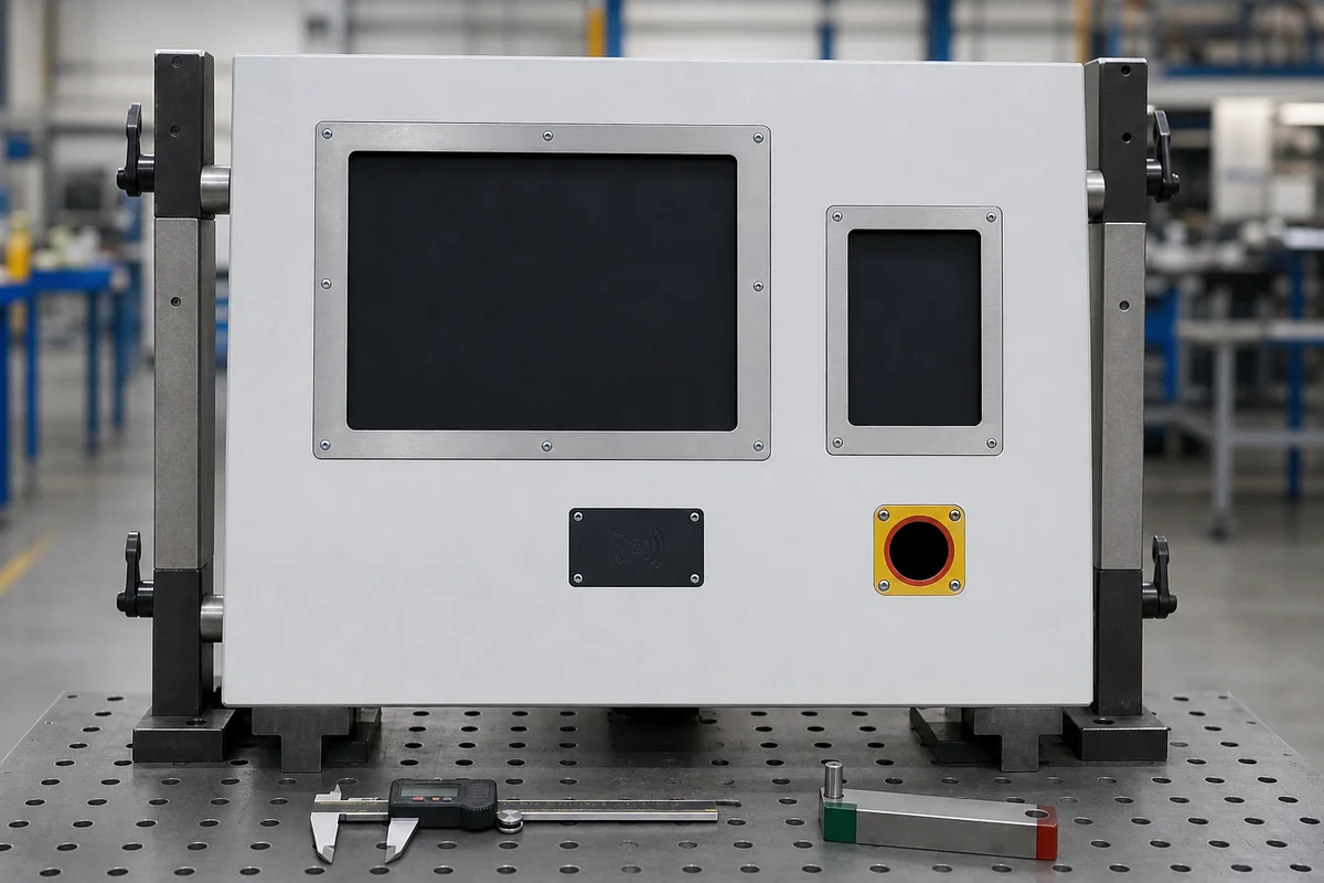
Display / Payment Cutout Check

Door, Lock + Exposed-Fastener Detail
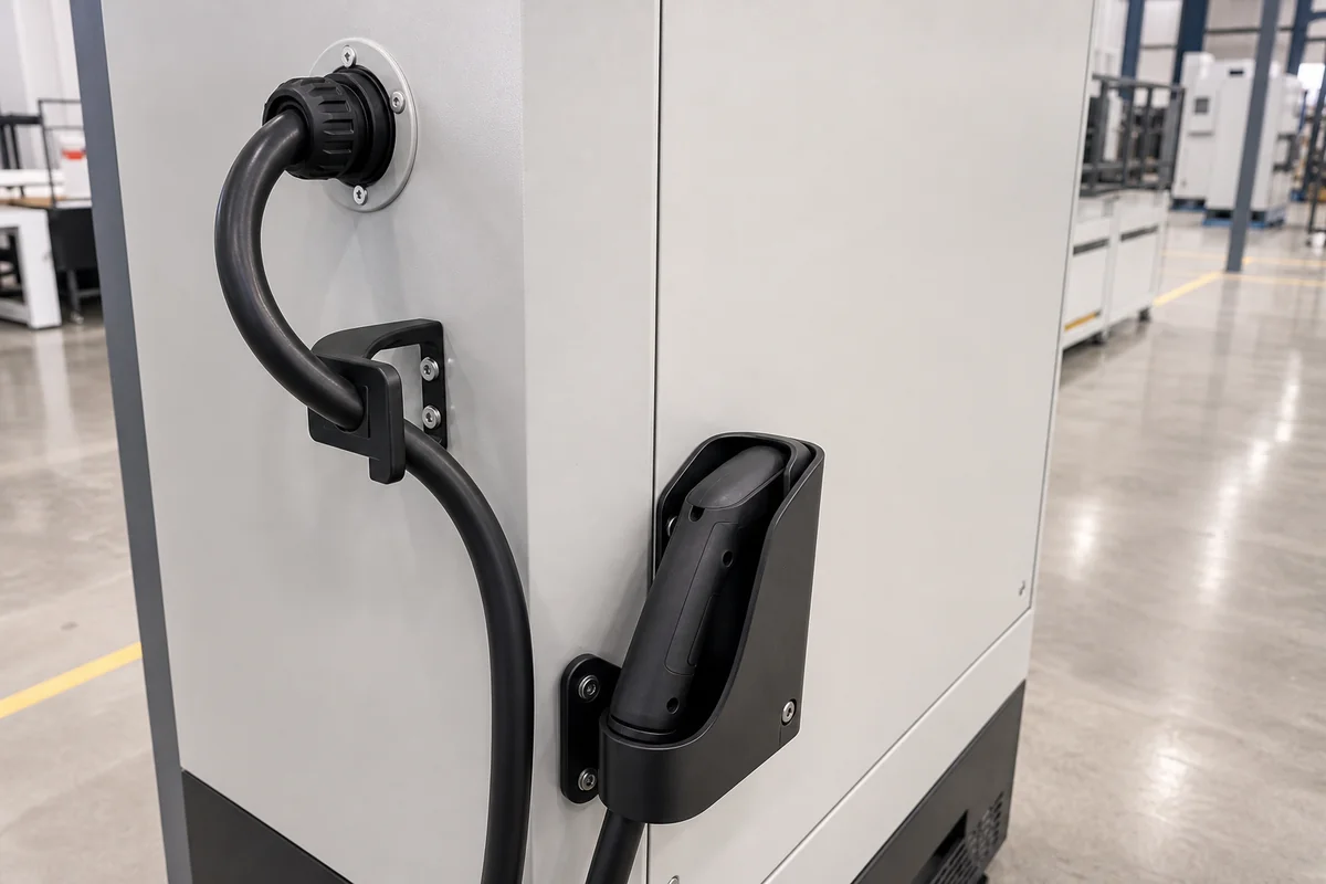
Cable Exit / Holster Bracket
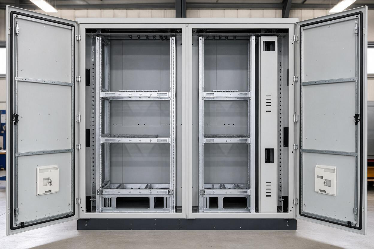
Module Rail / Support Detail
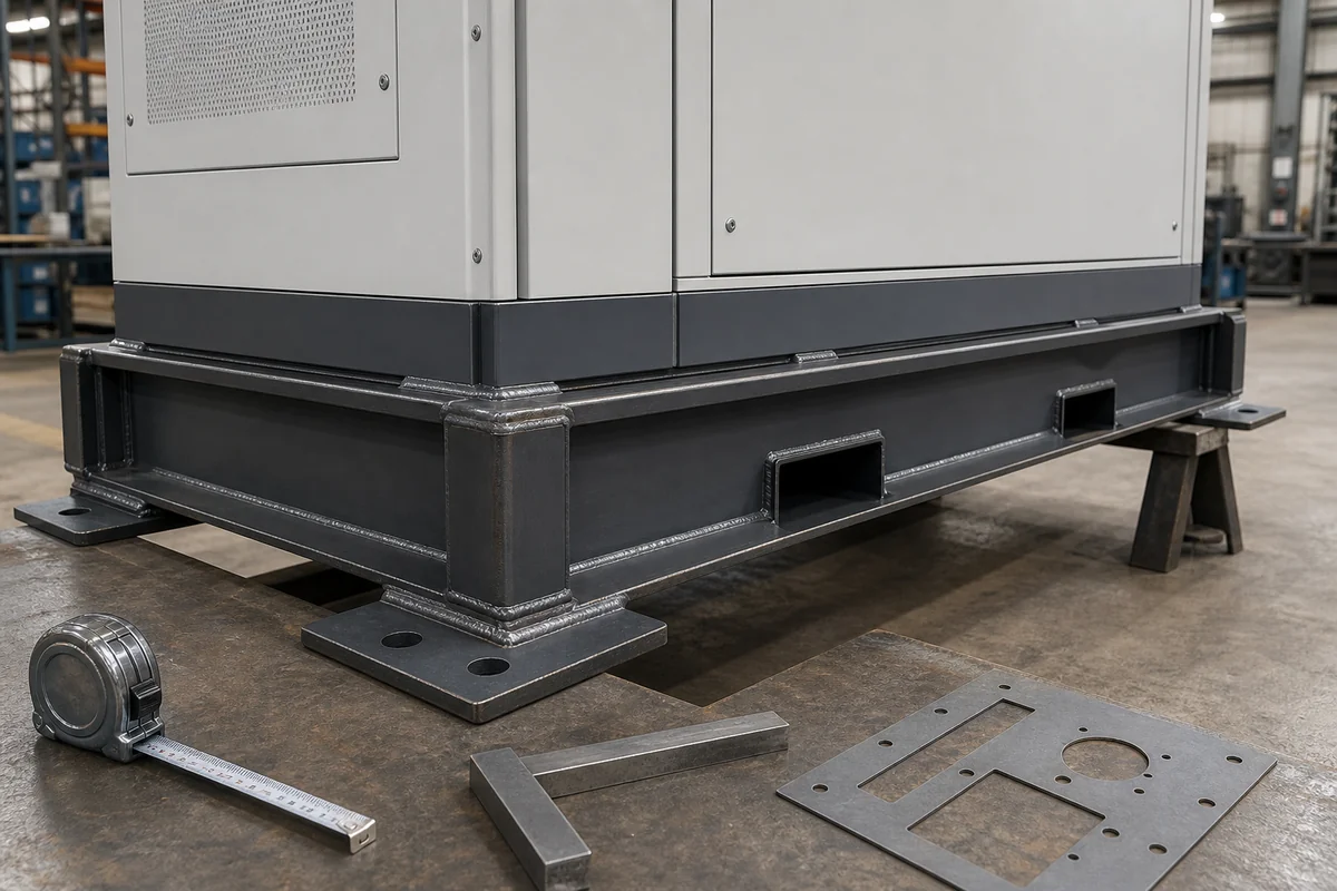
Base / Anchor / Lifting Interface
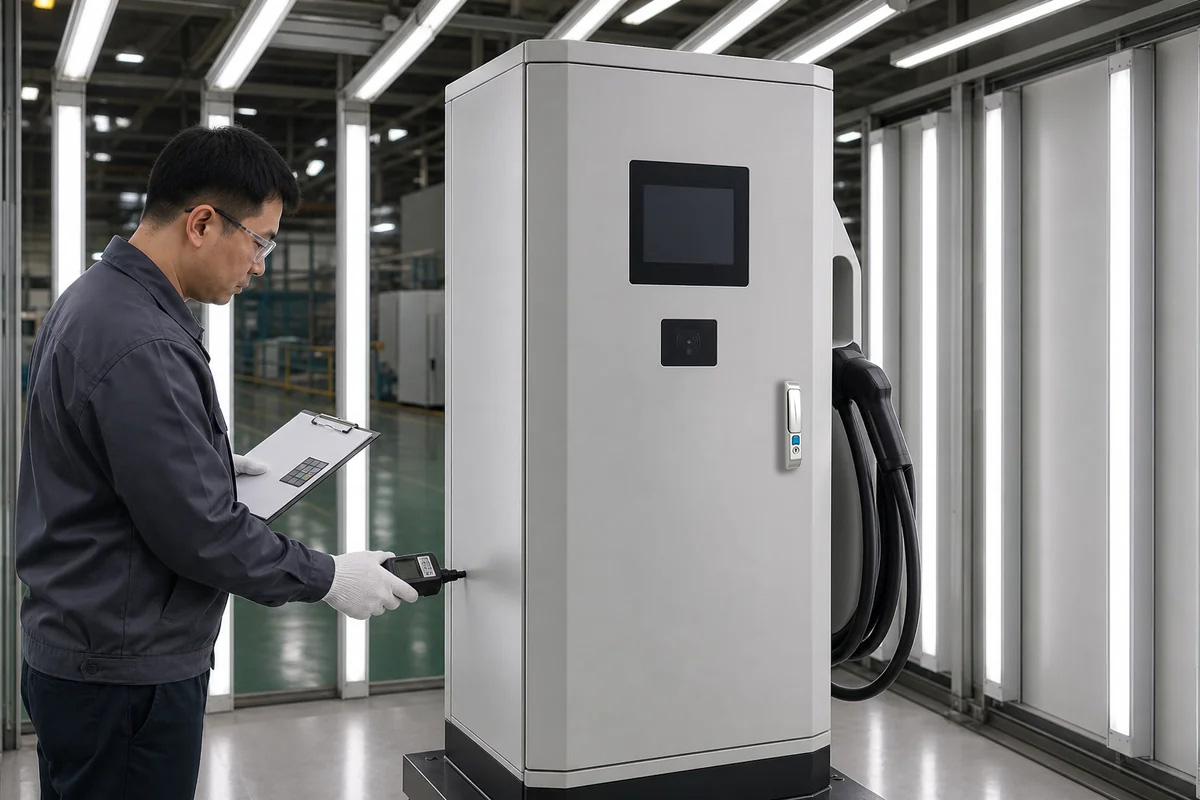
Finish + Public-Surface Inspection
08 / RESPONSIBILITY BOUNDARY
Charger Enclosure-Body Scope vs. Complete EV Charging System
A public-facing enclosure is only one part of the charger and site-safety system.
FN Enclosure Manufacturing Scope
FN enclosure manufacturing scope:
- Body, doors, panels, mounting plates, base/plinth and approved structure.
- Approved display, payment, control, cooling, cable and connector provisions.
- Approved brackets, holsters, locks, hinges and mechanical site interfaces.
- Material, finish, branding panels and hardware within the released package.
- Drawing-linked dimensional, visual, finish and packing records as agreed.
Charger OEM / Integrator / Site Contractor Scope
Charger OEM / Integrator / Site Contractor Scope:
- Power electronics, electrical architecture, protection, wiring and grounding.
- Payment, software, communication, charging protocol and cybersecurity.
- Cooling selection and final thermal validation.
- Cable or connector electrical and functional performance.
- Site civil work, traffic protection, installation, commissioning and final certification.
09 / PROJECT INFORMATION
Start with the charger layout and site conditions
Tell us whether the body is for an AC terminal, DC power cabinet or station auxiliary. Flag provisional display, module, cable and foundation drawings before requesting a fabrication-ready design.
Project Information Checklist
- Charger architecture — AC terminal, DC power cabinet or site auxiliary role.
- Equipment / module schedule — models, dimensions, weights, mounting, heat and replacement direction.
- Front interface drawings — display, payment, controls, indicators, branding and lighting panels.
- Charging cable / connector — model, weight, reach, exit, bend, strain and holster or bracket.
- Cooling inputs — losses, ambient, selected hardware, airflow and service side.
- Door / maintenance plan — access levels, locks, filters, removable panels and module sequence.
- Foundation / site drawing — anchors, leveling, bollards, vehicle exposure and door clearance.
- Material / finish — color, coating, hardware and public-surface expectations.
- Responsibility / compliance — system, site and final verification parties.
- Commercial inputs — quantity, variants, packing, target market and required date.
Recommended First Package
- Charger architecture and module layout
- Display / payment front drawing
- Cooling and cable-interface data
- Foundation and site conditions
10 / FAQ
EV Charging Enclosure FAQ
Questions specific to AC terminals, DC fast-charging cabinets and site auxiliary enclosure-body projects.
Does FN supply a complete EV charger?
This page covers enclosure bodies and approved mechanical interfaces. Power electronics, wiring, software, payment, communication, charging functions, commissioning and complete-charger certification remain with their responsible parties unless separately contracted and verified.
What is the minimum package needed for quotation?
Send the charger route, equipment or module layout, display and payment drawings, cable or connector data, heat and cooling inputs, foundation or site drawing, maintenance sequence, material and finish, quantity and date.
Can FN make display, payment and control cutouts?
FN can manufacture approved geometry and mounting provisions from exact vendor drawings. The selected device, sealing, wiring, software, payment and final functional validation remain with the responsible charger OEM.
How should charging cable and holster interfaces be reviewed?
Provide the exact cable and connector assembly, reach, weight, bend or strain limits, operating path and approved bracket or holster drawing.
What site information affects the base and doors?
Foundation and anchor pattern, leveling, lifting, bollards, curbs, adjacent chargers, vehicle exposure, pedestrian path, door swing and technician access can all change the body.
How are replaceable power modules accommodated?
Provide module size, weight, connectors, rail or support method, removal direction, tools and required service aisle. FN can manufacture the approved mechanical path; the OEM validates the service procedure.
Does the enclosure body guarantee final charger or site protection performance?
No. Installed modules, openings, cable interfaces, assembly, foundation, bollards, field work and complete-system verification determine final performance.
START WITH THE CHARGER ARCHITECTURE
Discuss the Charger Layout, Cutouts and Site Plan
Describe the enclosure in the contact form. Email drawings to info@fnenclosure.com with the project name and revision; we will flag missing mechanical interfaces for review.