

Quick answer
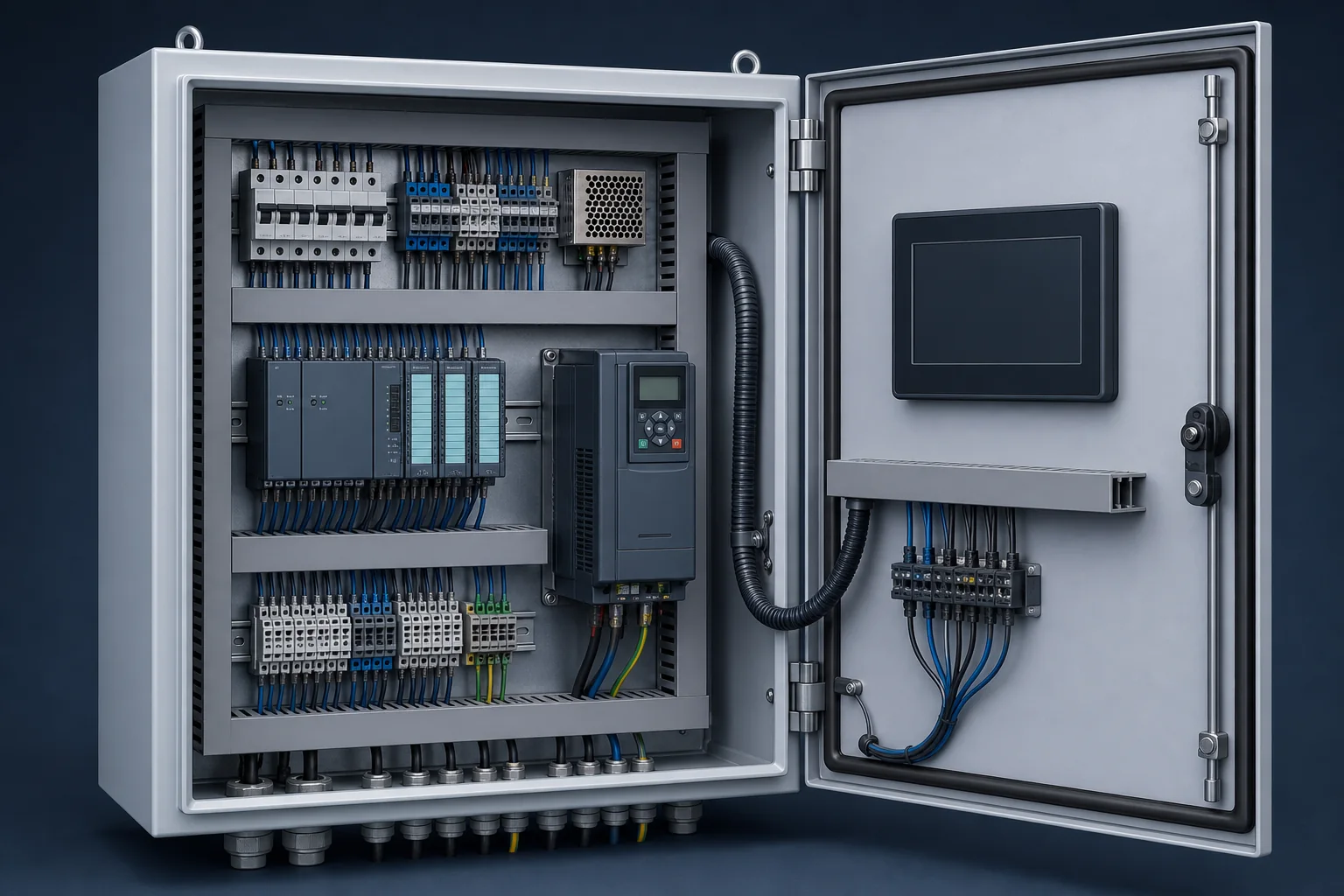
Electrical enclosure sizing should start with the usable mounting area, not nominal outside dimensions. Map the components, wiring and cable entry, door devices, service zones, planned additions, and heat sources. Check the complete depth stack and perform a thermal review. Choose the smallest standard enclosure that satisfies the combined constraints; consider custom fabrication when a fixed depth, entry, door, or installation boundary makes simple oversizing inefficient. Internal clearance and external working space are separate checks. Before RFQ or drawing release, run the Enclosure Constraint Stack.
The short version: enclosure sizing is not a box-volume problem. It is a constraint-stacking problem. The 7-Layer Enclosure Constraint Stack covers the component schedule, usable mounting area, wiring and cable entry, depth and door, service access, planned expansion, and thermal site conditions.
If you are comparing standard electrical enclosure sizes, treat each catalog size as a candidate—not the answer. Confirm the usable backplate, complete depth stack, cable bend space, door-mounted devices, service access, and heat load. If the same fixed interface still does not fit, compare a standard, factory-modified, modular, or custom path in the standard vs custom enclosure guide.

Why “just choose a bigger box” is not a sizing method
Consider a typical conversation during the preparation of a request for quotation (RFQ).
Buyer: “We need a 24 × 20 × 12 in. enclosure.”
Engineer: “What needs to go inside it?”
Buyer: “A programmable logic controller (PLC), several breakers, a power supply, terminals, and some cable glands.”
Engineer: “How deep is the power supply? Where do the cables enter? Is anything mounted on the door? How much heat does the equipment generate? Can a technician remove the PLC without disturbing the terminals?”
Those follow-up questions determine whether the enclosure works; the nominal size is only a starting point.
A larger enclosure may add mounting area, heat-dissipation surface, and expansion room, but it does not correct a poor layout. You can still have:
- a deep component that contacts the door;
- a cable entry that forces an unacceptable bend;
- a terminal block hidden behind wire duct;
- a gasket, hinge, or latch occupying assumed usable space;
- a hot variable-frequency drive (VFD) installed where airflow is restricted;
- a door-mounted device interfering with an internal component; or
- an enclosure that fits the parts but not the installation or maintenance area.
Illustrative failure chain: The components fit on the mounting plate. Then the largest cable cannot reach the lug without a tight bend. Moving the entry blocks the terminal service zone. Moving the terminal pushes the VFD toward the door-mounted display. The drawing still shows enough width and height, but the closed-door depth and airflow no longer work. The problem was not one missing dimension. The constraints had never been checked together.

A reliable process checks those constraints together before selecting the enclosure.
First, define what “clearance” means
Search results often mix several meanings of clearance. They are related, but they are not interchangeable.
| Clearance type | What it means | Who or what defines it | What to check | If it is missed |
|---|---|---|---|---|
| Component functional spacing | Space needed for cooling, operation, connectors, installation, and removal | Component manufacturer | Installation manual, orientation, ventilation, and service instructions | Overheating, blocked connectors, difficult replacement |
| Electrical spacing | Separation needed between live parts or conductive elements | Applicable product standard and design conditions | Voltage, pollution level, insulation system, product data, and applicable standards | Insulation or compliance risk |
| Wiring and bending space | Room for conductors, terminals, lugs, duct, entries, and bend paths | Cable, conductor, and terminal requirements, plus applicable code requirements | Conductor size, terminal instructions, bend radius, entry direction, and duct layout | Damaged conductors, stressed terminals, unbuildable wiring |
| External working space | Safe access around electrical equipment for operation and maintenance | Applicable electrical code and site rules | Adopted code, voltage, equipment condition, site layout, and AHJ requirements | Unsafe or noncompliant installation even when the enclosure itself fits |
For example, a panel can have adequate space in front of it for a technician but insufficient internal depth for a conductor bend. The reverse is also possible: a spacious internal layout does not prove that the installation has adequate external working space.
This guide focuses on the enclosure body and internal layout. External working-space requirements must be checked separately under the applicable electrical code, including Article 110.26 of NFPA 70, National Electrical Code, where adopted, together with local site rules and requirements of the authority having jurisdiction (AHJ).
Buyer: “The maintenance aisle is wide enough. Does that mean the enclosure clearance is acceptable?”
Engineer: “It may satisfy one external condition. We still need to check the spacing, wiring, bend paths, depth, airflow, and service access inside the enclosure.”
Keeping these definitions separate prevents room-level requirements from being misapplied inside the enclosure.

How to size an electrical enclosure from a component list
If you are asking how to size an electrical enclosure, apply the 7-Layer Enclosure Constraint Stack instead of jumping from a parts list to a catalog size:
- Build the component schedule. Record every internal, side-mounted, roof-mounted, and door-mounted item.
- Confirm the usable mounting area. Use the actual mounting plate and restricted zones from the enclosure drawing.
- Add wiring and cable-entry zones. Include duct, terminals, glands, conduit, connectors, and bend paths.
- Check the complete depth stack. Include mounting offsets, component depth, projections, cables, door devices, and hardware.
- Verify service and removal access. Make sure parts can be installed, inspected, adjusted, and replaced.
- Reserve planned expansion. Reserve space for named future devices, terminals, entries, and heat—not an unexplained percentage.
- Complete the thermal review and choose a standard or custom enclosure. Confirm that the mechanical, environmental, and thermal constraints work together.
This sequence provides the documented inputs for an electrical enclosure size calculation and final sizing decision.
Forward this guide to: the electrical designer who owns the component and wiring layout; the mechanical designer who owns the enclosure interfaces; the maintenance team that must service the equipment; the buyer preparing the RFQ; and the enclosure supplier reviewing manufacturability.
Build a component schedule before drawing the box
You do not need final CAD at the beginning, but you do need enough information to prevent the first layout from being based on guesses.
| Component input | What to record | Why it matters |
|---|---|---|
| Part and quantity | Manufacturer, part number, and quantity | Prevents missing or duplicated devices |
| Installed dimensions | Width × height × depth | Establishes the physical envelope |
| Mounting method and orientation | DIN rail, mounting plate, bracket, door, or side wall | Changes usable surface and heat transfer |
| Cable or connector direction | Top, bottom, side, front, or rear | Determines duct, terminal, and bend locations |
| Connector or terminal projection | Projection beyond the component body | Adds to required depth |
| Manufacturer-required spacing | Clearance above, below, at the sides, or in front | Protects cooling, operation, and access |
| Heat loss | Heat loss (W) at the intended load | Feeds the thermal review |
| Removal direction and tool access | Direction of withdrawal and required tool path | Shows whether the part can be serviced |
| Future change | Specific replacement, added module, or capacity change | Converts vague spare space into a planned reserve |
Ask suppliers for installed dimensions, not only body dimensions. A drive or power supply may need ventilation space, and a removable connector may project beyond the published body depth.
If you are sending the information to an enclosure manufacturer, include the component schedule with the preliminary drawing. That helps separate a fixed enclosure constraint from a layout preference that can still be changed.
Calculate usable mounting area, not nominal enclosure size
For the internal layout, the electrical enclosure mounting plate is the real starting surface. Components mount on a back panel, rails, brackets, or another internal structure—not on the outside catalog dimensions.
Usable area can be reduced by:
- wall thickness and formed returns;
- gaskets and sealing channels;
- hinges, locks, and latching hardware;
- mounting studs and edge zones;
- internal rails, brackets, or partitions;
- removable-panel clearances;
- door stays and bonding hardware; and
- the space needed for tools, wiring, and component removal.
A nominal 24 × 20 in. enclosure does not provide a 24 × 20 in. mounting surface. Confirm the actual plate size and restricted edge zones on the manufacturer drawing.
A simple usable-area check
Use this order for an early layout:
- Confirm the enclosure’s nominal width, height, and depth.
- Confirm the mounting plate width, height, position, and offset.
- Mark edge distances, studs, formed bends, hardware zones, and restricted areas.
- Place the components inside those usable boundaries.
- Reserve wiring duct, terminals, cable entry, and planned expansion zones.
- Place the deepest components and all door-mounted equipment.
- Recheck installation, wiring, removal, and closed-door conditions.
Do not subtract one universal number from every enclosure. The reduction depends on construction, hardware, mounting system, and the specific manufacturer drawing. A technical drawing is more useful than a general size chart when the layout is close to the limit.
Useful RFQ question: “What are the usable mounting-plate dimensions and the clear depth from the mounting surface to the closed-door hardware?”

Add wiring and cable-entry space before approving the layout
A component layout can look perfect until the wires arrive.
Wiring space depends on conductor size, insulation, number of conductors, terminal design, entry direction, bend requirements, and whether the wiring must be dressed into duct or a separate terminal area. Thick conductors cannot always turn through a tight corner just because the component bodies fit.
When planning wiring zones, mark:
- incoming and outgoing cable areas;
- cable-gland, conduit, or gland-plate positions;
- wire-duct width and height, plus cover-removal paths;
- terminal blocks, lugs, disconnects, and test points;
- connector removal direction;
- the largest conductor or cable bundle;
- the complete bend path; and
- areas that must remain clear for inspection or rework.
A cable gland is not only a hole in the enclosure. Its thread type and size, sealing range, cable outside diameter, armor requirement, locknut, washer, spacing, and installation access all affect the entry zone. For entry details, see the guide to cable glands and gland plates.
If the enclosure uses a removable gland plate, show its thickness and the distance from the entry point to the first terminal, lug, or bend. If cables enter from below, also check field access under the enclosure. A layout that works on a bench may fail when an installer must pull and terminate the real cable in a narrow opening.

Check the complete depth stack and the door
Width and height usually receive attention first. Depth is where many late drawing changes appear.
Do not check only the deepest component body. Build the complete stack:
Dimensional stack: mounting-plate offset + component body depth + terminal or connector projection + conductor bend allowance + door-device projection + assembly tolerance
This is a dimensional checking chain, not a universal formula. Each value must come from the relevant component, enclosure, cable, or project information. Then separately check hinge, latch, gasket, cable-movement, and service-access interference.
| Depth item | Question to answer |
|---|---|
| Mounting plate position | Where is the component reference plane relative to the enclosure back? |
| Component body | What is the deepest installed part? |
| Connector and terminal projection | What extends beyond the published body dimensions? |
| Wiring bend | Where must the cable turn, and can it do so without stress? |
| Door-mounted device | Does a meter, pushbutton, display, or operator project inward? |
| Door hardware and gasket | What space is occupied when the door closes? |
| Tolerance and movement | What dimensional variation or cable movement must the assembly accommodate? |
| Service tool and removal path | Is there enough space for tools, disconnection, and part removal? |
The door is part of the enclosure system. A display may be easy to operate from the outside but consume internal depth. A cable bundle may press against the door liner or seal. Hinges and latches may occupy corner space that looked available in a flat layout.
Before approving the enclosure, simulate the closed-door and service conditions:
- Does the door close without contacting components or compressing cables?
- Do internal parts interfere with door-mounted devices and their wiring?
- Can the operator use the door devices in the installed location?
- Can a technician remove the deepest serviceable component with the door open?
If any answer is unclear, the enclosure is not yet fully sized.

Treat future expansion as a plan, not a random percentage
Many guides recommend 10%, 20%, 25%, or 30% spare space. Those figures may be early planning heuristics, but they are not universal enclosure requirements.
Instead, identify what may actually change:
- one additional breaker;
- a larger power supply;
- extra terminal rows;
- new input/output (I/O) modules;
- a communication gateway;
- a second cable-entry group;
- a larger cooling device; or
- a future door-mounted operator.
Then reserve the kind of capacity that change needs. A blank rectangle on the plate is not enough if the future module also requires terminals, wire duct, heat dissipation, door access, and a cable route.
For a small control layout, a labeled spare zone may be more useful than a percentage. For a larger project, reserve a full DIN-rail section, a terminal expansion area, planned entries, and the corresponding thermal capacity.
Future-proofing also has a cost. A larger enclosure can increase material use, packaging requirements, shipping costs, wall footprint, door weight, and installation effort. The useful question is not “How much empty space can we afford?” It is “What change are we preparing for, and what interfaces will that change need?”

Thermal allowance is a calculation step, not empty space
If the enclosure contains power supplies, drives, transformers, relays, or other heat-generating devices, use their documented heat-loss or power-dissipation values, expressed in watts, in the thermal review. Total input power is not always equal to the heat released inside the enclosure.
Good electrical enclosure cooling calculations start with inputs rather than a box-size percentage. Collect:
- heat loss for each internal component;
- maximum and minimum ambient temperatures;
- maximum allowable enclosure-air temperature and component temperature limits;
- enclosure surface area exposed to air;
- mounting condition (wall-mounted, floor-standing, recessed, or other);
- enclosure material and finish;
- indoor or outdoor exposure;
- solar gain and nearby heat sources;
- sealed, vented, filtered, or actively cooled construction; and
- maintenance intervals, filter fouling, and altitude effects where relevant.
For a sealed passive enclosure, the basic relationship is straightforward: the internal enclosure temperature equals the ambient temperature plus the temperature rise produced by the actual heat load. Estimating that rise is the difficult part. Surface area, material, mounting method, air movement, heat-source location, and ambient conditions all affect the result.
Thermal-management references from AutomationDirect, nVent HOFFMAN, Rittal, Siemens, and Rockwell Automation use heat load, surface area, temperature rise, and cooling selection—not an empty-space percentage. Use them with component data; calculators support early selection but do not replace a detailed thermal study or field verification for demanding conditions.
Passive or active thermal management?
| Condition | First question | Typical direction |
|---|---|---|
| Low internal heat and moderate ambient temperature | Can the exposed surface dissipate the heat? | A sealed passive enclosure may be sufficient |
| Higher heat density | Where are the hot components and how will heat move? | Review layout, separation, surface area, and airflow |
| High ambient temperature | Can the enclosure remain below component limits? | Consider a heat exchanger, air conditioner, or another active method |
| Outdoor solar exposure | How much heat enters from the environment? | Review color, shading, orientation, exposed surface area, ambient temperature, and cooling margin |
| Dust, oil, or washdown | Can ventilation remain clean while maintaining the required protection? | Compare filtered ventilation, a heat exchanger, or sealed cooling |
| Low ambient temperatures or temperature cycling | Could moisture form during temperature changes? | Review heaters, vents, pressure equalization, and operating conditions |
For more detail, see Electrical Enclosure Cooling: Fans, Filters, Heaters, and Air Conditioners Explained and Why Condensation Happens Inside Outdoor Electrical Enclosures.
A more restrictive ingress protection (IP) rating or National Electrical Manufacturers Association (NEMA) Type requirement can change the thermal strategy because sealing may reduce natural airflow. Gaskets, door construction, and cable entries can also reduce usable space. Such a rating or requirement does not determine the enclosure size by itself. For a comparison of ingress-protection boundaries, see IP65 vs IP66 Electrical Enclosures.

When should you choose a standard or custom enclosure?
Common electrical enclosure sizes may be convenient catalog options, but they work only when the internal and installation constraints fit. Standard electrical enclosure sizes should be treated as candidates, not defaults. A standard enclosure is often the fastest choice when its mounting plate, depth, door layout, cable entry, thermal performance, and interfaces work without forced compromises.
If you are still defining the enclosure type and protection requirements, first review How to Choose the Right Electrical Enclosure for Your Project. Then compare the actual usable dimensions and interfaces.
| Controlling constraint | Standard enclosure is usually suitable when | Custom enclosure becomes reasonable when |
|---|---|---|
| Mounting area | The layout fits a documented catalog mounting plate | Moving to the next size creates substantial unused area or a conflict with the site layout |
| Depth | The full depth stack fits with service margin | One deep device, connector, or door component controls the box depth |
| Cable entry | Standard gland plates or conduit areas support the required route | Entry quantity, spacing, or position must align with fixed field interfaces |
| Door layout | The standard door layout accommodates the door-mounted operators and wiring | Door-mounted devices such as a human-machine interface (HMI), pushbuttons, windows, or interlocks require a controlled arrangement |
| Thermal-management equipment | Compatible accessories fit without blocking the layout | Cooling equipment and enclosure structure must be designed together |
| Future expansion | A documented spare zone fits in a catalog option | Future rails, entries, terminals, and heat capacity must be built into the design |
| Mating interface | Hole locations and tolerances can be adapted | The enclosure must mate directly with a machine, skid, frame, or assembly |
Do not choose custom fabrication merely because a larger standard box feels inconvenient. First determine whether the problem is a fixed dimensional interface, missing usable-dimension data, or a layout that can still be improved. Customization is most valuable when an unchangeable constraint controls the design and simple oversizing creates a new problem.

An illustrative RFQ conversation
Here is a composite example. It is not a project claim; it shows how a nominal request becomes a usable engineering input.
Buyer: “Please quote a 600 × 500 × 300 mm outdoor enclosure.”
Manufacturer: “What components are inside, and what usable mounting-plate area do you need?”
Buyer: “A VFD, PLC, 24 V power supply, breakers, terminals, and a display on the door.”
Manufacturer: “Please add the installed component dimensions, VFD heat-loss data, maximum ambient temperature, cable-entry direction, largest cable diameter, display rear projection, and removal space around the terminals.”
Buyer: “We may add two I/O modules later.”
Manufacturer: “Please mark the future modules, terminals, duct, and entry path on the layout, and annotate the added heat loss. A spare rectangle alone may not be usable.”
Decision: HOLD — do not approve the enclosure size yet. The proposed dimensions should not be approved until the depth stack, cable-entry path, door projection, service zone, and heat-loss inputs are confirmed.
Completing the Constraint Stack does not automatically require a larger enclosure. It reveals the controlling constraint and whether the next step is a layout revision, a larger standard size, custom fabrication, or more data.

A practical enclosure sizing worksheet
Before RFQ or drawing release, run the Enclosure Constraint Stack and complete this table. It converts the design into a documented input set instead of a catalog guess.
| Input | Your value | Confirmed by |
|---|---|---|
| Enclosure application | Indoor / outdoor / washdown / corrosive environment / other | Project owner |
| Target outside dimensions | Width × height × depth, if already constrained | Buyer or installation drawing |
| Usable mounting-plate dimensions | Width × height, edge zones, and plate offset | Enclosure drawing |
| Component schedule | Part number, quantity, installed dimensions, and orientation | Component manuals |
| Deepest internal component | Body depth + connector projection + bend allowance + service path | Component and cable data |
| Door-mounted equipment | Cutouts, rear projection, and internal wiring | Door layout |
| Largest cable or conductor | Outside diameter, terminal or lug requirements, bend allowance, and route | Cable and terminal data |
| Cable entry | Glands, conduit, gland plate, quantity, and direction | Electrical designer |
| Total internal heat loss | Heat loss (W) by component and total | Component suppliers |
| Ambient and environment | Maximum/minimum ambient temperature, solar gain, and nearby heat sources | Site conditions |
| Required protection | IP rating or NEMA Type requirement and validation basis | Project specification |
| Planned expansion | Named modules, terminals, entries, and added heat loss | Project owner |
| Service access | Removal direction, tool path and inspection zones | Maintenance team |
| Critical interfaces | Holes, bends, mating surfaces and tolerances | Drawing owner |
| Standard/custom decision | Selected option and the controlling reason | Buyer and enclosure supplier |
A useful worksheet records the detailed inputs. Use the accompanying FN Enclosure Constraint Stack Review Card to assign an owner, identify the evidence, mark each constraint Pass or Hold, and record the controlling decision.
Common sizing mistakes
Mistake 1: Using the outside dimensions as the mounting area
The catalog size does not account for every reduction in usable internal space. Use the mounting-plate and enclosure drawings.
Mistake 2: Treating external working space as internal clearance
The room around equipment and the space inside an enclosure solve different safety, wiring, thermal, and service problems. Check both separately.
Mistake 3: Adding a spare-space percentage without a change plan
Reserve rails, terminals, entries, duct, service access, and heat capacity for named additions—not just an empty rectangle on the drawing.
Mistake 4: Adding cooling after the mechanical layout is finished
Fans, filters, heat exchangers, air conditioners, heaters, vents, and thermostats require cutouts, airflow paths, service access, and sealing decisions of their own.
Mistake 5: Ignoring the door
Door-mounted components, hinges, latches, gaskets, bonding conductors, and cables pressing against the door can turn a fitting layout into a door that will not close or cannot be serviced.
Mistake 6: Treating IP or NEMA as a complete sizing answer
A protection rating addresses protection against specified environmental conditions. It does not establish the mounting plate, cable path, depth, service space, or thermal capacity.
Mistake 7: Giving an exact number without identifying its source
There is no universal “add six inches” or “leave 25%” rule for every enclosure. Use an exact value only when its source is a component manual, an applicable conductor or cable requirement, an applicable standard, a documented thermal method, or a clearly labeled project assumption.
What to send an enclosure manufacturer
A quote moves faster when the request contains the information that controls the enclosure. Send:
- the component list, quantities, and manufacturer part numbers;
- installed dimensions, orientation, connectors, and required spacing;
- the preliminary mounting-plate layout or marked-up drawing;
- the deepest component and complete depth stack;
- door cutouts, rear projections, and operator layout;
- cable-entry quantity, size, type, direction, and bend path;
- mounting plate, DIN rail, brackets, and internal partitions;
- total internal heat loss and maximum/minimum ambient temperatures;
- target material, finish, indoor/outdoor installation condition, and protection requirement;
- planned future modules, terminals, entries, and thermal capacity;
- critical installation and mating interfaces; and
- assumptions or dimensions that still need confirmation.
If you do not have a final drawing, send the component list and preliminary layout first. The manufacturer can help identify missing inputs, but the final selection still depends on the mechanical, wiring, environmental, and thermal information that controls the design.
FAQ
How much spare space should I leave inside an electrical enclosure?
There is no universal percentage for every project. Reserve space for identified future modules, terminal rows, wire duct, cable entries, service access, and added heat. A percentage can be an early assumption, but label it clearly and replace it with a project-specific expansion plan tied to identified devices before the layout is released.
Does a larger enclosure always run cooler?
No. A larger enclosure may increase surface area and layout freedom, but temperature still depends on component heat loss, ambient conditions, exposed surface area, mounting method, material, solar gain, sealing, and the cooling strategy. Perform a thermal review rather than assuming empty volume guarantees lower temperature.
Is NEC working clearance the same as internal enclosure clearance?
No. NEC working-space provisions concern safe access around electrical equipment. Internal clearance concerns component spacing, conductor bends, cable entry, ventilation, door interference, and service access inside the enclosure. Confirm the applicable external code requirement and the internal layout independently.
How do I calculate heat load inside an enclosure?
Add the internal component heat-loss values using manufacturer data, then evaluate ambient temperature, the maximum allowable enclosure-air temperature and component limits, enclosure surface area, mounting condition, material, solar exposure, and cooling method. Do not substitute total equipment input power or a fixed spare-space percentage for documented component heat-loss data.
Should I use a standard enclosure or request a custom enclosure?
Use a standard enclosure when the usable mounting area, complete depth stack, door layout, cable entry, thermal performance, service access, and installation interfaces all fit. Consider custom fabrication when one fixed constraint controls the design and moving to a larger standard box creates avoidable space, access, weight, or interface problems.
What information should I include in an enclosure RFQ?
Send the component schedule, preliminary layout, usable mounting area, deepest component, door devices, cable-entry plan, heat-loss data, ambient conditions, protection requirement, planned expansion, and critical interfaces. Identify which values are confirmed and which remain assumptions so the supplier can respond while keeping the remaining assumptions visible in the quote.
Final takeaway
A useful enclosure sizing decision produces more than a nominal W × H × D. It confirms that the usable mounting area, wiring routes, depth stack, door system, service access, planned expansion, thermal performance, protection requirement, and installation interfaces work together.
Before RFQ or drawing release, run the Enclosure Constraint Stack. Complete the FN Enclosure Constraint Stack Review Card, resolve every Hold item, and record the controlling constraint.
Need help checking a layout?