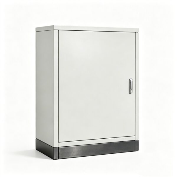
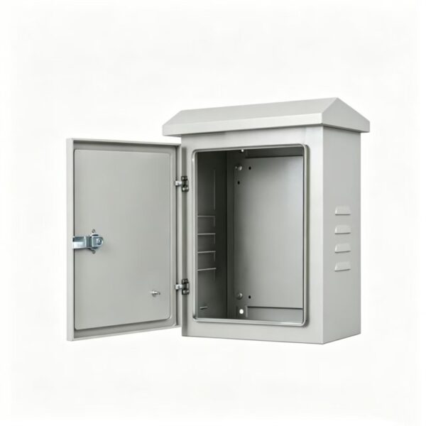
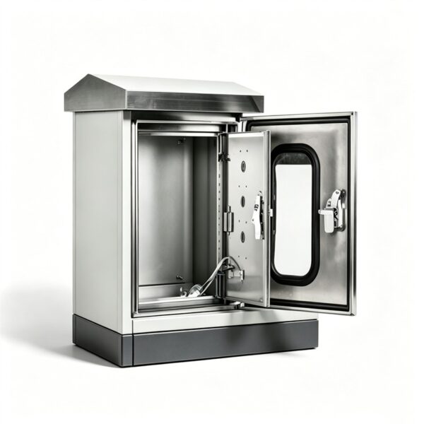
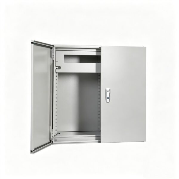
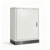
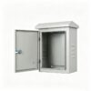
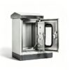
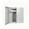
Wall-Mounted Electrical Enclosures
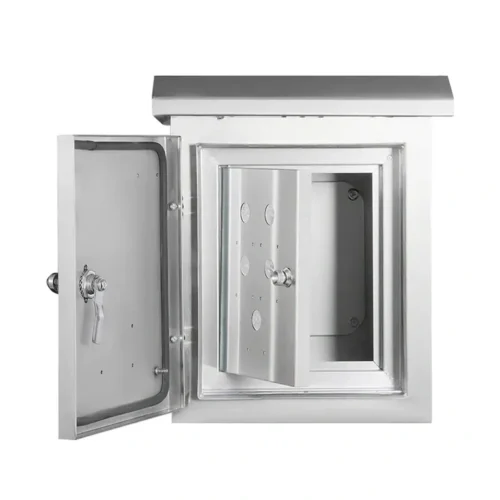
A wall-mounted enclosure must carry the installed load, open without collision and keep cable entry clear of the mounting surface.
- OEM format: Single-door, double-door and drawing-defined wall-mounted bodies.
- Project focus: Wall brackets, mounting plate, door swing, component depth, cable entry and maintenance clearance.
- Material route: Carbon steel, galvanized steel, stainless steel, aluminum, or drawing-specified material.
- Quotation basis: Drawing, environment, interfaces, quantity, evidence and supply boundary must be confirmed.
DRAWING-BASED OEM PROJECT
Wall-Mounted Electrical Enclosures for mounting centres, installed load and door operation
A wall-mounted enclosure must carry the installed load, open without collision and keep cable entry clear of the mounting surface.
Overall dimensions, door arrangement, mounting method and usable access are set by the approved drawing.
Review the wall interface, installed load, door swing, cable route and service clearance together.
Choose material and finish after reviewing indoor or outdoor exposure, corrosion, cleaning and appearance.
Record the hole pattern, brackets, stand-off, wall condition and installed orientation.
Check mounting centres, installed load, door operation and the agreed interface records.
Separate the enclosure, mounting plate, hardware, accessories, customer parts and electrical work.
Best fit
- The enclosure must match machine, wall or frame mounting points.
- Door swing, mounting plate and component depth need coordinated clearance.
- Cable entry and field access cannot be solved by a stock footprint.
Not the default scope
- Selecting by height and width while ignoring installed weight and leverage.
- Placing top entries, hinges or latches where the wall or nearby equipment blocks access.
- Assuming the empty enclosure defines the final protection level.
FN's position: A wall-mounted enclosure must carry the installed load, open without collision and keep cable entry clear of the mounting surface.
DESIGN INPUTS
Freeze Wall Load, Door Swing and Cable Entry
A wall enclosure is constrained by the support behind it and the service space in front of it.
| Project variable | Decision required |
|---|---|
| Mounting interface | Hole pattern, brackets, stand-off, wall condition and installed orientation |
| Load and depth | Mounting plate, component mass, center of gravity, door load and usable depth |
| Door operation | Hinge side, opening angle, nearby obstruction, lock access and maintenance space |
| Cable route | Bottom, side or controlled top entry; gland plate, conduit and bend clearance |
| Material and finish | Indoor or outdoor exposure, corrosion, cleaning and appearance requirement |
| Structure and joining | Body seams, stiffening, studs, press-fasteners and mounting reinforcement to be drawing-defined |
| Tolerance and inspection | Mounting-hole position, door gap, plate fit and critical interface checks |
| Supply boundary | Enclosure, mounting plate, hardware, accessories, customer parts and electrical work separated |
Resolve wall-installation conflicts
Mounting interface
Hole pattern, brackets, stand-off, wall condition and installed orientation
Load and depth
Mounting plate, component mass, center of gravity, door load and usable depth
Door operation
Hinge side, opening angle, nearby obstruction, lock access and maintenance space
Cable route
Bottom, side or controlled top entry; gland plate, conduit and bend clearance
Drawing consequence: Provide the populated mass or component layout when the support load matters; an empty shell cannot define anchor demand.
ENGINEERING & QUALITY
Verify Mounting, Door Operation and Service Clearance
Inspection begins at the back-panel interface and finishes with the door fully open in its installed orientation.
Wall-mounted release path
- 01Map the wall, frame or machine interface.The wall, frame or machine interface, mounting points and installed orientation are recorded.
- 02Place components and confirm usable depth and heat inputs.Component layout, mass, usable depth and heat inputs are checked.
- 03Check door swing, lock access and service clearance.Door swing, lock access, nearby obstructions and service clearance are checked.
- 04Coordinate cable entry with the mounting surface and internal layout.Cable entry, gland plate, conduit and bend clearance are coordinated with the mounting surface.
- 05Freeze critical dimensions and inspection points before fabrication.Material, finish, exposure, protection target and inspection points are frozen.
- 06Agree packaging that protects doors, finish and mounting parts in transit.Packaging, loose parts, shipping protection and first-article requirements are agreed.
Installed-fit acceptance points
Check mounting pattern, enclosure squareness, brackets and the surrounding clearance.
Check door operation, latch engagement, gasket contact and cable-entry clearance.
Confirm mounting plate, studs, cable entries, exposure and finish requirements.
Record finish, labels, loose parts, packing and drawing revision.
Evidence boundary: mounting centres, installed load and door operation must be tied to the approved drawing and the specifically quoted inspection or document scope. No current certification is claimed.
PROJECT FAQ
Send the Wall Interface and Installed-Load Inputs
The support condition, assembled load and door clearance belong in the RFQ with height, width and depth.
1Dimensioned drawing and mounting pattern
2Installed orientation and wall/frame condition
3Component layout, mass and usable-depth need
4Door swing and service clearance
5Cable/conduit entry schedule
6Material, finish, environment and target protection
7Quantity and first-article requirement
8Accessories, BOM, inspection, files and packaging
Wall-Mounted Electrical Enclosures project data and evidence status
| Field | Buyer-facing value | Status |
|---|---|---|
| Manufacturable size | Confirm overall dimensions, usable internal depth, door clearance, and the mounting envelope from the approved project drawing. | Project-defined |
| Material and thickness | Carbon steel, galvanized steel, stainless steel, aluminum, or drawing-specified material; exact thickness remains on the drawing. | Conditional scope |
| Surface treatment | Indoor or outdoor exposure, corrosion, cleaning and appearance requirement | Quote input |
| Fabrication route | The route follows mounting plate, component mass, center of gravity, door load and usable depth; fixed equipment specifications are not published. | Scope confirmed later |
| Joining and sealing | Body seams, stiffening, studs, press-fasteners and mounting reinforcement to be drawing-defined | Drawing decision |
| Tolerance and inspection | Mounting pattern and enclosure squareness; acceptance method must be agreed. | Acceptance input |
| Tests and files | The record should cover mounting centres, installed load, door operation, and the agreed verification scope. No certification is claimed. | Conditional evidence |
| First article and batches | Freeze critical dimensions and inspection points before fabrication. | Customer requirement |
| Packaging and destination | Agree packaging that protects doors, finish and mounting parts in transit. | Delivery input |
| Project photographs | No approved public wall-mounted enclosure customer-photo set is currently available. | Public evidence unavailable |
| Drawing examples | No anonymous wall-mounted enclosure drawing case has been cleared for public release. | Public evidence unavailable |
| BOM and assembly boundary | Enclosure, mounting plate, hardware, accessories, customer parts and electrical work separated | Must be defined |
| Inquiry description | Describe wall brackets, mounting plate, door swing, component depth, cable entry and maintenance clearance; verified family inquiry data has not been published. | Sales confirmation needed |
| Proven applications | Selection contexts are shown, but no approved completed-project list is public for this wall-mounted enclosure. | Public evidence unavailable |
Wall-Mounted Electrical Enclosures buyer questions
Are wall-mounted sizes fixed?
For OEM work, dimensions follow the confirmed drawing rather than a published stock range. Large or unusual proportions require review of stiffness, door operation, mounting and transport.
What mounting information is needed?
Provide the hole pattern, bracket concept, wall or frame condition, installed orientation and expected assembled load.
Can the mounting plate be customized?
Define plate size, thickness requirement, hole pattern, component layout, grounding and whether the plate ships fitted or loose.
How should cable entry be planned?
Coordinate entry direction, glands or conduit, bend space, mounting surface and internal components before cutting openings.
Is an IP level guaranteed by the empty body?
No. The finished boundary includes doors, gasket, locks, glands, filters, windows and field work. State the target and required evidence.
Do you publish certifications?
No current company or product certification is claimed. Certification or third-party documentation must be treated as a project requirement, not assumed.
Can repeat orders use the same design?
Use a frozen drawing revision and identify any controlled parts, inspection points, labels and packaging needed for repeatability.
What should be confirmed for shipping?
Destination, assembled or loose accessories, finish protection, lifting/handling needs and acceptable packaging condition should be included in the RFQ.