

Scope: This is a selection and ordering guide.
Main lug vs main breaker: the short answer
Choose by the electrical system, not by the label on the panel.
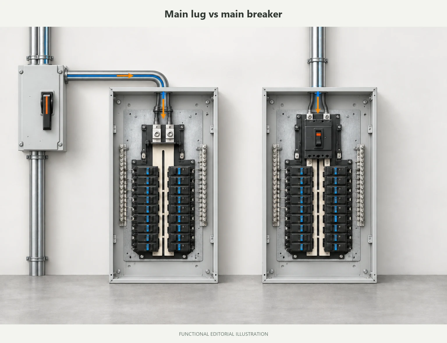
A main lug only (MLO) panel brings the feeder into lugs. The feeder’s overcurrent protection is normally provided upstream. A main breaker panel places a main circuit breaker inside the panel, creating a panel-mounted switching and protection point within the limits of the breaker, panel, and tested combination.
That gives you the basic difference:
- MLO: protection and the required disconnect are mainly handled elsewhere in the distribution arrangement.
- Main breaker: a main device is installed in the panel itself.
Neither label answers the questions that decide whether the panel is suitable. You still need the system role, upstream OCPD, feeder, available fault current, product family, and required disconnecting arrangement.
| Question | Main lug only panel | Main breaker panel |
|---|---|---|
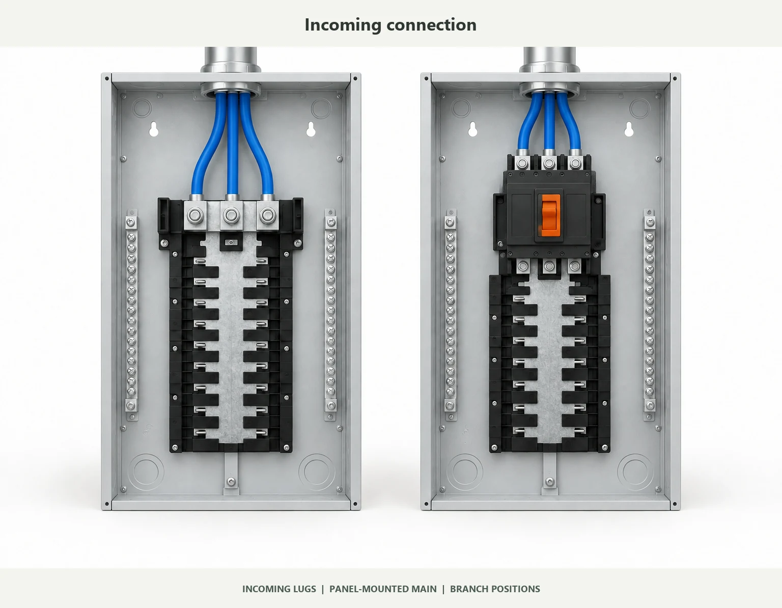
| Where do the incoming conductors land? | Main lugs | The panel-mounted main breaker or its line-side terminals |
| Where is overcurrent protection normally provided? | Upstream | At the panel main breaker, subject to its rating and tested combination |
| When does it usually fit? | A protected feeder already exists and the design does not need a panel-mounted main | The design calls for local operation or a panel-mounted main device |
| What must be checked first? | Upstream OCPD, feeder, bus, lugs, system role, and disconnect location | Breaker frame and rating, bus, fault-current basis, system role, and service requirements |
| Does the name prove compliance? | No | No |
The useful question is not “Which one is safer?” It is: Which configuration matches the system, the installation, the product family, and the responsibility split in the order?
What an MLO panel actually does
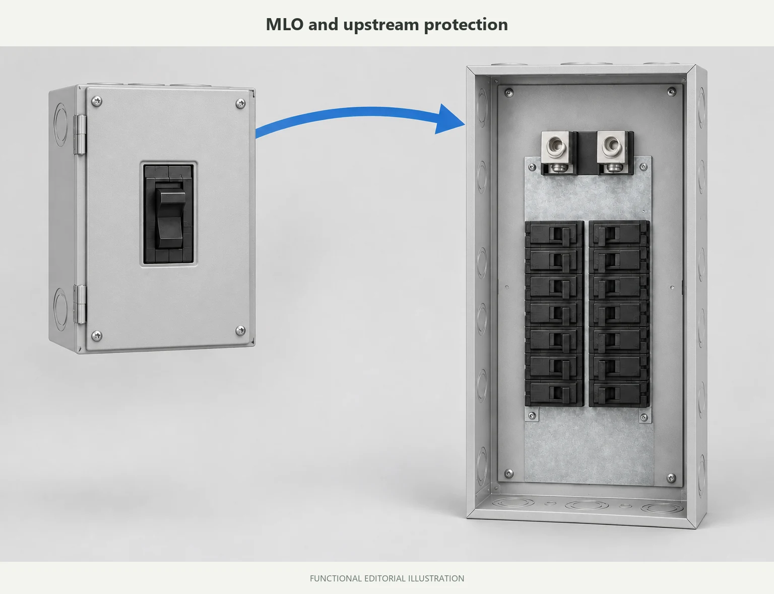
In an MLO arrangement, the feeder lands on the panel lugs instead of a panel-mounted main breaker. That does not mean the feeder has no protection. It means the protective device may be upstream, so the panel cannot be evaluated in isolation.
Before specifying MLO, identify:
- the upstream overcurrent protective device (OCPD);
- feeder conductor size and ampacity;
- bus and terminal ratings;
- whether the panel is service equipment, a feeder panel, or a downstream subpanel;
- the required disconnect and its location;
- available fault current and the panel’s short-circuit rating;
- the required deadfront, grounding, neutral, and enclosure arrangement for the selected product family.
MLO is often a clean fit when a suitable protected feeder is already defined. It is a poor fit when the request is only “200A main lug panel” and nobody has documented what protects that feeder or where the required disconnect will be located. For power distribution enclosure projects, include the feeder routes and approved device layout in the mechanical package.
What a main breaker panel changes
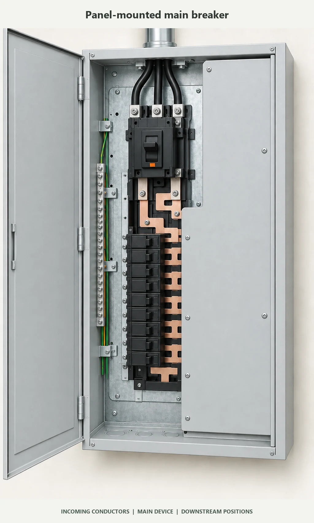
A main breaker puts the main device where the operator or installer can see and use it: inside the panel. That can be useful when the project calls for local switching, a panel-mounted main, or a clear point of operation. To compare the protective function—not just the handle location—review how a circuit breaker works.
It does not make the rest of the design disappear. The breaker rating must match the bus and conductors. The panel must be suitable for the available fault current. The equipment must be approved for the intended service or feeder role. Service-equipment applications can also involve barriers, markings, line-side connections, and installation-specific requirements. Check the actual panel family and manufacturer documentation and UL’s panelboard application guide rather than relying on the phrase “main breaker panel.”
A main breaker is therefore not a shortcut around an incomplete single-line diagram. If the system includes a generator, solar source, battery storage, transfer equipment, or a backfeed arrangement, the power flow and interconnection still need review.
Five differences that affect the selection
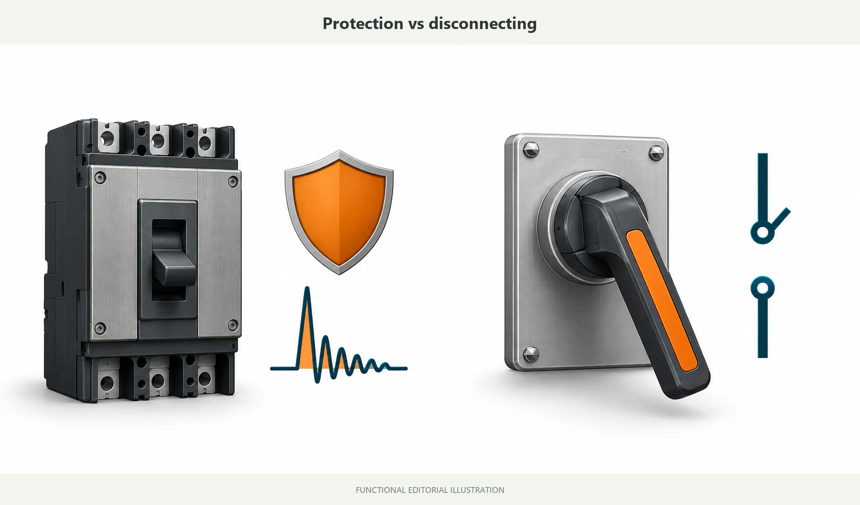
1. Protection and disconnecting are different questions
Overcurrent protection limits the current that conductors and equipment can carry during overloads or faults. A disconnecting means provides a way to isolate equipment or circuits for operation, maintenance, or emergency control, subject to the applicable requirements.
One device or location may serve both functions, but do not assume that it always does. An MLO panel can rely on upstream protection while the required disconnect is located elsewhere. A main breaker can provide a panel-mounted device without automatically resolving every service, building, or upstream disconnect requirement.
Ask two separate questions:
- What protects the feeder and panel?
- Where must the equipment be disconnected?
That simple split prevents many bad comparisons.
2. “Main panel,” “feeder panel,” and “subpanel” describe system roles
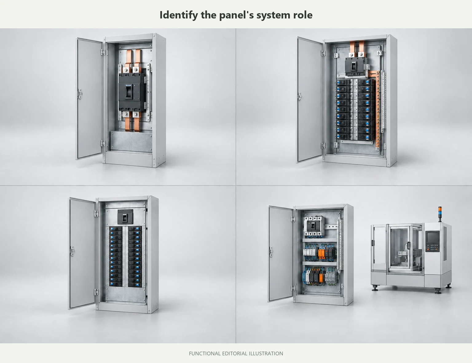
“Main lug” and “main breaker” describe physical configurations. They do not tell you the panel’s role in the system.
A panel may be service equipment, a feeder panel, a subpanel, part of a switchboard, or part of an OEM machine. The answer changes what you need to verify: upstream protection, neutral and grounding arrangement, disconnect location, service construction, markings, and the equipment’s place in the distribution path. If the equipment category is still open, compare switchboard vs panelboard before specifying the main-device arrangement.
This is why “200A panel” is not enough information for a responsible quote. The number gives you one rating. It does not identify the system role or the complete electrical arrangement.
For an OEM machine, industrial automation enclosures provide the mechanical package around the approved layout. The electrical design still determines feeder protection.
3. Feed-through lugs and sub-feed lugs are not the same thing
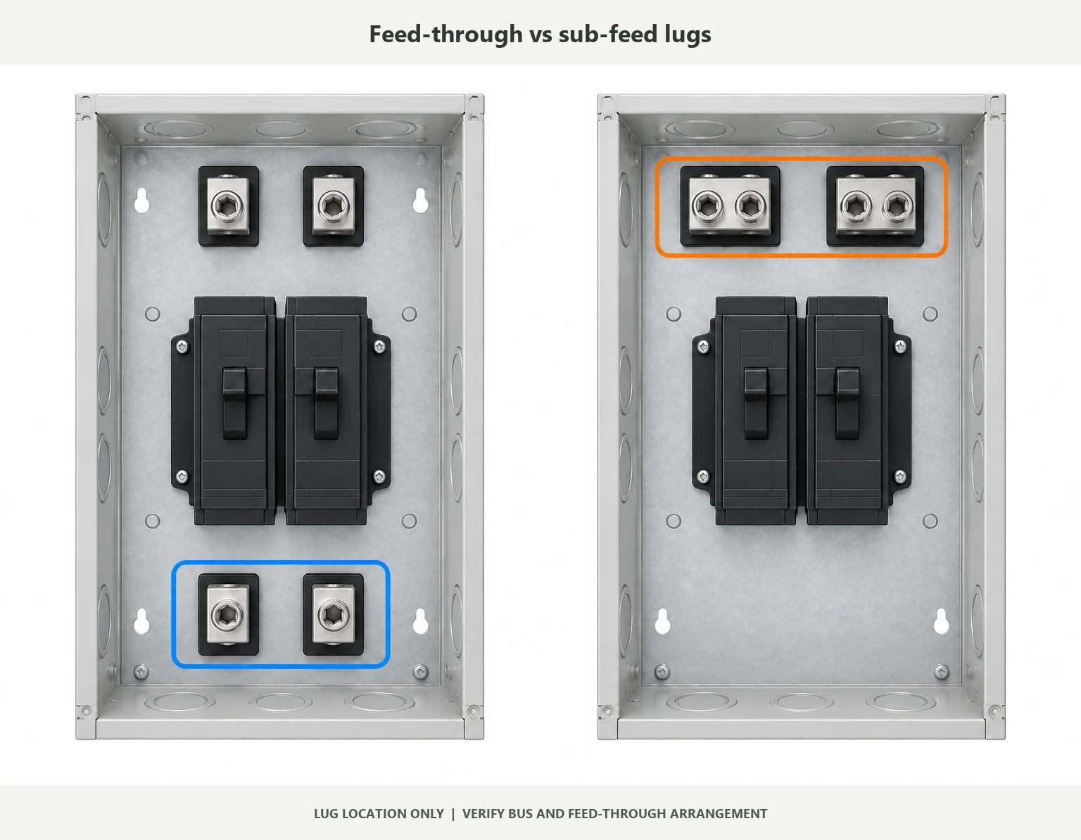
The terms sound similar, but their position and connection inside the panel can differ.
Schneider Electric’s lug guidance describes feed-through lugs as a second set of lugs at the opposite end of the bussing in a specified NQ/NF arrangement. Sub-feed lugs can replace the normal main lugs at the mains end. Sub-feed breakers are another arrangement again. The exact construction depends on the product family and interior.
If one panel will feed another panel or device, ask for the exact accessory and interior documentation. Do not approve an accessory from a similar product photo.
4. Fault-current ratings can change the answer
The main breaker ampere rating is not the complete short-circuit rating of the panel assembly.
Before ordering, confirm:
- available fault current at the installation point;
- the panelboard short-circuit current rating or SCCR basis;
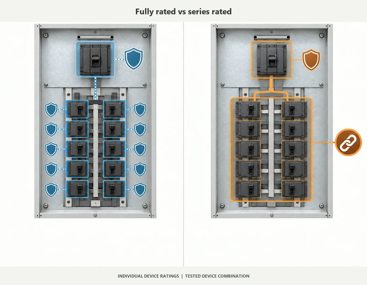
- whether the equipment is fully rated or series rated;
- the approved main-and-branch-device combination if it is series rated;
- required field markings and replacement-device restrictions.
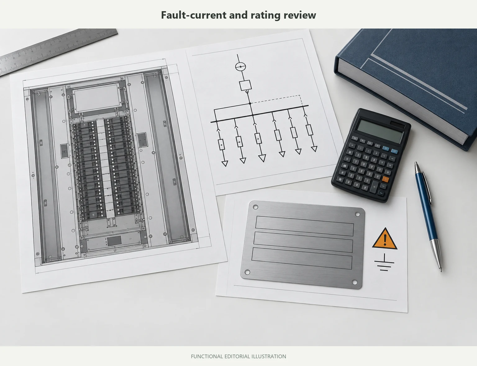
In a fully rated system, the protective devices are evaluated for the required fault-current level. In a series-rated system, the main and branch devices are evaluated as a specific combination. Replacing one device with an unapproved alternative can break that intended combination. UL’s short-circuit rating guidance also emphasizes field marking and identified replacement components.
If the available fault current is missing from the project information, the right status is needs engineering confirmation. “Use the higher ampere option” is not a fault-current analysis.
5. Conversion is a product-family decision, not a visual-fit decision
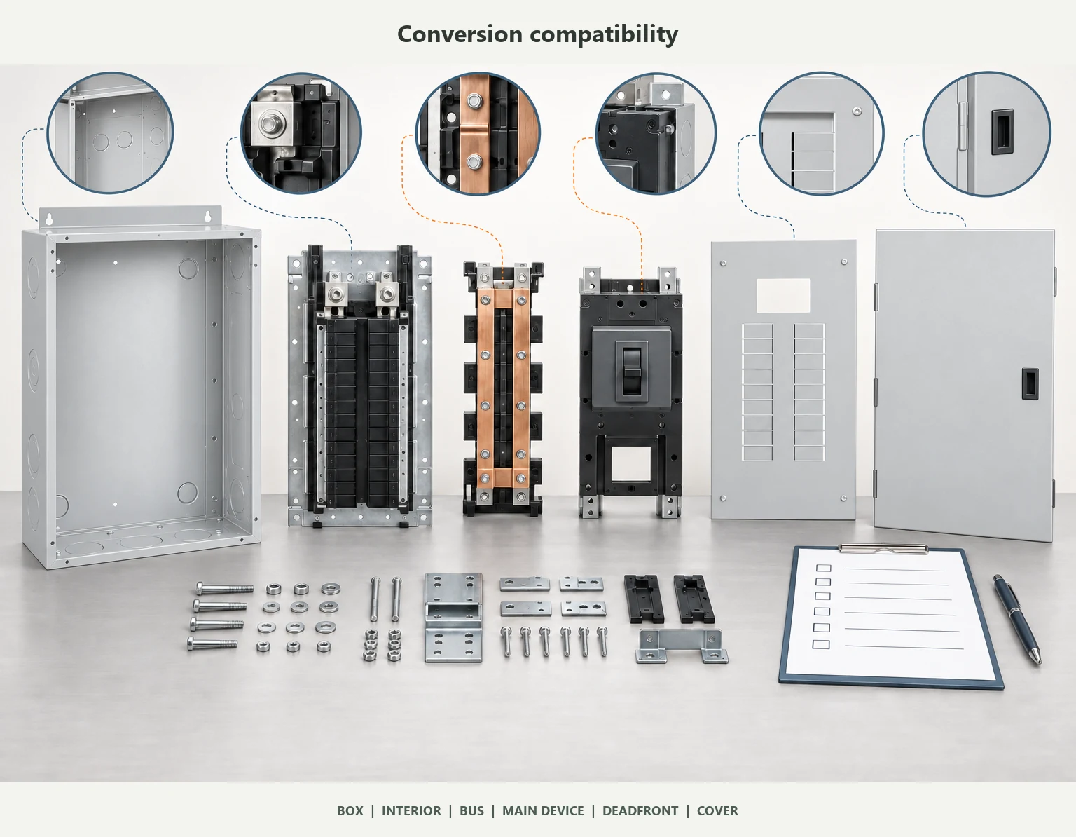
Some load centers and panelboards are convertible. Others are not. Even within one brand, different series can use different boxes, interiors, breaker frames, deadfronts, barriers, and kits.
Schneider documents a specific NQ conversion using named kits and a specified box arrangement. Schneider’s QO and Homeline conversion guidance limits a main-breaker conversion kit to identified QO and Homeline series and states that older series are not convertible. Leviton’s conversion-kit instructions also identify a particular kit and enclosure family.
Before approving a conversion, match all of these items:
- manufacturer and exact series;
- catalog number;
- box or enclosure;
- interior and bus;
- breaker frame;
- conversion-kit number;
- deadfront and cover;
- ratings and markings;
- manufacturer instructions.
A generic catalog description or a photograph of a similar panel is not enough.
Keep the electrical conversion decision separate from standard vs custom enclosure fabrication. A change to the box does not establish breaker-kit compatibility.
When should you choose a main lug panel?
MLO is a reasonable choice when the following conditions are already clear:
- The panel’s system role is defined.
- A suitable upstream OCPD is identified.
- The feeder, bus, lugs, and fault-current basis are compatible.
- The required disconnect is provided in the correct location.
- The product family is approved for the intended arrangement.
- The project does not require a panel-mounted main for operation or specification reasons.
Typical contexts include a downstream distribution panel, an expansion panel fed from an already protected feeder, or an OEM arrangement where upstream protection and system boundaries are documented elsewhere.
MLO is not automatically unsafe. It is simply dependent on the protection and disconnecting arrangement around it.
When does a main breaker panel make more sense?
A main breaker panel may be the better fit when:
- the design requires a panel-mounted main device;
- local operation or isolation matters at the panel location;
- the project specification names a main breaker arrangement;
- the panel’s role and service requirements support that configuration;
- the selected breaker, bus, enclosure, and fault-current ratings are documented as a tested combination.
The visible breaker can make operation easier to understand on site. That is a practical benefit. It is not a substitute for confirming the electrical design.
What to confirm before ordering
If the request on your desk says only “Please quote a 200A main lug panel,” the quote is not ready. Use the fields below to turn a label into a buildable, reviewable scope. If the enclosure specification is still open, use how to choose an electrical enclosure alongside the electrical documents.
| RFQ field | Confirm or provide | Why it matters |
|---|---|---|
| Scope boundary | Empty enclosure, panelboard interior, mechanical assembly, complete electrical assembly, or another scope | Clarifies enclosure versus complete control-panel scope so the buyer and supplier price the same responsibilities |
| System role | Service equipment, feeder panel, subpanel, OEM equipment, or other role | Determines which technical and documentation checks apply |
| Electrical data | Voltage, phase, wires, frequency, grounding system, and poles | Prevents a physically similar but electrically wrong selection |
| Load and feeder | Calculated load, upstream OCPD, feeder conductors, and planned future load | Ampere value alone does not establish suitability |
| Fault current | Available fault current and required SCCR/AIC basis | Needed to evaluate the panel and protective-device combination |
| Main-device choice | MLO, main breaker, fused disconnect, or another specified arrangement | Keeps the quote aligned with the design intent |
| Product identity | Brand, series, catalog number, interior, box, cover, and deadfront | Prevents unsupported conversion and interchange assumptions |
| Accessories | Feed-through lugs, sub-feed lugs, sub-feed breaker, interlock, barriers, or extension kits | Accessories can change the interior and documentation requirements |
| Conductors and terminals | Copper or aluminum, wire size, conductor count, terminal range, temperature rating, and torque | Avoids terminal and field-connection surprises |
| Installation environment | Indoor or outdoor, mounting method, corrosion exposure, washdown, space, and cable-entry direction | Drives enclosure construction and layout; include outdoor enclosure design requirements where applicable |
| Multi-source equipment | Generator, solar, battery storage, transfer equipment, or backfeed | Adds system-level review beyond the MLO/main-breaker label |
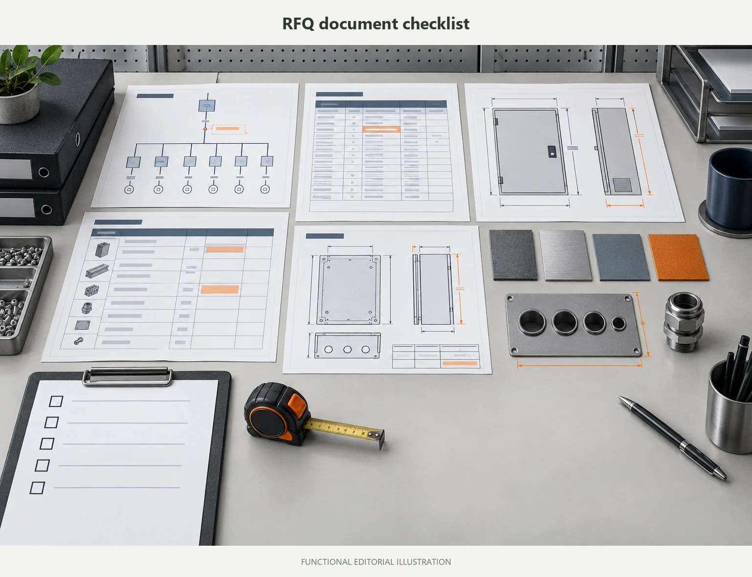
| Documents | Single-line diagram, panel schedule, cutout and cable-entry drawings, approved BOM, drawing revision, and inspection requirements | Makes the quotation reviewable and reduces revision risk |
Include a dimensioned layout for the electrical enclosure sizing review, showing the mounting area, cable routes, entry positions, and door clearance.
What FN Enclosure can support
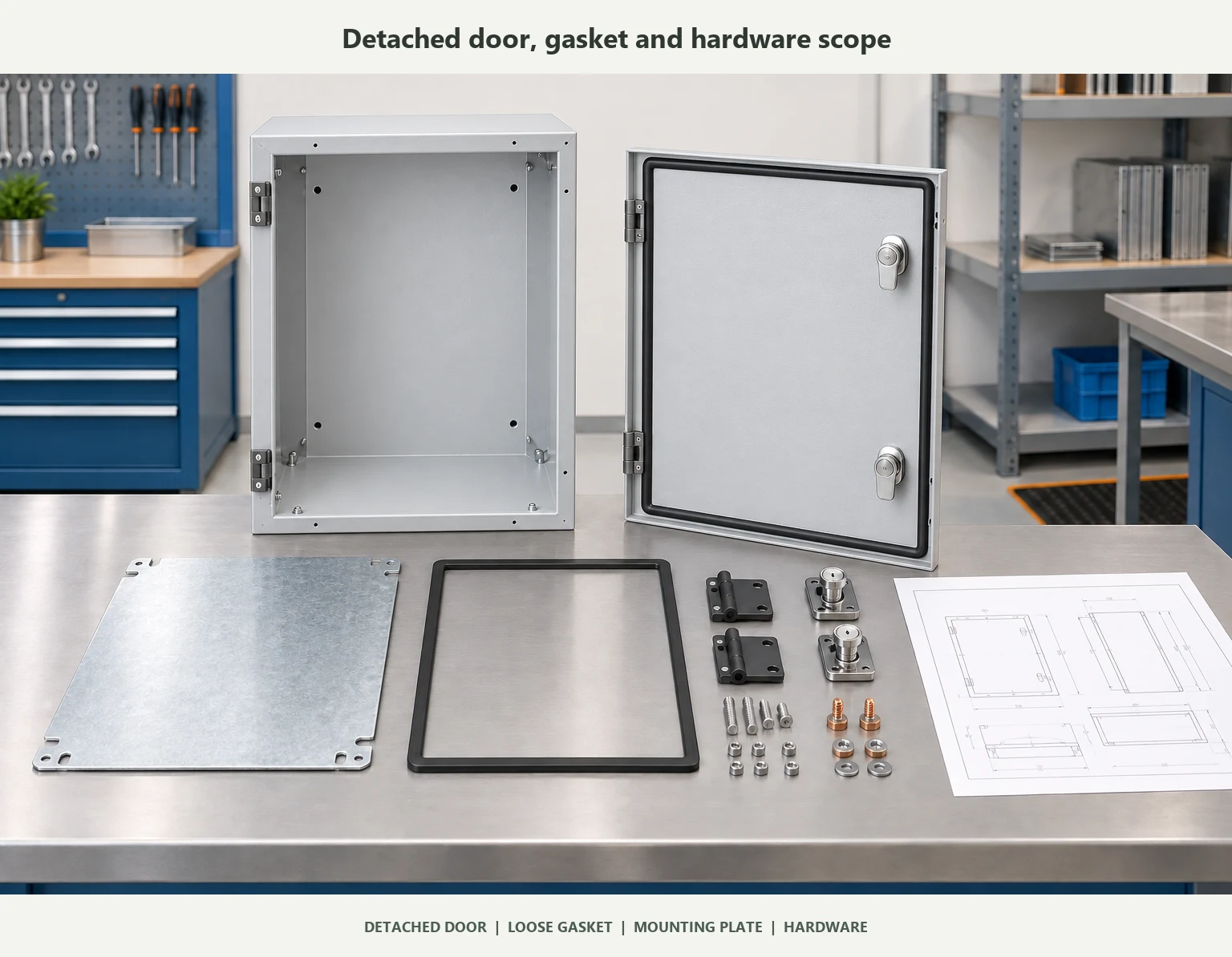
If the electrical design is already defined and you need the enclosure or electrical package around it, start with a drawing-based scope rather than a product label. FN Enclosure can review a drawing-based package for custom electrical enclosures, covering the body, door, mounting plate, gasket, hinges, locks or latches, grounding studs, and drawing-defined cutouts. DIN rails, gland plates, customer-supplied parts handling, and electrical fitting can be considered when they are quoted and approved as part of the project scope.
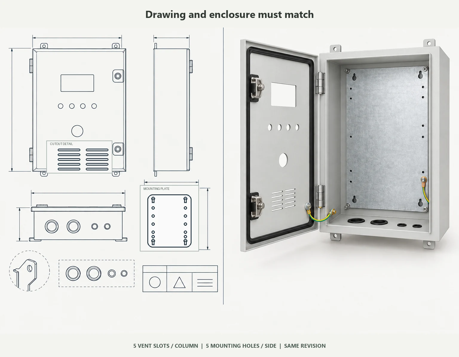
For the buyer, the practical benefit is control: component locations, mounting points, cutouts, cable-entry direction, material, finish, and drawing revision can be tied to one approved package. FN’s project workflow records DFM and supply-boundary review, drawing approval, first-article approval when required, change control, and final inspection documentation.
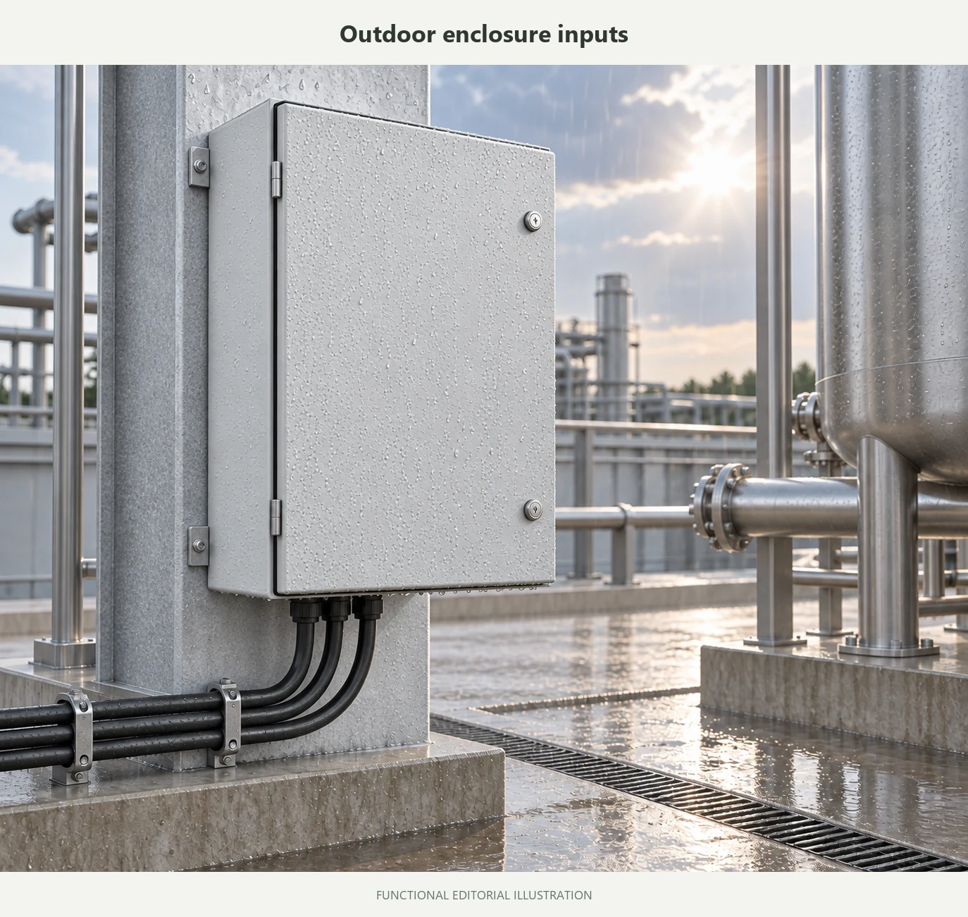
For outdoor equipment, confirm the actual environmental requirement before considering an IP65 electrical enclosure or IP66 electrical enclosure. An enclosure rating does not, by itself, certify the complete electrical assembly.
Frequently asked questions
Is a main lug panel the same as a subpanel?
No. “Main lug” describes the incoming connection configuration. “Subpanel” describes the panel’s downstream role. An MLO panel is often used as a subpanel, but the terms are not interchangeable.
Does a subpanel always need a main breaker?
Not necessarily. Confirm the upstream OCPD, feeder, panel rating, building or equipment location, required disconnect, and applicable local requirements. The word “subpanel” alone does not tell you whether a panel-mounted main breaker is required.
Can you convert a main lug panel to a main breaker panel?
Sometimes, but only with documented compatibility. Use the product-family conversion checks to confirm the exact manufacturer, series, box, interior, breaker frame, conversion kit, deadfront, cover, ratings, and instructions.
Is a main lug panel unsafe without a main breaker?
Not automatically. The answer depends on where protection is provided, how the panel is used, where the required disconnect is located, and whether the complete arrangement is properly rated and documented.
Are feed-through lugs protected by the main breaker?
It depends on the product arrangement. Schneider’s NQ/NF feed-through lug guidance describes feed-through lugs connected to the bussing and says loads connected to them are protected by the panel’s main breaker in the specified main-breaker arrangement. Do not apply that statement to every brand or interior; verify the exact product documentation.
What should I send with an RFQ?
Send the single-line diagram, panel schedule, system role, electrical ratings, available fault current, product series or approved device list, enclosure dimensions, cutout and cable-entry drawings, environment, material and finish, required accessories, drawing revision, and a clear statement of whether the supplier is quoting an enclosure, mechanical assembly, or complete electrical package.
Final takeaway
Do not choose a main lug or main breaker panel because the name sounds safer, simpler, or cheaper.
First identify the panel’s role. Then separate protection from disconnecting. Confirm fault-current ratings, device combinations, product-family compatibility, accessories, enclosure conditions, and the supply boundary. Only then should the panel or enclosure be quoted.
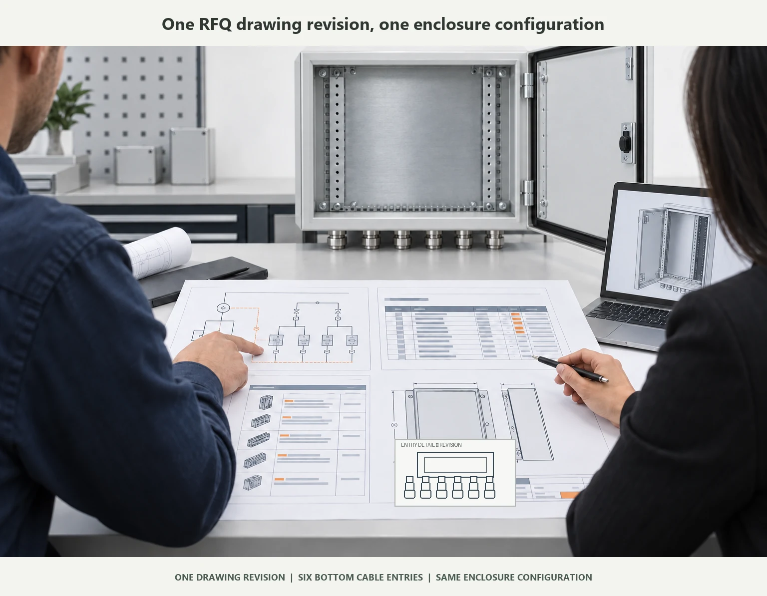
For an enclosure OEM, “quote a 200A main lug panel” is not a complete requirement. A usable RFQ includes the drawings, ratings, interfaces, environment, accessories, revision, and responsibility boundaries that define the build. If you already have those documents, send your enclosure drawings for review.
Sources and manufacturer documentation
- Schneider Electric: Feed-through and sub-feed lug definitions
- Schneider Electric: Sub-feed lugs, through-feed lugs, and sub-feed breakers
- Schneider Electric: QO and Homeline main-breaker conversion guidance
- Schneider Electric: NQ conversion and box compatibility
- Schneider Electric: Fully rated and series-rated panelboards
- UL Solutions: Panelboard and switchboard short-circuit current ratings
- Leviton: Main-breaker conversion-kit instructions
- Schneider Electric: UL 67 service-entrance construction guidance
- UL Solutions: Panelboard application guide