FIBERGLASS ENCLOSURE BODIES
Fiberglass Enclosures for Metering and Distribution
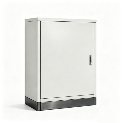
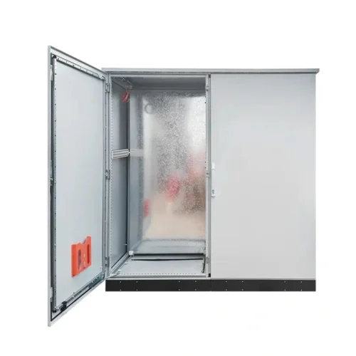
Select the body around the equipment and installation. FN supplies molded fiberglass enclosure bodies for distribution, cable-branch and metering applications. Dimensions, doors, compartments and mounting interfaces are selected by model.
Choose the body layout to suit the equipment and required access.
SMC or DMC compound is identified for the selected model.
Check the overall envelope and usable internal space together.
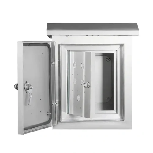
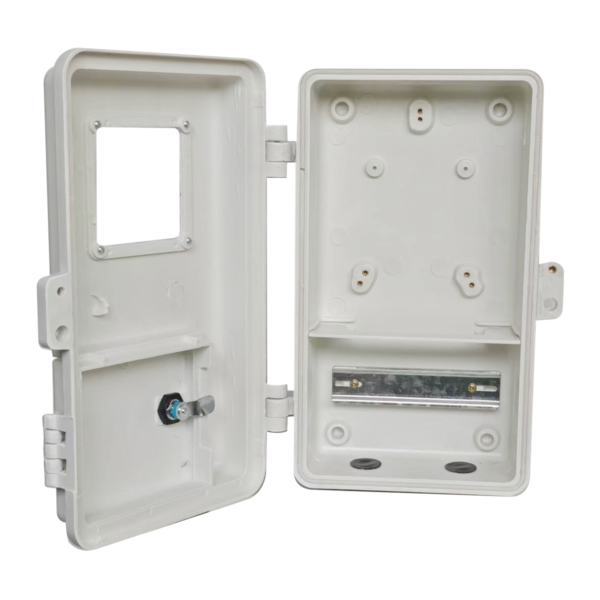
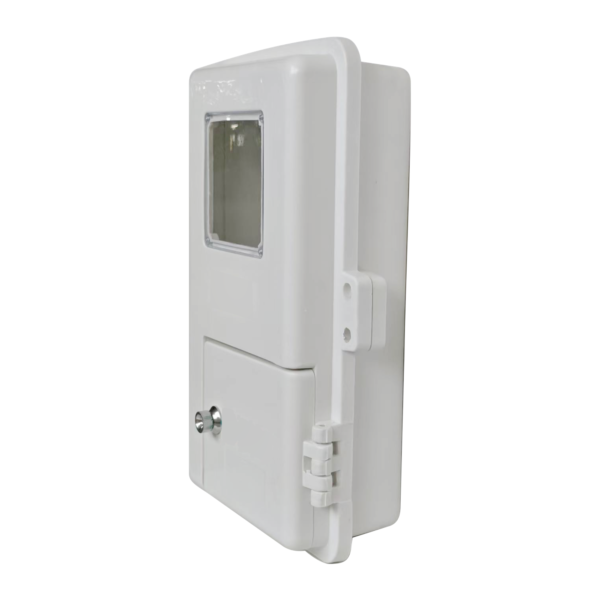
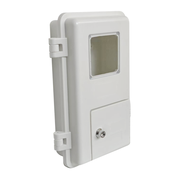
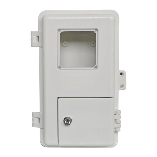
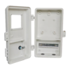
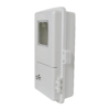
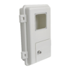
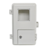
Meter-box forms use application-specific viewing and compartment arrangements.
Use the selected drawing to define the hole pattern, support and entry locations.
Electrical devices, wiring and assembly are separate quotation items.
Best fit
- Distribution and cable-branch projects needing a housing for specified internal equipment.
- Metering projects with a defined viewing-window and access arrangement.
- OEM projects sourcing the enclosure body separately from the electrical components.
Supply scope
This page covers enclosure bodies. State the required door, window, lock, mounting parts and other mechanical items in the RFQ.
Meters, breakers, switches, terminals, busbars, wiring and complete electrical assemblies are included only when separately agreed in the quotation.
Start with the model drawing. Check usable internal space, door access, mounting and cable-entry positions before selecting the body.
DESIGN & CUSTOM OPTIONS
Select the Enclosure Form and Installation Interfaces
Match the molded body to the equipment layout, access and mounting arrangement. The selected model drawing and agreed parts list define the supplied configuration.
Details to define for the selected model
| Selection item | Body configuration | Project input |
|---|---|---|
| Enclosure form | Distribution-box, cable-branch or meter-box body. | Equipment type, layout and required compartments. |
| Dimensions | Overall height, width and depth from the selected drawing. | Usable internal space, equipment clearance and installation limits. |
| Door and access | Model-specific door, viewing-window and compartment arrangement. | Opening clearance, access direction and visibility requirements. |
| Mounting | Mounting points and supporting hardware for the chosen body. | Wall or pole arrangement, hole pattern, fasteners and support. |
| Cable entries | Existing openings and any proposed additional cut-outs. | Entry positions, cable or gland dimensions and required clearances. |
| Material and appearance | Glass-fiber-reinforced compound and finish by model. | Material documentation, color, labels and marking requirements. |
Example distribution-body dimensions
Each example below lists overall body dimensions (H × W × D), followed by the installation dimensions shown. Availability and supplied parts are set out in the selected model drawing and quotation.
| Overall size — H × W × D | Installation dimensions shown |
|---|---|
| 300 × 250 × 150 mm | 240 × 165 mm |
| 400 × 300 × 180 mm | 335 × 222 mm |
| 500 × 400 × 200 mm | 438 × 322 mm |
Installation dimensions are separate from body size. Check actual hole centers and the supporting structure against the selected model drawing. The examples above do not define a continuous size range.
Meter-box layouts
Meter-box bodies use application-specific viewing windows and access arrangements. Specify the meter type, number of positions, compartment layout and required clearance when choosing the body.
Requested changes
Send a marked-up drawing for additional openings or a different interface. Non-standard dimensions, window changes and cut-outs require a feasibility review for the chosen model and molding method. Accepted changes are recorded in the drawing and quotation.
ENGINEERING & QUALITY
Define the Model Before Order Release
Use the selected body drawing and parts list to align the enclosure with the installation. Record the interfaces, supply scope and acceptance requirements before approving the order.
Six points for model review
- Body and clearanceIdentify the body form, overall dimensions, equipment envelope and usable mounting area.
- Mounting interfaceCheck hole locations, support, fasteners and access for installation.
- Door and viewing areaDefine door clearance, window position, compartment separation and access to equipment.
- Cable entriesMark entry positions, fitting dimensions and any requested modifications.
- Supply boundaryList the enclosure parts, hardware and any separately agreed components.
- Acceptance requirementsSpecify dimensional checks, appearance, required documents, labels and packing.
Material and environmental requirements
The product family uses molded glass-fiber-reinforced plastic, with the SMC or DMC compound identified for the selected model. Include the installation environment and required material documentation in the RFQ.
Dimensions and interfaces
Identify the dimensions and hole positions that affect equipment fit and installation. Agree any required tolerances and checking method.
Door and hardware
Define access, lock operation, window requirements and the mechanical parts included in the order.
Environmental exposure
State rain, sunlight, temperature, humidity and chemical exposure. Review the body, seals, openings and entry fittings as a configuration.
Required evidence
List any required IP rating, NEMA Type, flame classification or UV/weathering evidence. Applicable reports must identify the relevant model and configuration.
Documents and packing inputs
| Area | Define in the enquiry | Order agreement |
|---|---|---|
| Drawings and parts | Model, dimensioned drawing and included mechanical parts. | Selected drawing revision and supplied configuration. |
| Material and testing | Required material declarations, reports or project-specific checks. | Available evidence, applicable scope and any additional work. |
| Inspection records | Critical dimensions, functional checks and reporting format. | Agreed inspection scope and acceptance criteria. |
| Labels and packing | Quantity, destination, handling, labeling and packing requirements. | Packing method and identification of included loose parts. |
PROJECT QUOTATION
What to Send for a Fiberglass Enclosure Quote
Send the required body form, installation details and included parts. A marked-up sketch and equipment photos can help identify the model when a complete drawing is not yet available.
Supply boundary
| Area | Details to agree | Scope boundary |
|---|---|---|
| Enclosure body | Selected body, door, window, lock and other model-specific parts. | The quotation identifies the actual supplied configuration. |
| Mounting and entries | Mounting parts, hole pattern, cable entries and accepted modifications. | Additional parts and changes are included only when agreed. |
| Electrical equipment | Any separately requested meters, breakers, switches, terminals or wiring. | Electrical devices and internal assembly are outside the enclosure-body scope unless separately quoted. |
| Project evidence | Required documents, checks and acceptance criteria. | An enclosure-body order does not establish approval of the completed electrical system. |
Eight details for quotation
- Required body form or a model reference and photo.
- Overall height, width and depth, plus an equipment sketch.
- Door, viewing-window and compartment requirements.
- Mounting arrangement, hole positions and supporting hardware.
- Cable-entry positions and requested cut-outs.
- Included mechanical parts and any separate electrical scope.
- Installation environment and required ratings or documents.
- Quantity, destination, packing and target schedule.
Send all three dimensions together. Add the equipment layout and mounting arrangement so the body size, access and installation interface can be reviewed.
Fiberglass Electrical Enclosure FAQs
Are meters or breakers included?
This product page covers enclosure bodies. Meters, breakers, switches, wiring and other internal equipment are separate scope items and must be listed in the quotation if required.
Which fiberglass material is used?
The range is based on molded glass-fiber-reinforced plastic. The selected model determines whether SMC or DMC compound applies. State the material documentation needed for your project.
Can the body be mounted on a wall or pole?
Wall and pole installations depend on the selected model and supporting hardware. Send the mounting arrangement, loads and hole-pattern requirements so the interface can be reviewed.
Can I request another size or cable-entry layout?
Send the required dimensions and a marked-up entry layout. Changes are subject to the model and production-method review, with the accepted scope recorded on the drawing and quotation.
Are these enclosures suitable for outdoor use?
Suitability depends on the model, seals, openings and exposure conditions. Include rain, sunlight, temperature and chemical exposure in your enquiry, together with any required IP/NEMA or weathering evidence.
What dimensions are available?
The example table lists individual distribution-body configurations. Send the required overall dimensions and equipment layout to identify a suitable model and current supply configuration.