
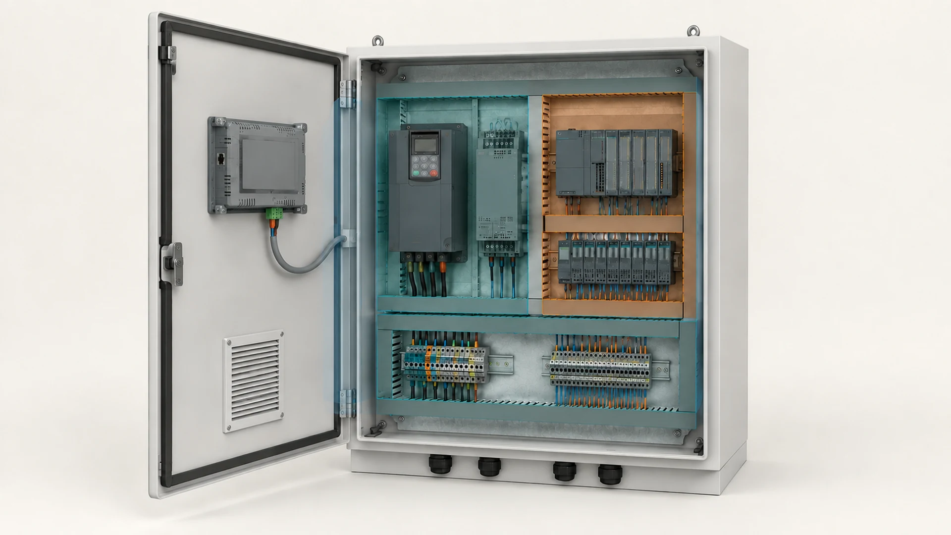

PLC control panel design starts with what you need the machine to do. Build the I/O list, work through the electrical schematics, and lay out the equipment with room for wiring, cooling and maintenance. Before you release the cabinet drawings, check that those decisions agree with one another.
We’ll use a small pump skid as a worked example. Follow a signal from the field device to the PLC, check the space behind the HMI, then pull together the information you need for an enclosure quote. If your drawings are still taking shape, you can bring them to FN for an initial review.
1. Start with how you want the machine to run
What should happen when an operator presses Start? What should happen after a fault or a lost connection?
Write down those answers alongside the incoming supply, connected loads and operating conditions. They give your designer something concrete to work from when selecting equipment and preparing the drawings.
A useful sequence is:
Operating requirements → I/O schedule → schematics and terminal plan → physical layout → fabrication drawings and tests.
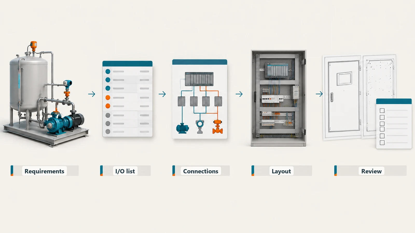
You’ll probably work on several of these at once. Keep the open decisions visible. If you’re still choosing the HMI, mark its model and door cutout as provisional so nobody treats the opening as ready for fabrication.
Need a refresher on what each device does? The electrical control panel components guide covers that separately.
2. Work from an I/O list you can trace
For this illustrative example, let’s use a transfer-pump skid with a PLC, a VFD-controlled pump and a door-mounted HMI. The drive uses hardwired commands and feedback. The HMI connects over Ethernet, and a level transmitter monitors the tank.
Here are the process signals we’ll follow. Safety functions, auxiliary equipment and spare channels need their own entries in the full project schedule.
| Example signal | PLC interface | Proposed termination group | What you need to confirm |
|---|---|---|---|
| LT-101 tank level | Analog input, assumed 4-20 mA | XT-AI | Transmitter wiring, loop supply and input compatibility |
| VFD-101 running feedback | Digital input | XT-DI | Drive output type, voltage and input common |
| VFD-101 fault feedback | Digital input | XT-DI | Contact behavior and the meaning of a healthy/fault state |
| VFD-101 run request | Digital output | XT-DO | Drive input requirements and any interposing device |
| VFD-101 speed reference | Analog output, assumed 4-20 mA | XT-AO | Drive input configuration and output compatibility |
| HMI-101 operator link | Ethernet connection | Network connector | Protocol, addressing and connector access |
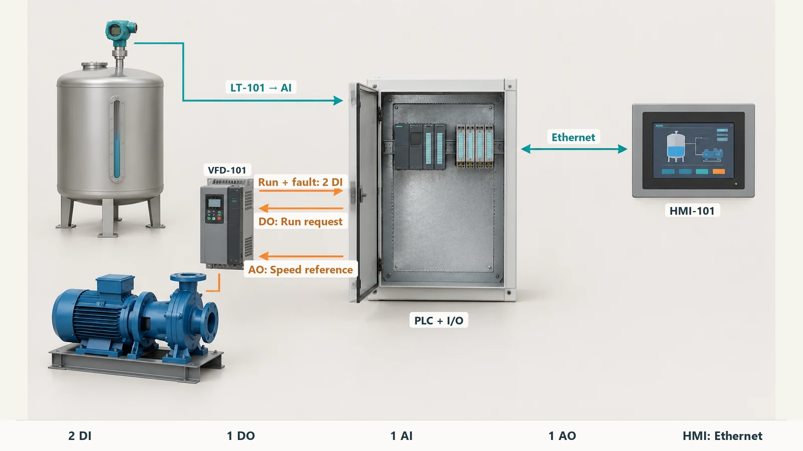
For these signals, you need two digital inputs, one digital output, one analog input and one analog output, plus the HMI connection. The XT labels help organize the discussion. Your final drawings will assign the terminal numbers and any direct internal connections.
Check both ends of each signal. For DC discrete inputs, that includes the sinking/sourcing arrangement in the device and module manuals.
Put those connections on the layout
Now place the PLC and I/O, terminal groups and connecting routes. Add the drive, control-power distribution and any network hardware. Use the actual device drawings to check the space each item needs.
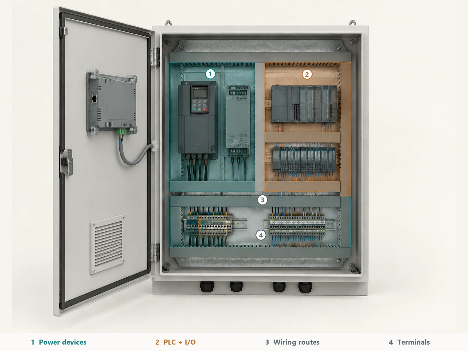
Take LT-101. Where does its cable enter? Follow it to the termination group, the analog module and the configured channel. Then look at the drive wiring nearby. If you move the entry or the terminal group, update the route on the drawing too.
Do the same for VFD-101, including its cable connections and required clearance. A drive that fits on the plate still needs room around it to connect and service. Simcona’s layout guidance covers these practical questions around wireways, field wiring, access and expansion.
3. PLC control panel layout: leave room to wire and service it
Put the wireways and terminals on the drawing while you’re placing the devices. Leave access to terminal screws, labels and connectors, and check how someone would remove a failed module. Use the device manuals for installation clearances.
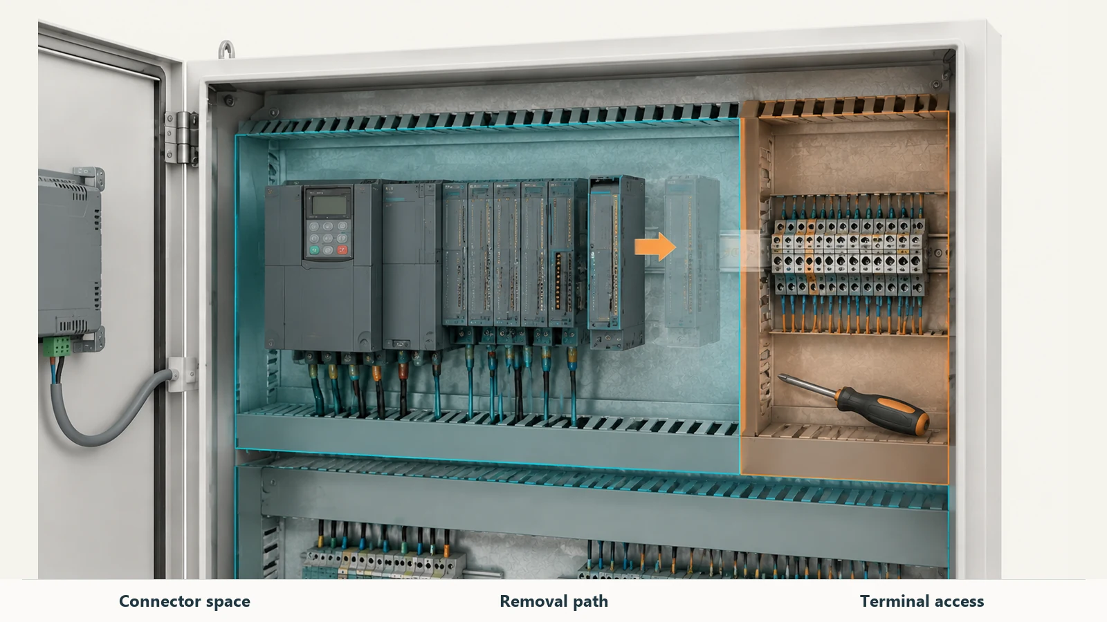
Think through expansion the same way. If you expect another analog module later, make room for its terminals and cable route as well as the module itself. Include its power demand in the review.
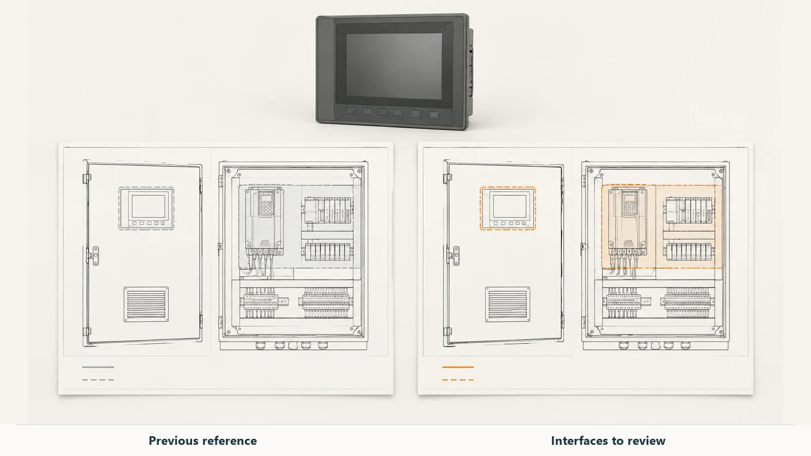
Look behind the HMI before approving the door
Suppose the HMI fits the front opening, but its rear connector occupies the same space as an I/O module. You still have options while the drawings are open: review the device positions, the door arrangement or the cabinet depth.
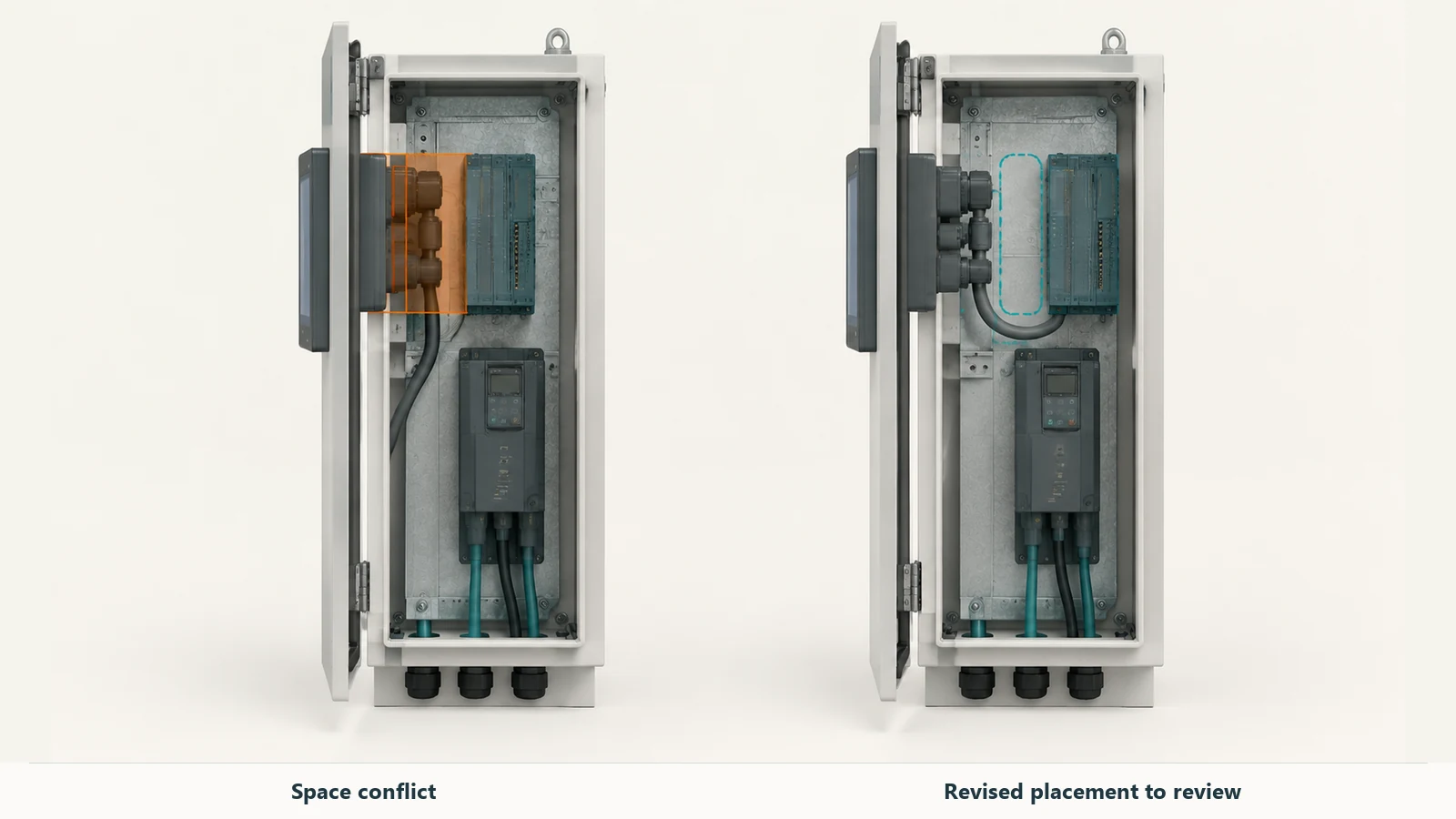
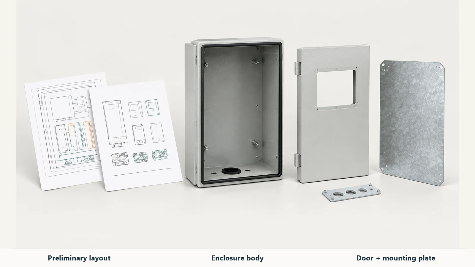
At FN, we can review these mechanical interfaces from your component drawings or preliminary layout. We make the cabinet body, door and mounting plate to the approved drawings, including specified cutouts and mounting features. That gives you a way to plan the opening and the equipment behind it together, while the layout can still be changed.
Send the exact HMI drawing, rear projection and device weight. For the wider space review, use the electrical enclosure sizing guide.
4. PLC control panel wiring: make each connection easy to follow
Show the power and sensitive-signal routes on the layout. Switching equipment such as VFDs can introduce noise into control circuits, so cable separation, shielding and grounding need attention during design.
In our pump-skid example, trace the LT-101 analog route separately from the drive power and motor routes. Use the equipment manuals and your system grounding design to decide how its shield will terminate.
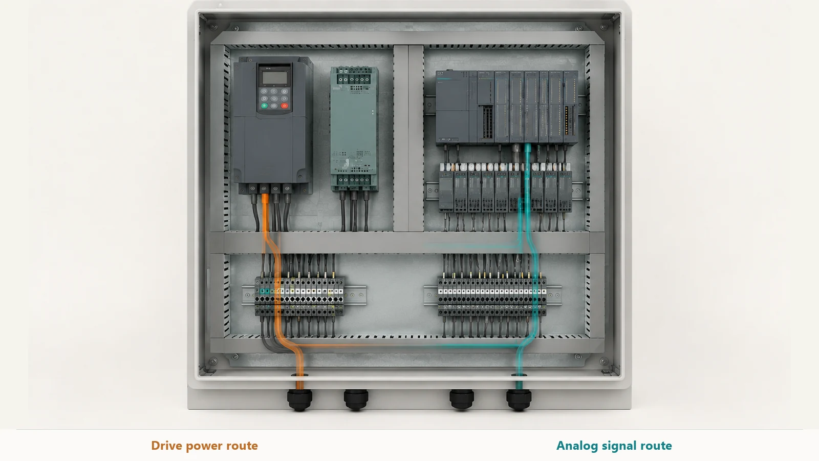
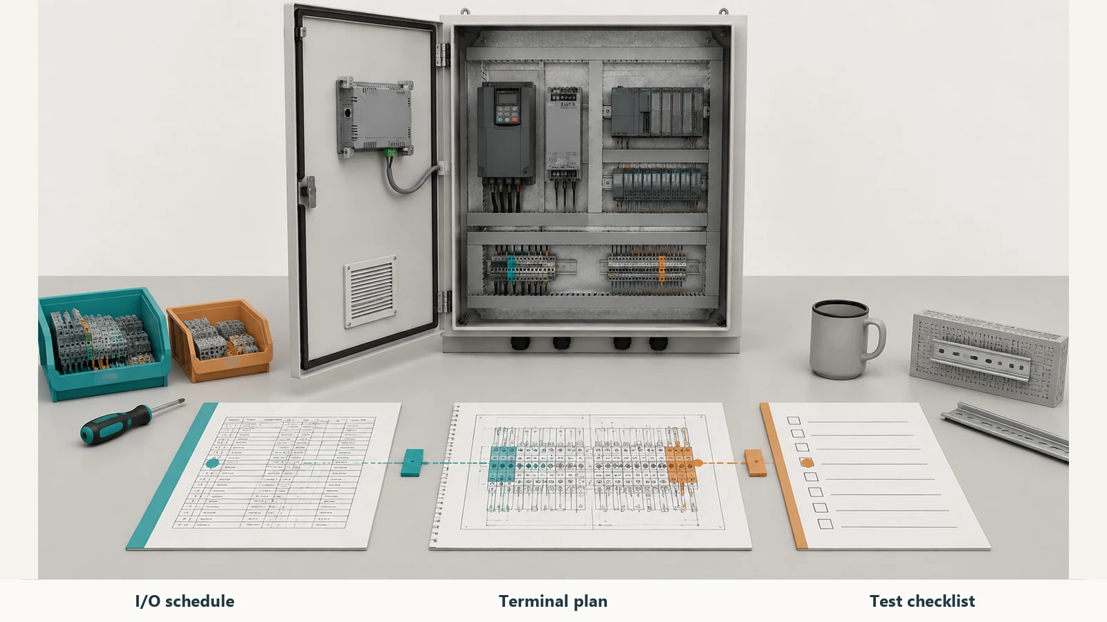
Keep the same signal tag in the I/O schedule, schematic, terminal plan and software. Pick one field device and follow it through all four. If the references disagree, you’ve found a drawing or configuration to resolve before testing.
Give your electrical designer the inputs they need
Alongside the layout, have the responsible designer or panel builder confirm:
- The incoming supply, connected loads and isolation arrangement.
- Overcurrent protection, conductor selection and terminal ratings.
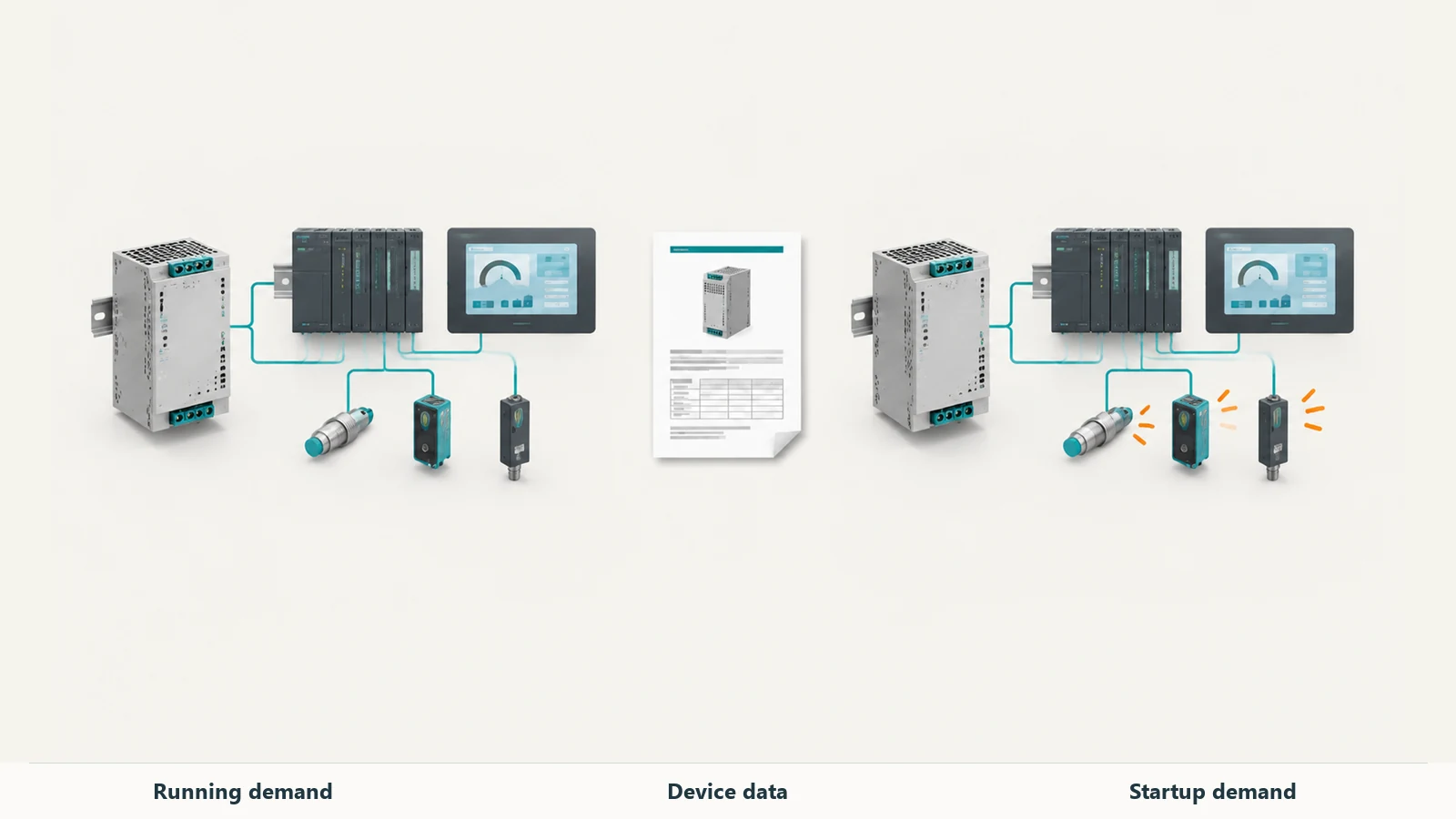
- Control-power demand during normal operation and startup. Eaton’s sizing guidance checks both nominal demand and inrush.
- Grounding, bonding, installation requirements and the project’s approval route.
For a US machinery project, establish the applicable short-circuit current rating (SCCR) requirements and obtain the available fault-current information at the supply point. UL explains why those values need to be checked together. Your designer will need the project’s applicable code edition and evaluation method, along with the selected circuit components.
The I/O count is one input to this work. Use the actual connected equipment to size the power supply and select protection and conductors.
5. Bring cooling and cable entry into the drawing review
Collect the equipment heat-loss data and expected ambient conditions before choosing the cooling approach. A ventilation fan exchanges air with its surroundings, so it cannot cool the enclosure below the incoming air temperature. Contamination and allowable internal temperature also affect the choice.
Once you’ve selected the cooling equipment, add its drawing to the layout. The enclosure cooling guide can help you compare the options.
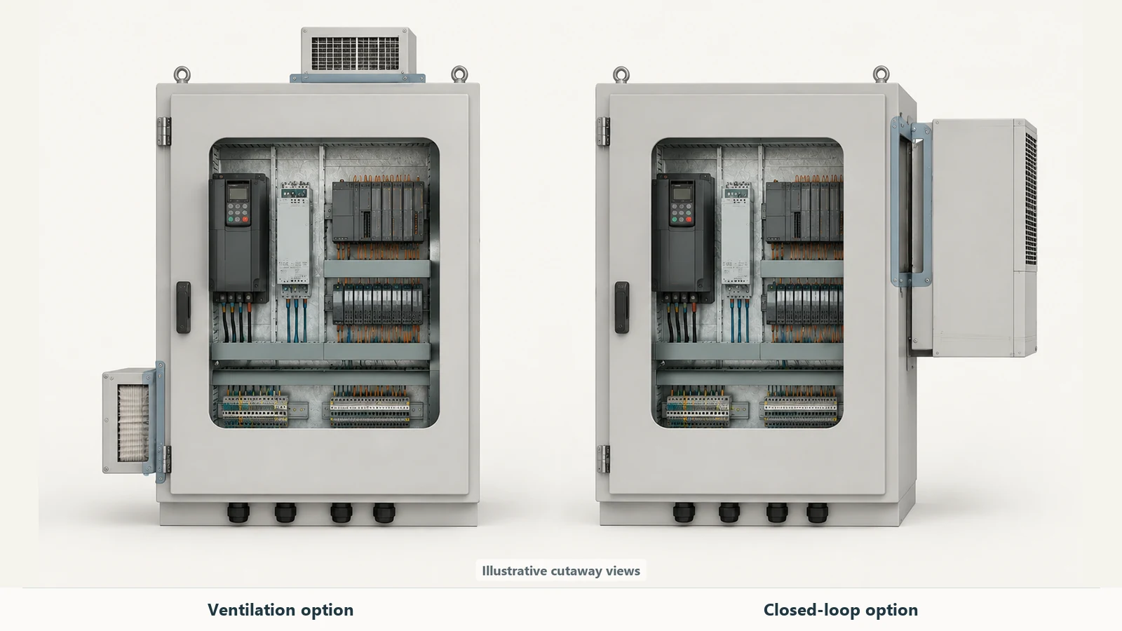
For the pump-skid example, keep this short list with your drawings:
| Interface | Information to bring to the review | Drawing affected |
|---|---|---|
| VFD and other heat-producing equipment | Device loss data, ambient conditions and cooling concept | Cooling openings and nearby equipment layout |
| HMI-101 | Exact cutout, fixing pattern, rear projection and connector drawing | Door fabrication drawing |
| LT-101 and other field cables | Cable schedule, entry direction, terminations and entry hardware | Gland plate and terminal arrangement |
| PLC and I/O assembly | Final modules, dimensions, connectors and planned expansion | Mounting-plate layout |
| Installation and handling | Available access, mounting arrangement and delivery constraints | External arrangement and handling provisions |
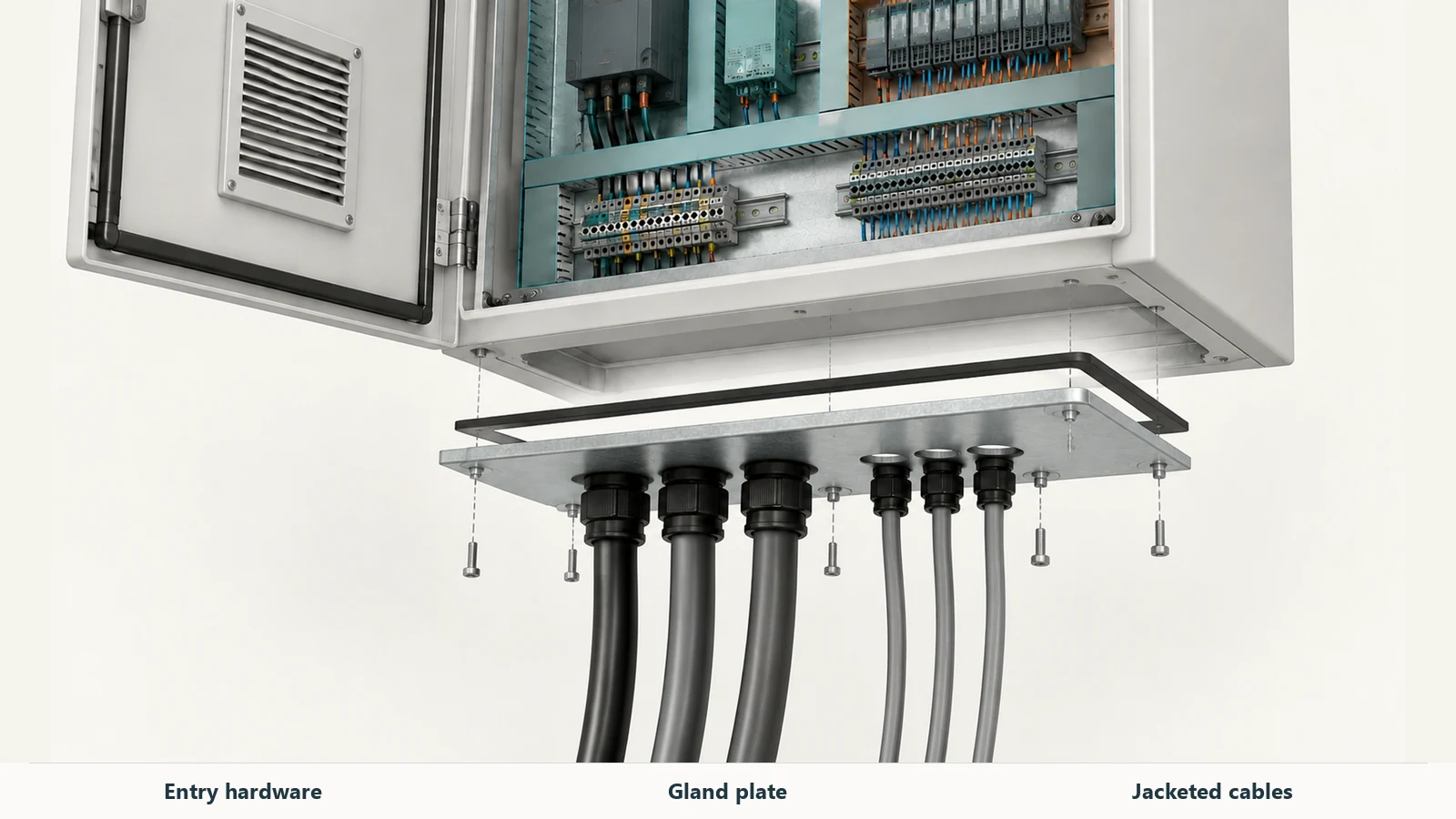
If a component changes, check which drawings change with it. A different HMI may affect the door and the plate layout; a different cooling unit may move an opening. Record the revised drawing numbers and approvals so the builder has a clear manufacturing reference.
6. Check the drawings against what you’ll test
Bring the BOM, layout, schematics, grounding details, I/O terminations and communications architecture into the same review. Assembly checks can then compare the built panel with a consistent set of documents.
For the example, walk through a few specific checks:
- Trace LT-101 from its field connection to the analog channel and HMI indication.
- Confirm the intended running and fault feedback states for VFD-101.
- Agree what happens when the HMI connection is lost, including restart behavior.
- Compare the HMI and cooling openings with the approved device drawings.
Agree the factory acceptance test (FAT) procedure and the results you’ll record. Decide what can be checked with simulated signals and what needs the installed process, then assign the remaining site checks.
Keep the machine risk assessment and safety validation in the project plan. They determine the protective measures and safety functions alongside the ordinary process controls.
Two useful lessons from published projects
DSI Innovations describes an SLC 504-to-CompactLogix migration that included a new control cabinet, specified hardware reuse, and verification and documentation of field wiring. If you’re planning a retrofit, put the existing and new connection references side by side and identify the wiring you intend to keep.
HOA Solutions reports that its 2025 SURF dewatering upgrade included underground pump-station panels designed to operate independently of SCADA during a communications failure. For your own project, agree which functions should continue locally when the supervisory connection is lost, then include that behavior in the test plan.
7. Send an RFQ that makes the next decision easier
You can start with a preliminary layout, sketch or component information. At FN, we accept those references for an enclosure review. Tell us which choices are settled and which are still open, such as the HMI model or cooling unit. That gives us a basis for discussing the cabinet while you finish the remaining details.
| RFQ input | What to send | Who confirms it |
|---|---|---|
| Supply scope | Enclosure, fitted mechanical parts or a wider assembly | Buyer and each supplier |
| Drawing status | Drawing numbers, revisions and open decisions | Design owner |
| Mechanical interfaces | Dimensions, cutouts, mounting pattern, device weights and access constraints | Equipment designer and enclosure supplier |
| Heat and field connections | Loss data, cooling concept, cable-entry and termination requirements | System designer and panel builder |
| Inspection and delivery | Checks, records, quantity, destination and packaging | Buyer and responsible supplier |
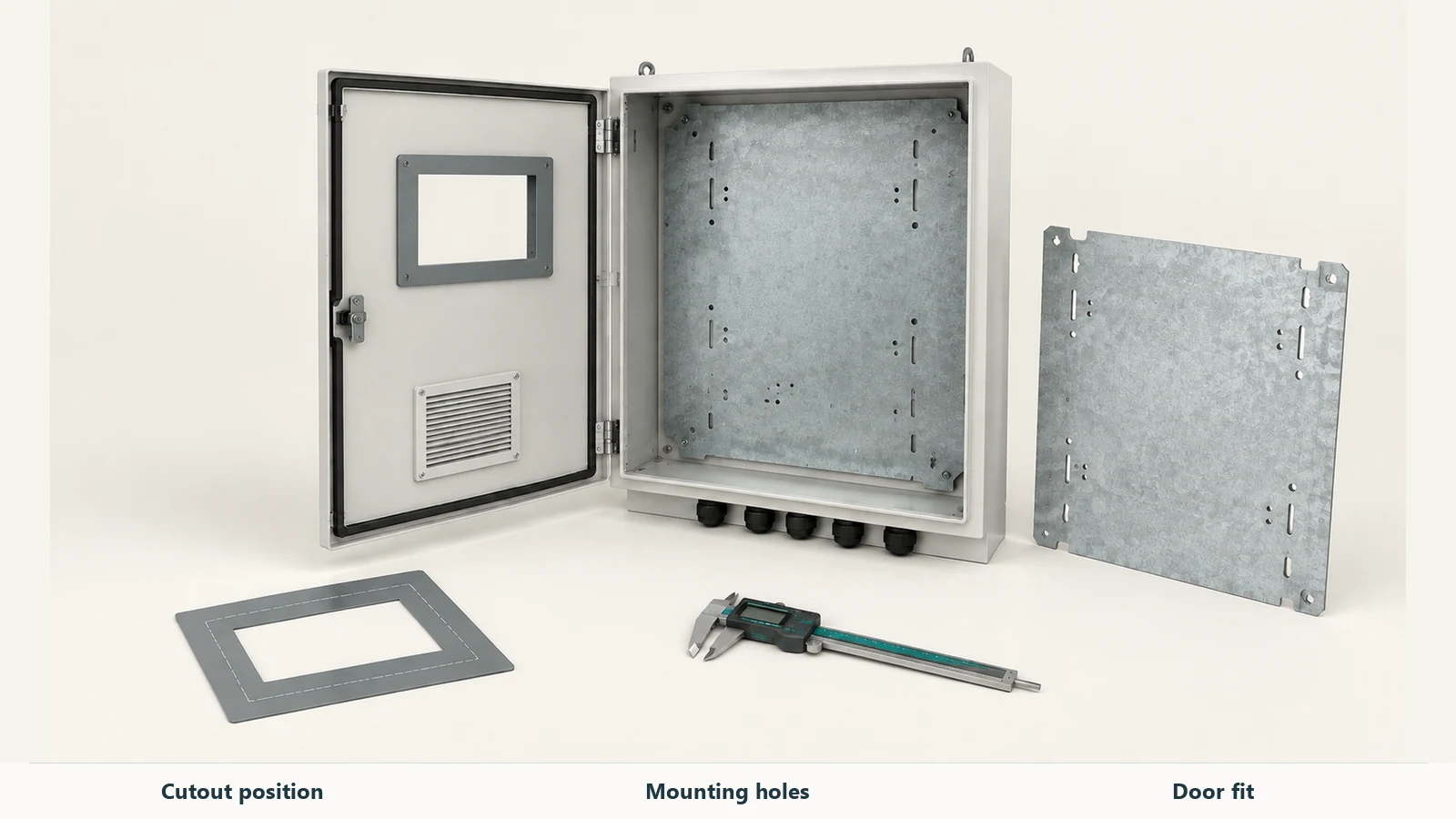
For a new design, you can also discuss a first-article review with us. Agree the checks that matter to assembly, such as cutout positions, mounting holes, door movement and accessory fit, before approving the batch.
Keep electrical design, programming, wiring and testing assigned to named parties. If you’re comparing quotes with different supply scopes, the guide to electrical enclosures versus control panels explains the distinction.
Check the approval scope as well. UL distinguishes an enclosure-only certification from certification of an enclosed industrial control panel; enclosure-only certification does not establish the compatibility of installed equipment and wiring.
FAQ
What drawings do I need for PLC control panel design?
Bring together the BOM, general arrangement, mounting and door layouts, electrical schematics, terminal plans, I/O schedule and communications architecture. Agree the required deliverables and revisions with your project team.
How much spare space should I leave?
Start with the additions you expect. An extra module needs its own space, terminals, wiring and service access. Check the extra control-power demand too. That gives you a more useful expansion plan than a percentage of empty plate area alone.
Can I ask for an enclosure quote while the design is still changing?
Yes. Send us your current sketch or layout and mark the open items. We can begin the enclosure discussion from there, then confirm the affected dimensions and interfaces on the production drawings.
Bring your layout to FN
Our industrial automation enclosures include cabinet bodies, doors and mounting plates with drawing-defined mechanical features. If you’re working through an HMI opening, device mounting or cable entry, send the layout and component references with your dimensions, material requirements and quantity.
You can review the custom enclosure options or contact FN with your project requirements. For drawing attachments, use the email address listed on the contact page. Include any installation or electrical-assembly requirements in your message so we can confirm the requested scope with you.