
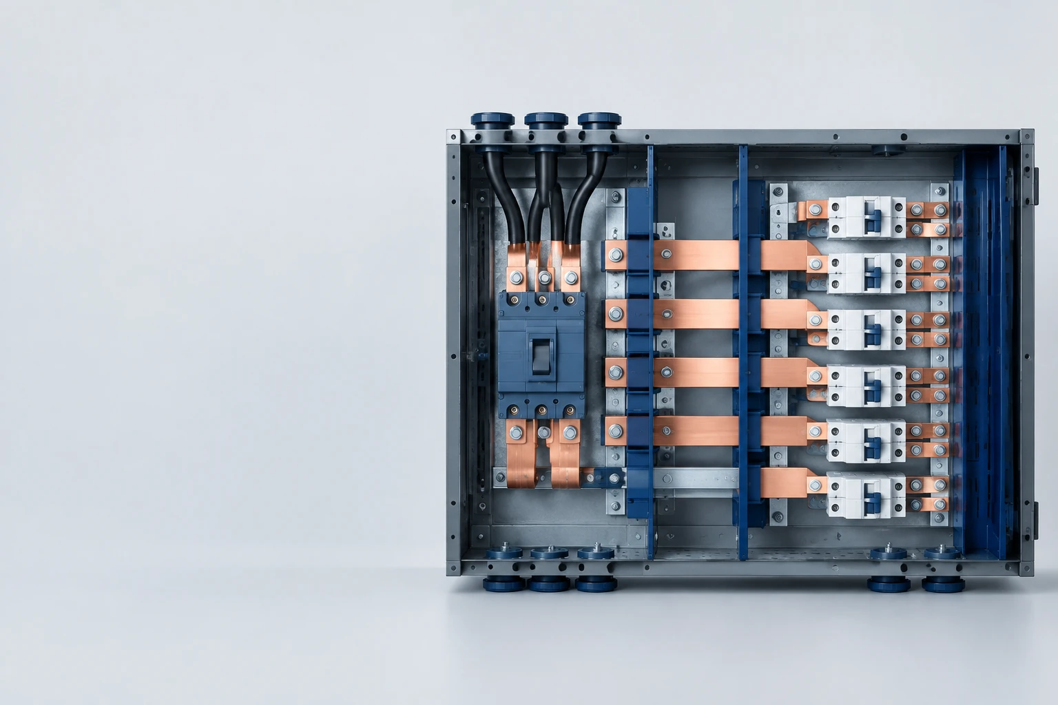

An electrical busbar is a metal conductor, usually copper or aluminum, that carries current between connection points. In an electrical panel, it provides a common path from the incoming supply to several outgoing circuits. You’ll also find busbars in switchgear, battery packs, and power-conversion equipment.
If you’re comparing panel layouts, the appeal is easy to see: a shaped bar can connect equipment in a space that would otherwise need several heavy cables and room for their bends. Whether that helps your project depends on the connections, available space, and electrical duty.
How Does a Busbar Work?
Picture a distribution panel with one incoming supply and several outgoing circuits. The supply connects to the busbar, and branch devices connect at points along it. Current flows through the bar to those connections.
A simplified branch path looks like this:
Incoming supply → busbar → branch protective device → outgoing circuit
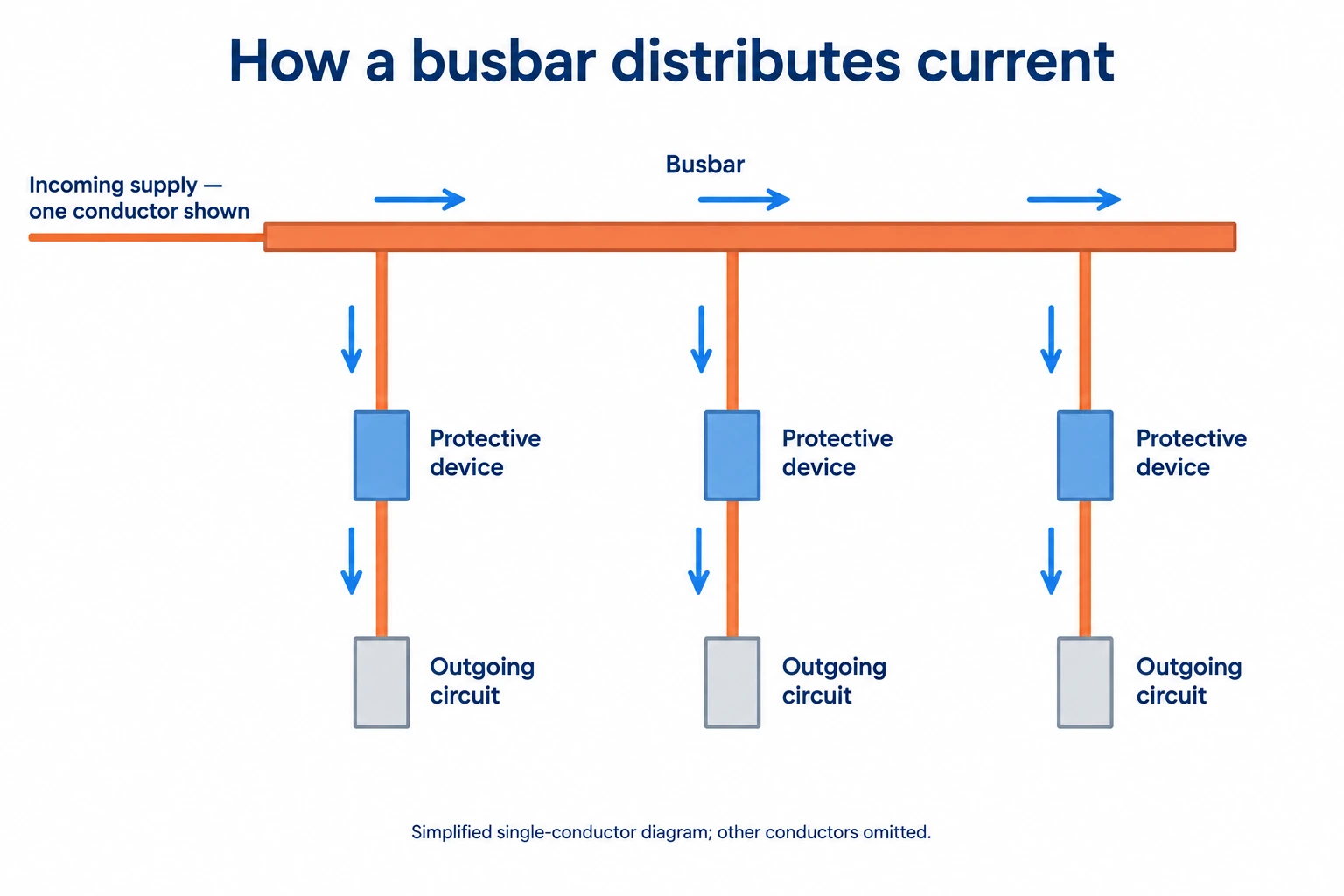
Connections might use bolts, clamps, or purpose-designed plug-in contacts. The busbar carries the current; breakers and fuses provide their respective protective functions. In a three-phase assembly, each phase normally has its own conductor.
The shape matters, too. It affects how the bar fits, releases heat, and behaves electrically. Ansys’s busbar overview explains how conductor geometry, cooling, and electromagnetic behavior influence the design.
You’ll see both bare and insulated busbars. Bare bars rely on the assembly’s spacing, barriers, and guarding. Insulated designs add a covering or insulation system around the conductors. Both need an arrangement suited to the equipment and its operating conditions.
What Types of Busbars Will You See?
A drawing may describe a busbar by its construction or by its job. A “copper busbar” tells you the material. A “neutral busbar” tells you its electrical role. Those descriptions can apply to the same component.
Rigid busbars
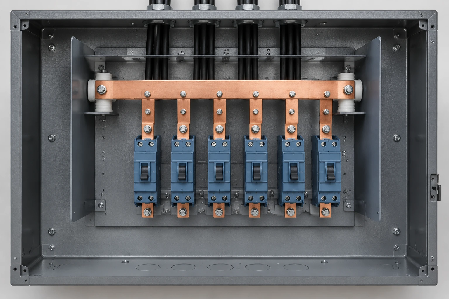
Rigid bars are common in panels and switchgear. They can be cut, drilled, and bent to place connections where the equipment needs them.
For your layout, look beyond the bar’s outline. Can you reach the joint hardware? Where do the supports attach? How much room remains between the bar, neighboring components, and enclosure walls? Those details affect assembly and later maintenance.
Flexible busbars
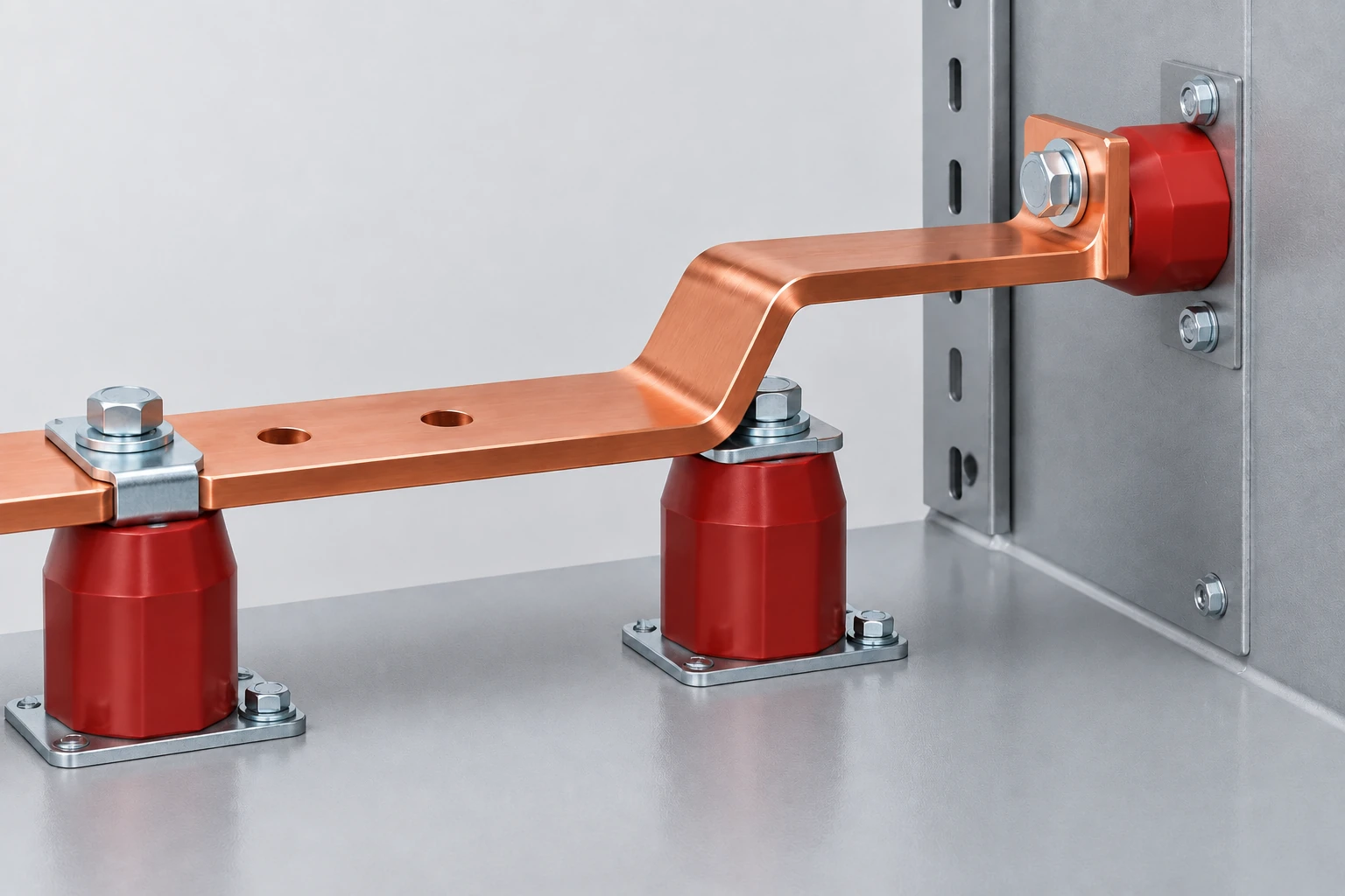
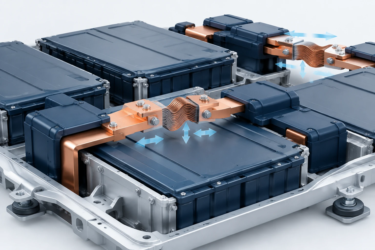
Flexible constructions accommodate movement, vibration, thermal expansion, or installation tolerance. They may use thin copper layers, braided conductors, or flexible sections at selected points.
For example, SMK’s battery connection project used flexible copper elements to address thermal expansion and driving vibration. If your connection needs to move, define that movement before choosing the construction.
Laminated busbars
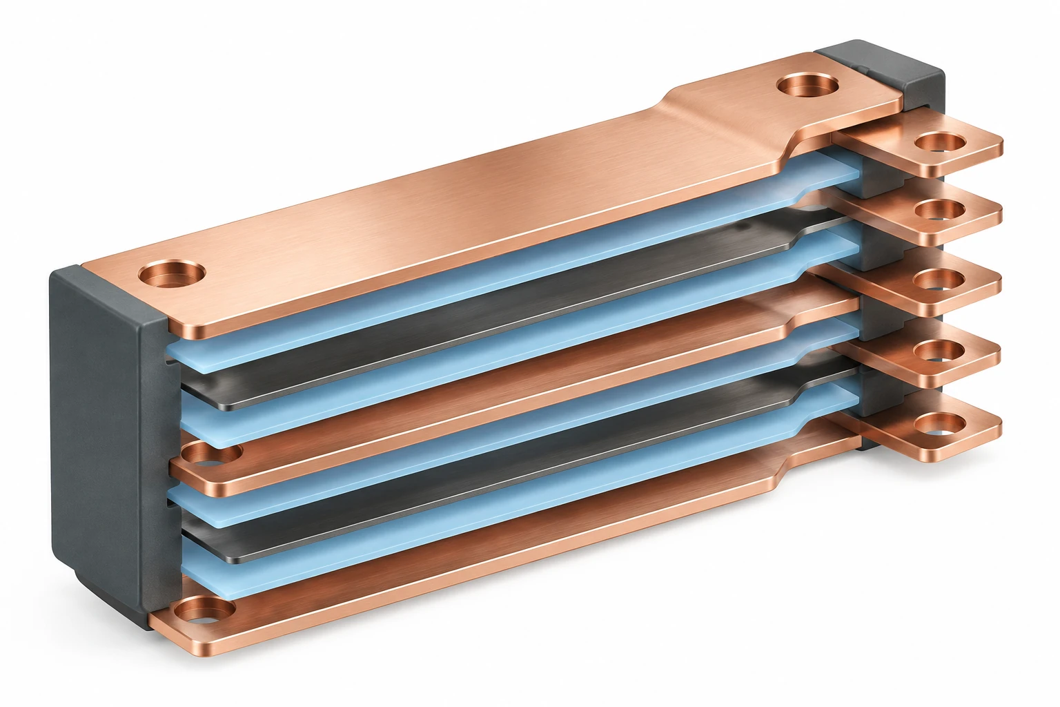
Laminated busbars arrange conductors in layers separated by insulation. Their controlled geometry can help manage inductance and organize connections in inverters, drives, battery systems, and other power electronics.
The layer arrangement, insulation, terminals, and heat path work together. You’ll want to review them as one design.
Phase, neutral, and protective-earth busbars
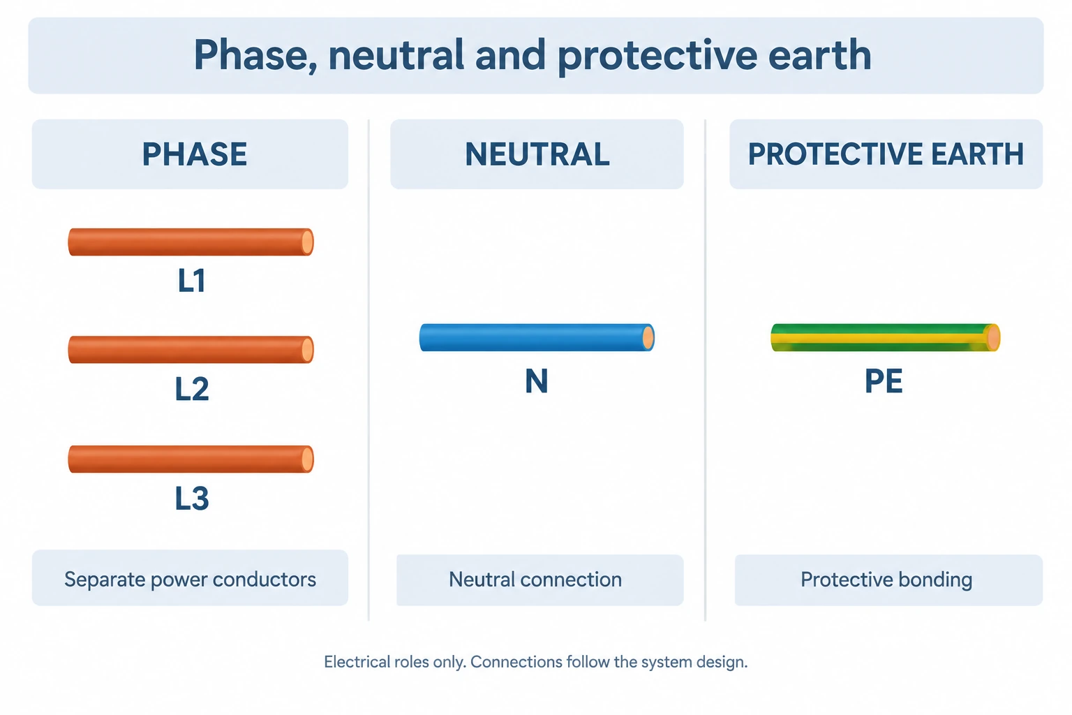
These names describe different electrical jobs:
- Phase busbars distribute power to connected circuits.
- A neutral busbar provides the neutral connection where the system requires one.
- A protective-earth or bonding bar connects the specified protective conductors or bonding points.
- DC busbars connect positive and negative power paths in suitable equipment.
Neutral and protective-earth conductors have distinct roles. Their connection or separation follows the supply arrangement and the installation design. Screening and shield-bonding bars also have a different purpose from phase power conductors.
Copper or Aluminum: Which Fits Your Project?
Copper offers higher conductivity for a given cross-section. Aluminum is lighter and can be attractive where weight or material cost matters and the layout allows a larger conductor.
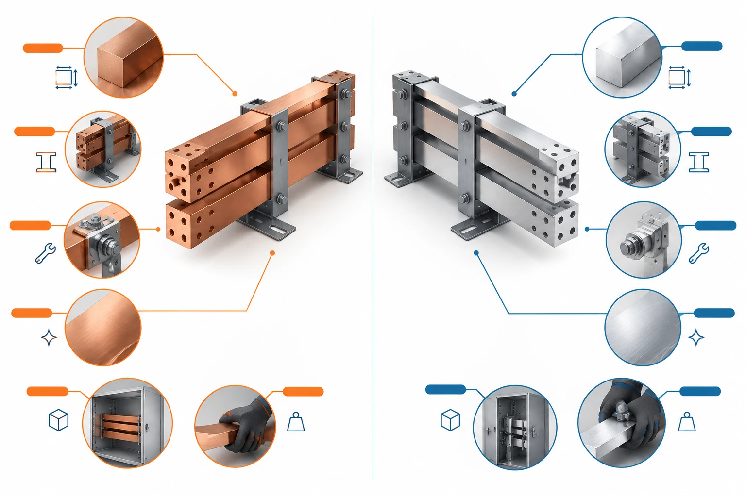
The useful comparison is how each material fits your complete assembly:
| Your priority | What to compare |
|---|---|
| Limited internal space | Required cross-section, clearances, and connection geometry |
| Lower weight | Conductor weight, support arrangement, and handling |
| Reliable joints | Compatible terminals, surface treatment, fastening, and specified torque |
| Operating environment | Temperature cycling, moisture, chemicals, and dissimilar-metal interfaces |
| Overall project cost | Conductor, connections, supports, fabrication, and enclosure space |
Joint quality matters with either material. A high-resistance connection can create a hot spot even when the bar itself has enough cross-section. Storm Power Components’ joint-resistance study examines how torque and plating affect the connection.
Where Are Electrical Busbars Used?
The same principle appears in several kinds of equipment, as outlined in LS Electric’s busbar guide:
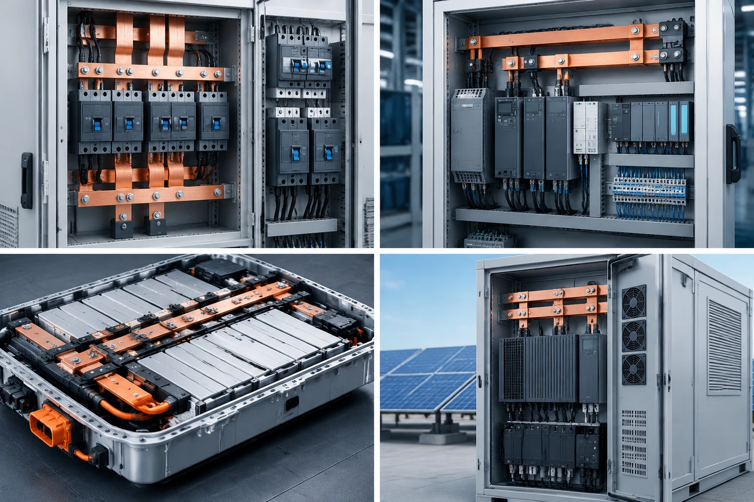
- In panelboards, switchboards, and switchgear, busbars distribute incoming power to branch devices and feeders.
- In industrial machinery, they provide defined connections within the equipment’s available space.
- In battery packs and electric vehicles, shaped or flexible conductors connect cells, modules, and power electronics.
- In solar, UPS, and conversion equipment, they connect sources, converters, protection, and loads.
- In buildings and data centers, enclosed busway systems distribute power along planned routes.
For a panel project, a power-distribution enclosure provides the surrounding structure, mounting surfaces, access, and cable-entry locations. These need to follow the internal electrical layout.
Busbar vs. Cable vs. Busway
These terms come up together in specifications, but they describe different things.
| Option | What you’re specifying | Where it can help |
|---|---|---|
| Busbar | A conductor or conductor set with defined connections | Compact internal layouts and repeatable high-current connections |
| Cable | An insulated conductor routed between connection points | Long, flexible, or field-routed connections |
| Busway | An enclosed distribution assembly containing busbars, supports, insulation, and joints | Planned distribution routes, including systems with tap-off points |
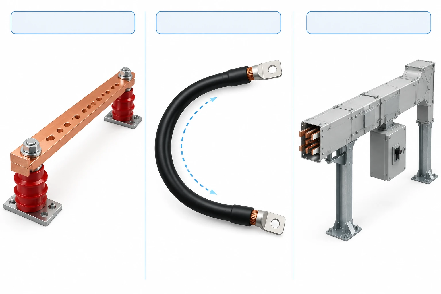
Busway is also called busbar trunking in some markets. Its housing, joints, and other components have to be assessed as a complete system.
For a panel, compare the finished layouts. Cable needs routing and bend space. A busbar needs its own supports, joints, insulation provisions, and service access. Rittal’s panel-builder comparison looks at busbar systems alongside traditional block-and-cable wiring.
In AMtec’s space-saving case study, cable bending space had contributed to oversized solar combiner enclosures. AMtec describes using custom busbars to reduce the footprint, then applying that approach to semiconductor power-distribution boxes. For your project, the useful question is how much space the complete connection arrangement needs.
What Determines a Busbar’s Current Rating?
When you see “400 A busbar” on a quotation, you need to know the conditions behind that number. Cross-section is one input. The finished arrangement also has to manage heat and withstand the specified fault duty.
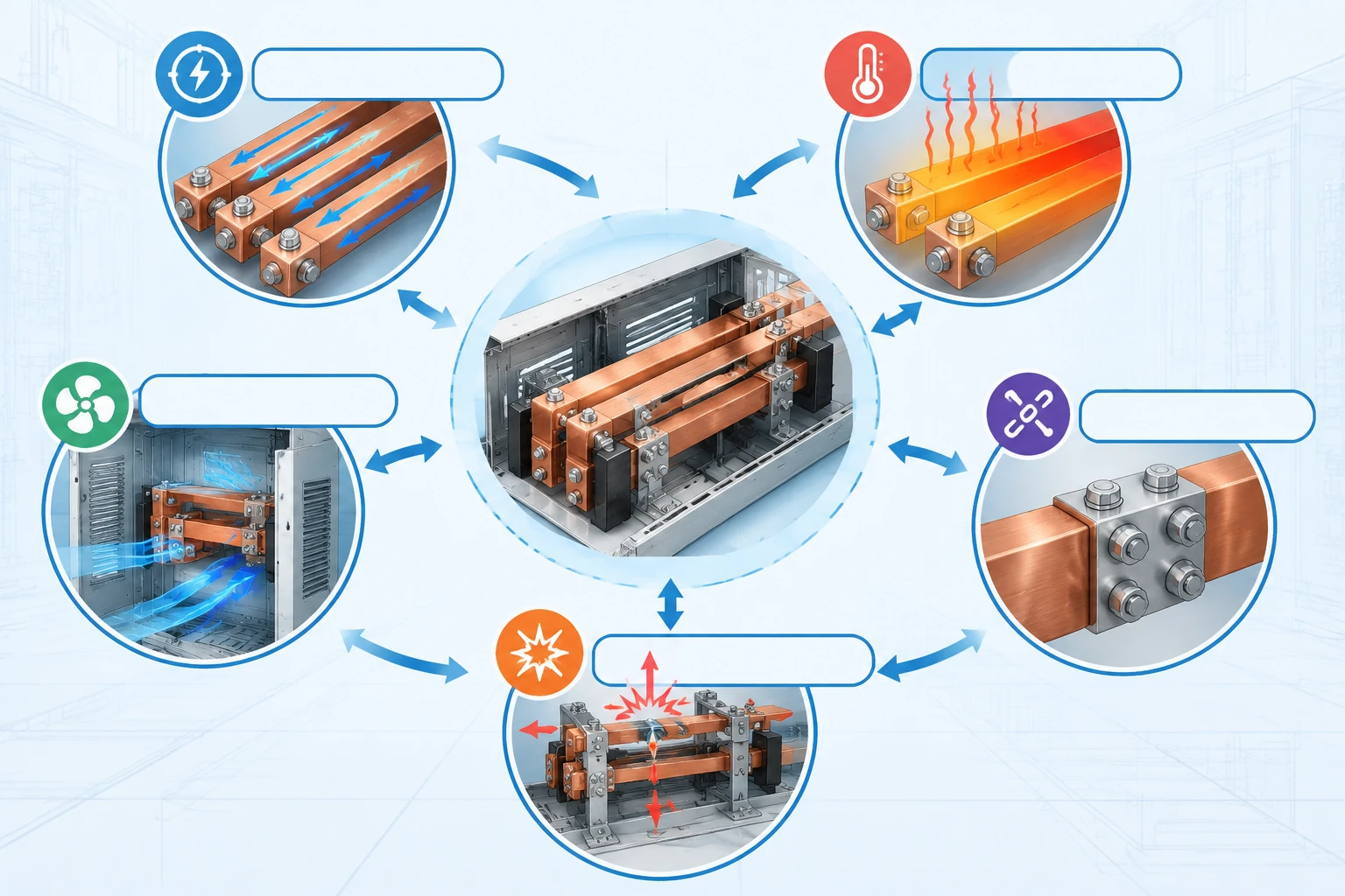
Four areas deserve a closer look:
- Load and temperature rise. Continuous current, duty cycle, ambient temperature, and nearby heat sources affect how hot the assembly becomes.
- Layout and cooling. Bar spacing, orientation, enclosure size, and ventilation influence how heat leaves the conductors and connections.
- Joints. Contact surfaces, hardware, torque, and support affect connection resistance and local heating.
- Short-circuit duty. The conductors and supports must withstand the heat and mechanical forces associated with the specified fault conditions.
Continuous-current capability and short-circuit withstand answer different questions. Your specification should address both, along with the protective devices used in the assembly.
Schneider Electric’s explanation of IEC 61439 rated current also distinguishes a device’s current capability from its performance inside an assembly. The applicable equipment standard and verification route belong in the project specification; the IEC 61439-1 publication record provides the general assembly-standard context.
For the enclosure discussion, bring the thermal and clearance requirements with the electrical layout. That gives the mechanical design a defined space to work around.
What Can Go Wrong Around a Busbar?
Three areas are worth considering while the layout is still easy to change.
Connections that run hot
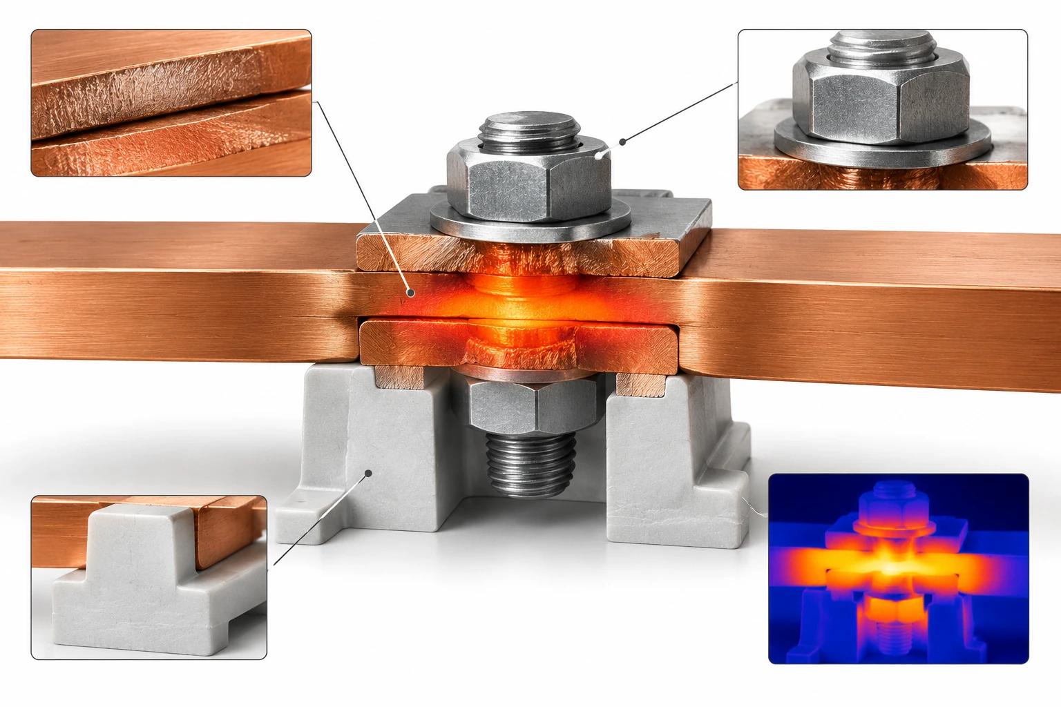
Loose, contaminated, or poorly prepared joints can increase resistance and concentrate heat at a connection. Joint hardware, surface condition, and assembly instructions need attention alongside conductor size.
Access matters here. Your team needs enough room to assemble and inspect the connection using the specified procedure.
Insulation problems
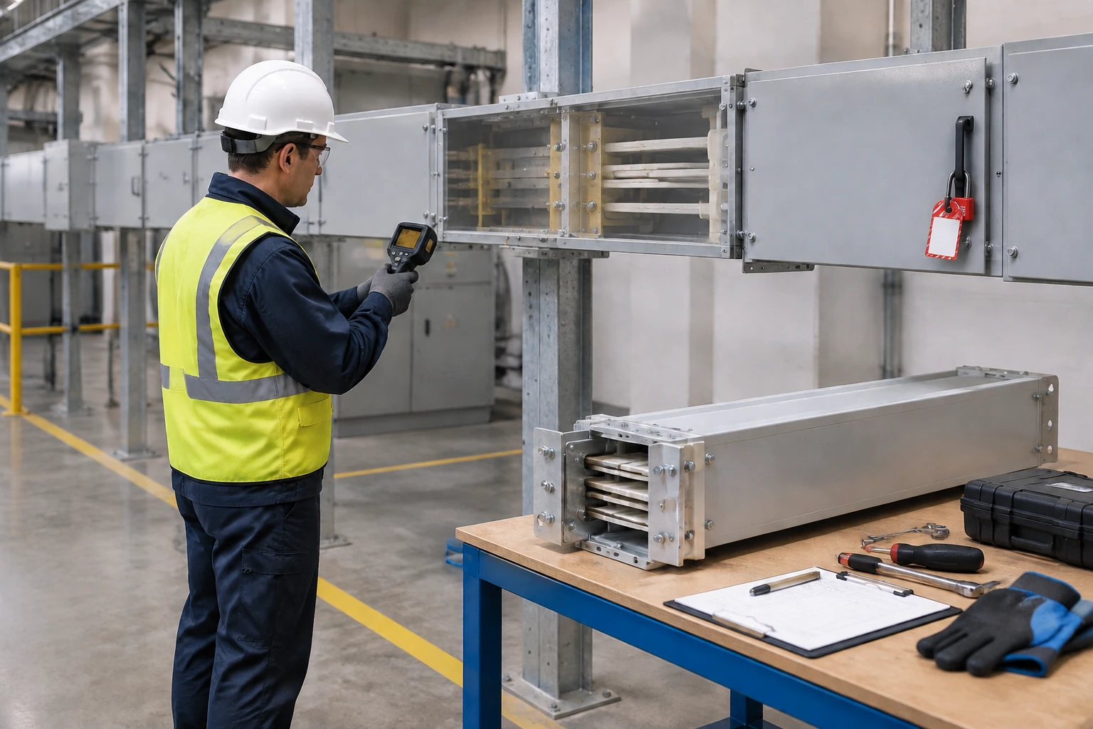
Insulation defects or contamination can create discharge paths. In TEGG’s UPS distribution case, ultrasonic inspection identified signs of internal insulation breakdown. The team transferred the load and replaced the affected section during a planned shutdown.
The case illustrates a maintenance consideration: the inspection approach needs to suit the fault being investigated, and the layout needs to allow the required access.
Supports or access that don’t suit the installation
Short-circuit forces place demands on the supports and fastening arrangement. Installation and maintenance bring another set of questions: can you reach the joints, remove the required cover, and route the cables without crowding the bar?
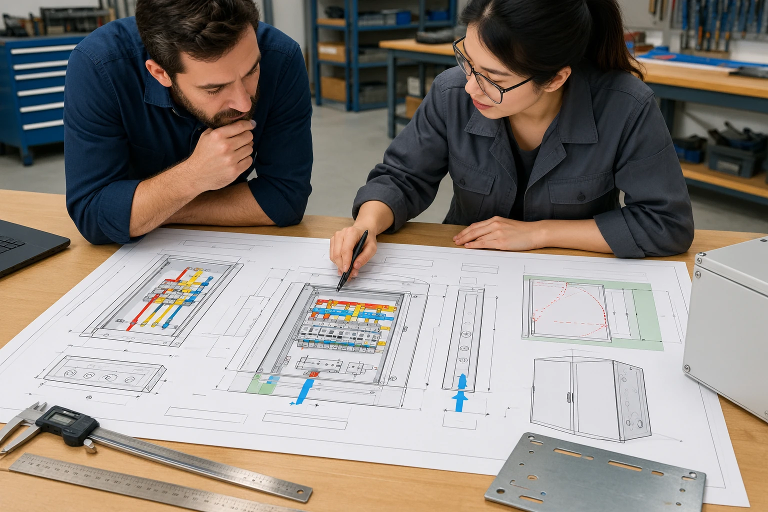
These are useful items to mark directly on the enclosure drawing, while mounting points and access details can still be coordinated.
What Should You Confirm Before Ordering a Panel?
Start with what you’re buying: an enclosure, a busbar assembly, or a complete wired panel. Then use the drawing and quotation to answer these questions.
What are the electrical and environmental requirements?
Record voltage, phase arrangement, continuous current, duty cycle, fault level, protection, and ambient conditions. Include the installation environment, such as indoor use, outdoor exposure, dust, moisture, or chemicals. This gives the suppliers a common brief.
Will the internal layout fit and remain accessible?
Show the busbars, supports, barriers, connected equipment, cable routes, and clearances. Include room for cable bends, door movement, removable covers, and tools at the connections. Our electrical enclosure sizing guide helps organize those space requirements.
For an existing installation, check the actual interfaces. In COMECA’s switchboard-extension project, the team measured existing cabinet sections and busbar positions before designing the connection to a new section. Those dimensions determined how the extension would fit.
Which details need to be fixed before fabrication?
Agree on mounting locations, hole patterns, cutouts, cable entries, material, doors, sealing, and handling requirements. Put them on the approved drawing revision, together with quantity and any project-specific inspection requirements.
What will each supplier deliver?
List the enclosure parts, mechanical accessories, busbar components, wiring, and documentation against the party providing them. Assign electrical sizing, protection coordination, and complete-assembly verification to the electrical designer or assembly supplier. That leaves a clear mechanical package for the enclosure manufacturer to build.
For the cabinet’s role in the complete assembly, see what an electrical enclosure does.
An Enclosure Built Around Your Busbar Layout
At FN Enclosure, we build wall-mounted enclosures, floor-standing cabinets, and junction boxes to project drawings. That means you can start with the space your components and connections need, rather than work backward from a fixed catalog size.
The practical details might be an extra allowance behind the busbar, a mounting point that needs to line up with a support, or a cable entry that has to clear the incoming connection. Your drawing gives us the basis for reviewing those requirements before fabrication.
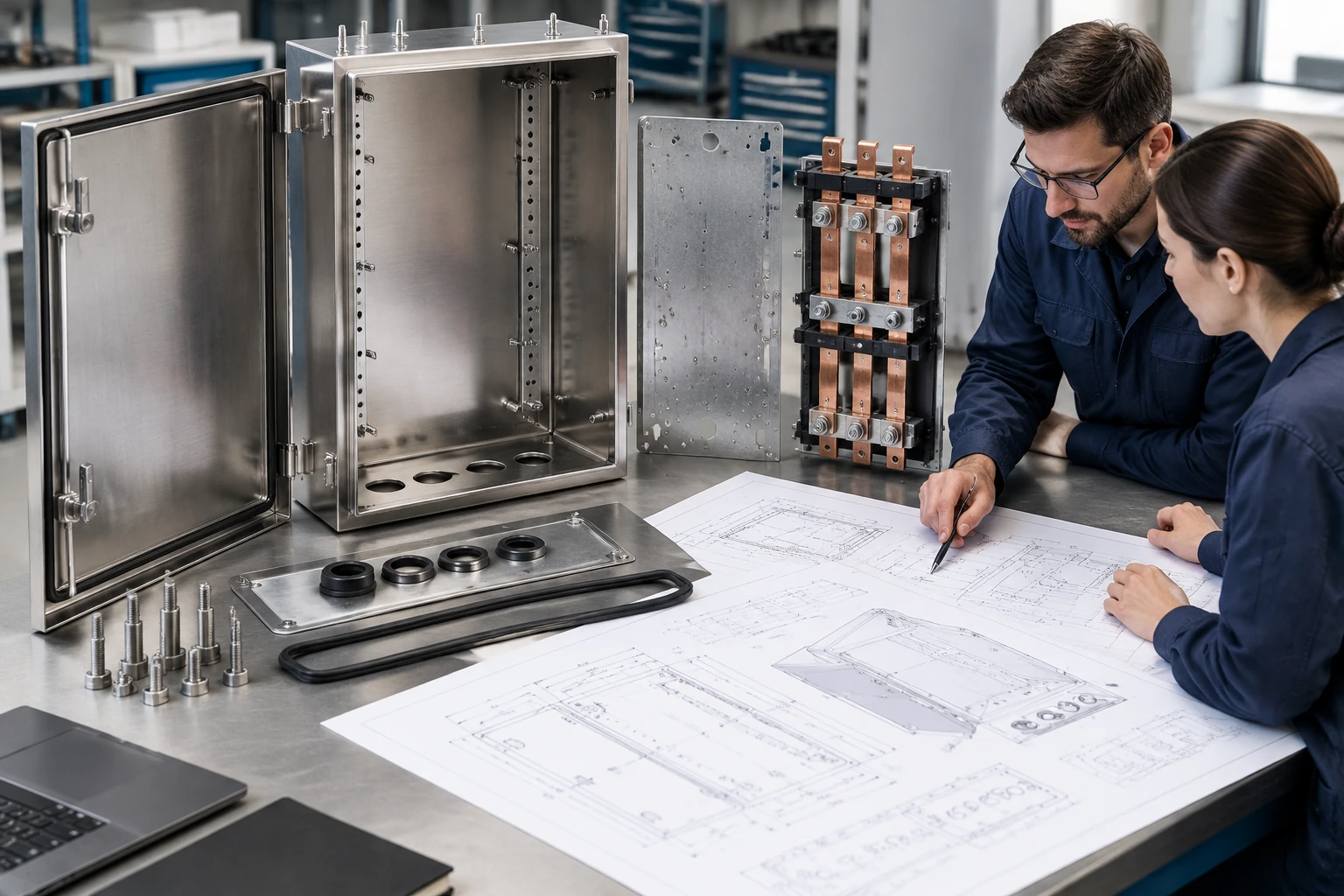
For stainless-steel enclosure projects, our drawing and manufacturing review brings the cutouts, mounting features, doors, and sealing details into one approved production revision. You can compare the proposed enclosure with your panel layout while those details are still on the drawing.
If your stainless-steel enclosure order includes a first article, the inspection and approval stage gives you a chance to check the agreed mechanical details before batch production. We agree on the production drawings, inspection report, and packing photos with your order, giving your receiving team references for checking the delivery.
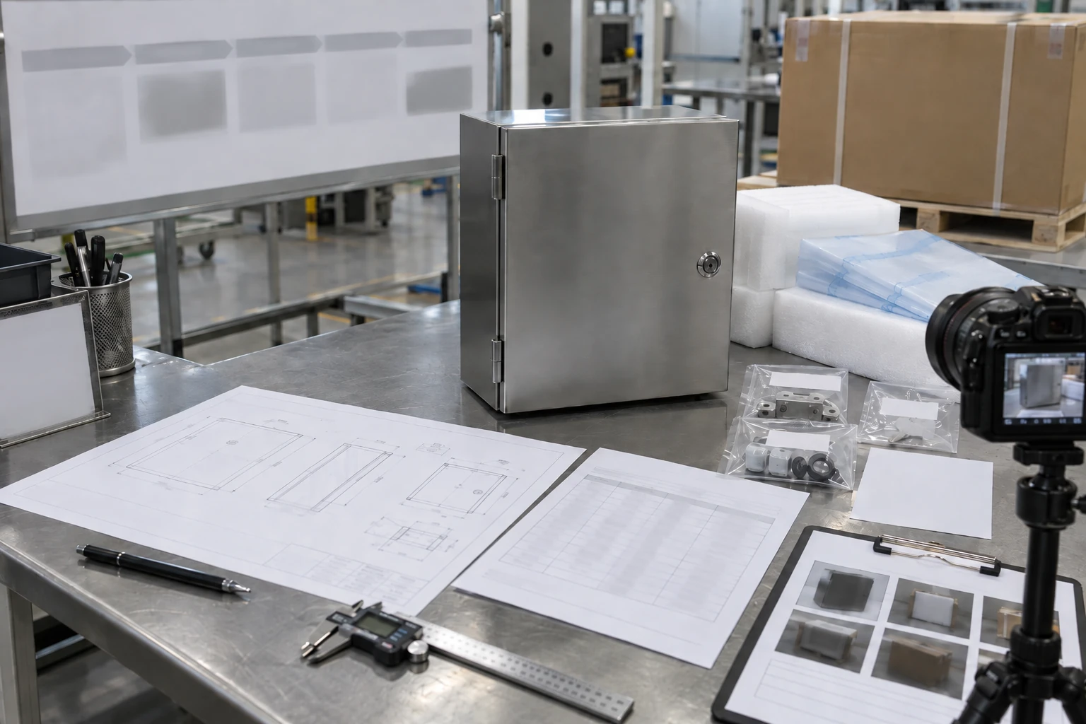
You can explore our custom electrical enclosures or send your layout for an enclosure review. Include the overall dimensions, material, mounting points, openings, cable-entry direction, access requirements, and quantity. Those details help us review the enclosure you need around your panel design.
FAQ
Is a busbar the same as a circuit breaker?
A busbar carries and distributes current. A circuit breaker switches a circuit and provides defined protective functions. They connect within the panel but perform different jobs.
Can a busbar replace a cable?
Yes, in a layout designed for it. Busbars can suit compact, repeatable connections; cables offer routing flexibility. Compare the finished arrangement, including insulation, supports, terminations, and maintenance space.
Which is better, copper or aluminum?
Copper offers higher conductivity per cross-section. Aluminum offers lower weight. The choice comes down to available space, current duty, connections, operating conditions, and the cost of the complete arrangement.
Are neutral and protective-earth busbars interchangeable?
They have different electrical roles. Their connection or separation depends on the supply system and the installation point. Use the arrangement specified in the electrical design.