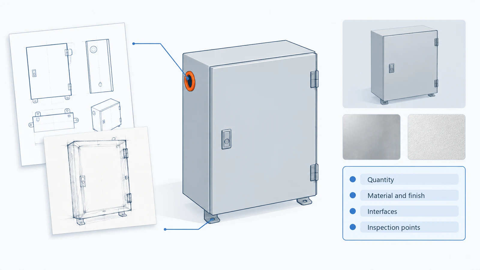
If you’re comparing switchgear vs switchboard options for a U.S. low-voltage project, start with how the equipment is built and how you’ll maintain it. Switchboards commonly group feeder breakers into a compact assembly. Low-voltage power circuit breaker switchgear uses individually mounted breakers and separate compartments. The assembly standard, fault ratings and access arrangements help you decide which fits your project.
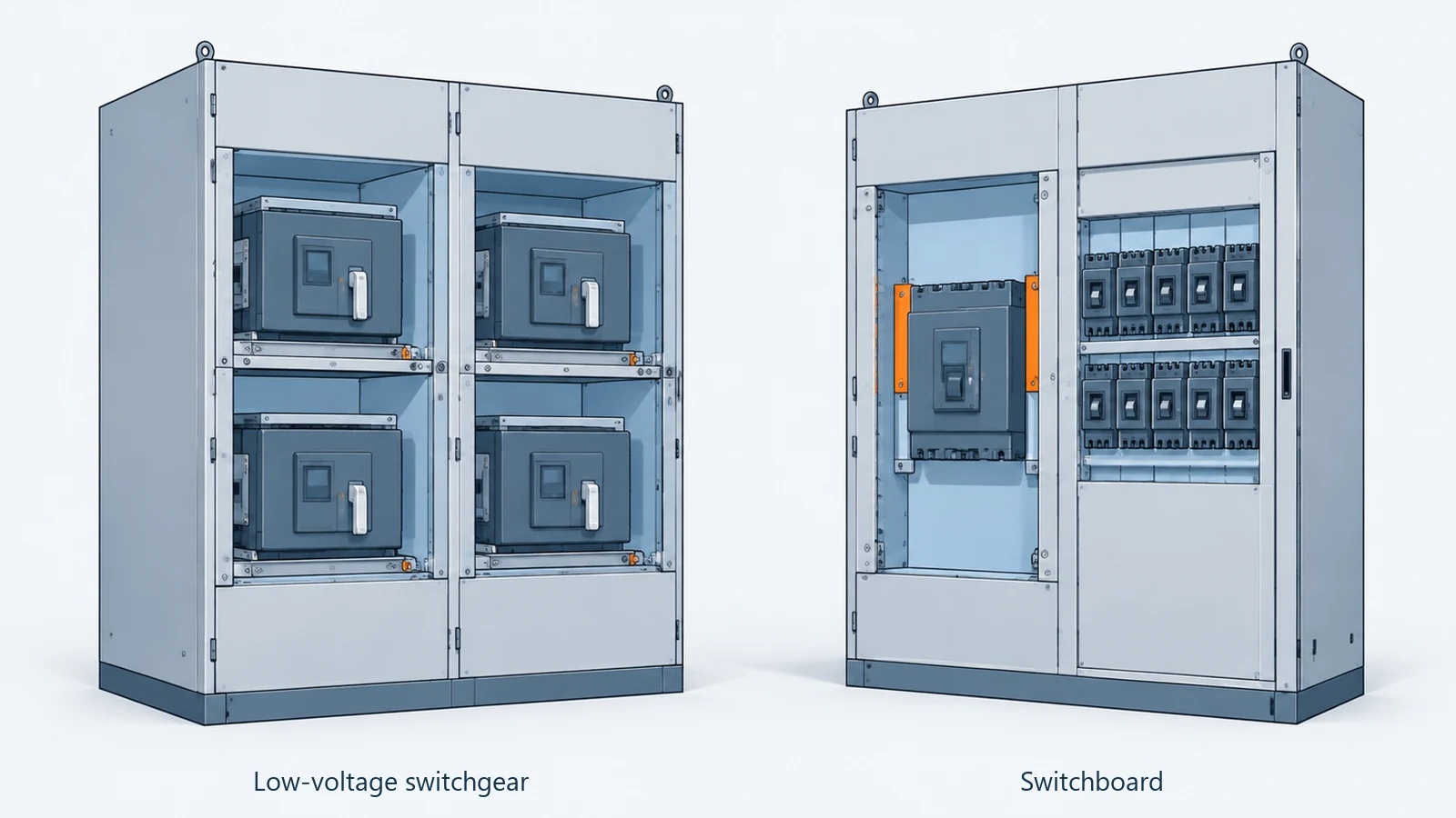
Switchgear vs switchboard at a glance
Both receive power and distribute it to outgoing circuits. For the equipment covered here, UL 891 is the switchboard standard; UL 1558 covers metal-enclosed low-voltage power circuit breaker switchgear.
On mobile, scroll tables sideways to compare all columns.
| What you’re comparing | Switchboard | Low-voltage power circuit breaker switchgear |
|---|---|---|
| Assembly standard | UL 891 | UL 1558, with related IEEE/ANSI standards |
| Common protective devices | Molded-case or insulated-case breakers; other configurations are available | Low-voltage power circuit breakers |
| Breaker arrangement | Group-mounted feeders are common; individual and drawout options are available | Individually mounted breakers in separate compartments |
| Fault-duty information | Assembly SCCR, device ratings and any specified combination conditions | Assembly fault ratings and the required short-time withstand current and duration |
| Access | Front-access layouts are common; some designs need rear access | Front-access and rear-access products are available |
| Space | Group-mounted designs can fit more feeders into a compact structure | Compartments and service access affect the layout |
The table combines UL’s assembly guidance with Eaton’s construction and product examples. Your supplier’s drawings will show how those features fit together in the proposed equipment.
For projects outside this U.S. framework, use the assembly standard named in your specification; local terminology can differ.
What to look for in the ratings
Two quotations might show the same kA figure. Before treating them as equivalent, check what each figure describes. The breaker and the complete assembly have different rating information.
| Rating | What it tells you | What to ask for |
|---|---|---|
| Breaker interrupting rating | The fault current the breaker is rated to interrupt at the stated voltage and test conditions | Breaker model, rating and any applicable combination information |
| Assembly short-circuit current rating, or SCCR | The assembly’s suitability for the available fault current under its marked conditions | Assembly rating documentation and any required upstream protection |
| Short-time withstand rating | The current the equipment can carry for a stated short duration under specified test conditions | Current and duration together, with the equipment the rating applies to clearly identified |
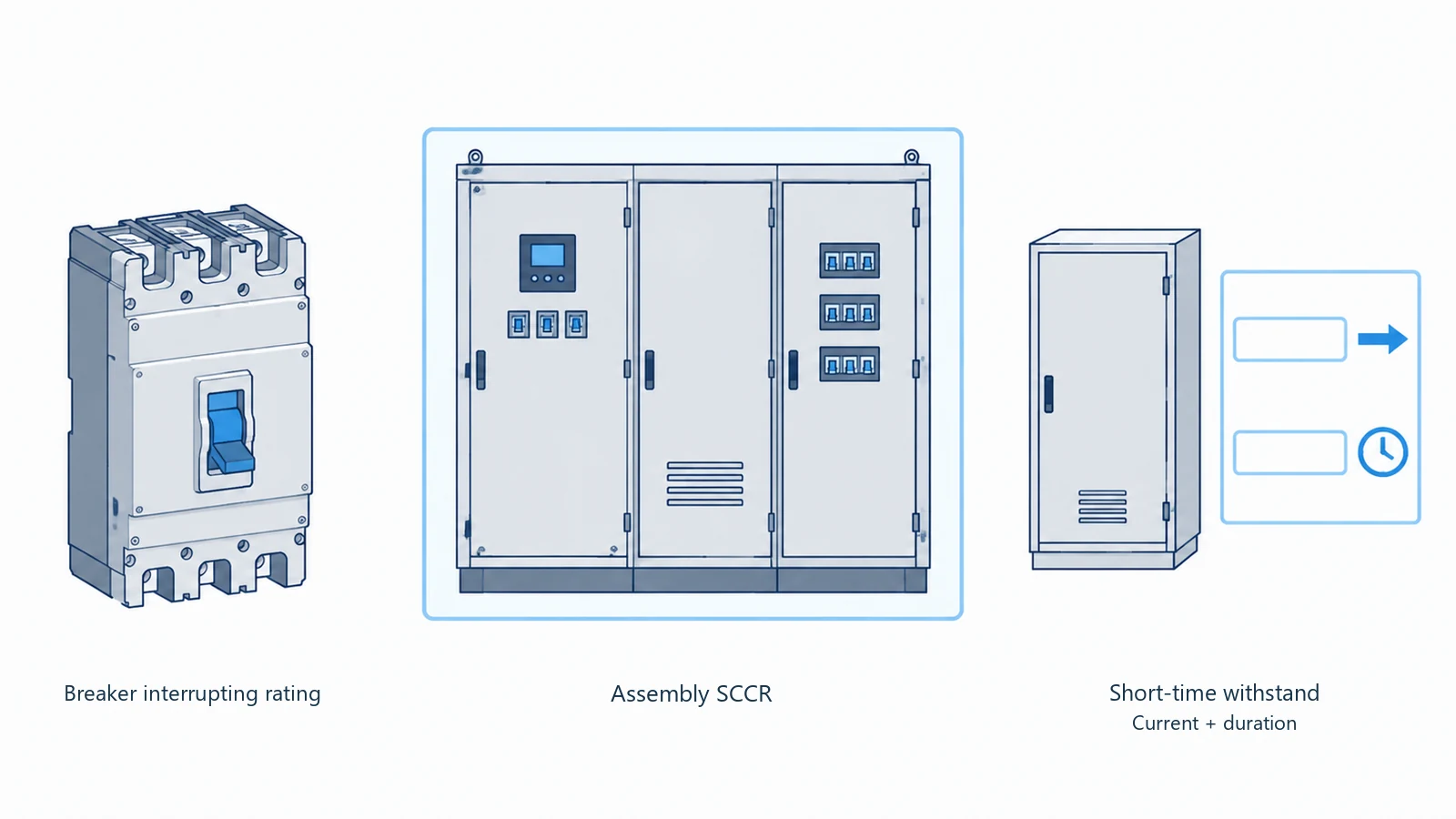
UL treats breaker interrupting ratings and switchboard SCCR separately. Schneider’s explanation of short-time withstand also ties the rating to a current, a duration and product test conditions. Its breaker-level Icw value belongs in the breaker information, with the assembly’s rating recorded separately.
Give your electrical designer those details alongside the fault study and proposed protection settings. If the protection scheme uses an intentional delay, ask them to check that the equipment can withstand the current for the required time. A quote is much easier to review when these values have their own labeled fields.
Which one fits your project?
Your specification is a useful starting point. If it calls for UL 1558 switchgear, ask suppliers to quote that assembly category and identify any proposed substitutions. UL 1558 has its own scope and references IEEE C37.20.1 and ANSI C37.51, so matching an ampere rating covers only part of the comparison.
If the specification permits UL 891 and a switchboard meets the electrical, operating and access requirements, you have a practical option to evaluate. Ask for certification evidence for the offered assembly alongside the device schedule. Individual component certificates cover those components; the assembly has its own requirements.
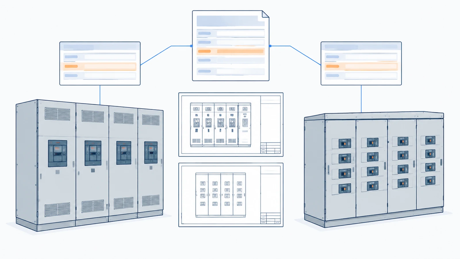
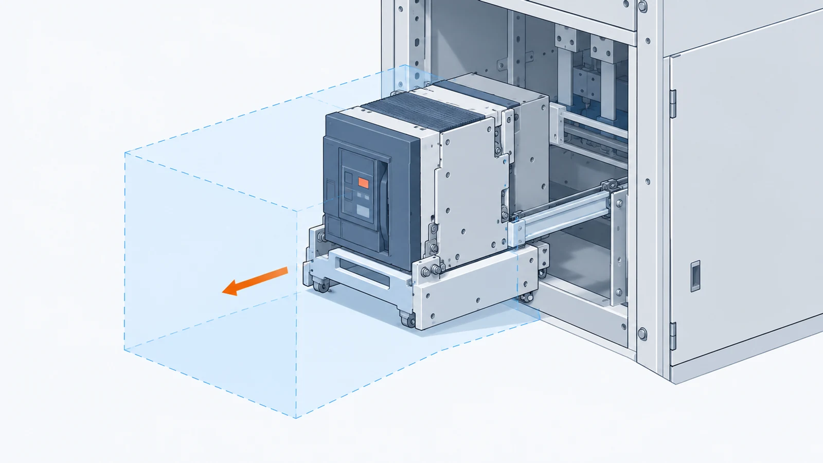
Then picture a maintenance job. Which section would your team isolate? Which circuits could stay available under the approved operating plan? How would a breaker be removed and replaced? Ask the supplier to walk through that arrangement on the drawing.
Drawout capability is worth checking by model. Eaton offers switchboards with drawout feeder breakers, so you can compare that feature directly rather than assume it belongs only to switchgear. For the work itself, follow the manufacturer’s isolation instructions and the applicable safe-work procedures, including OSHA’s de-energization and verification requirements.
Will it fit the room and the existing cables?
If space is tight, get the general arrangement early. Eaton’s front-access UL 1558 switchgear is one example of a product intended for constrained locations. Some switchboards, meanwhile, use rear access. The actual layout will tell you what room you need around the equipment.
For a replacement project, show the supplier:
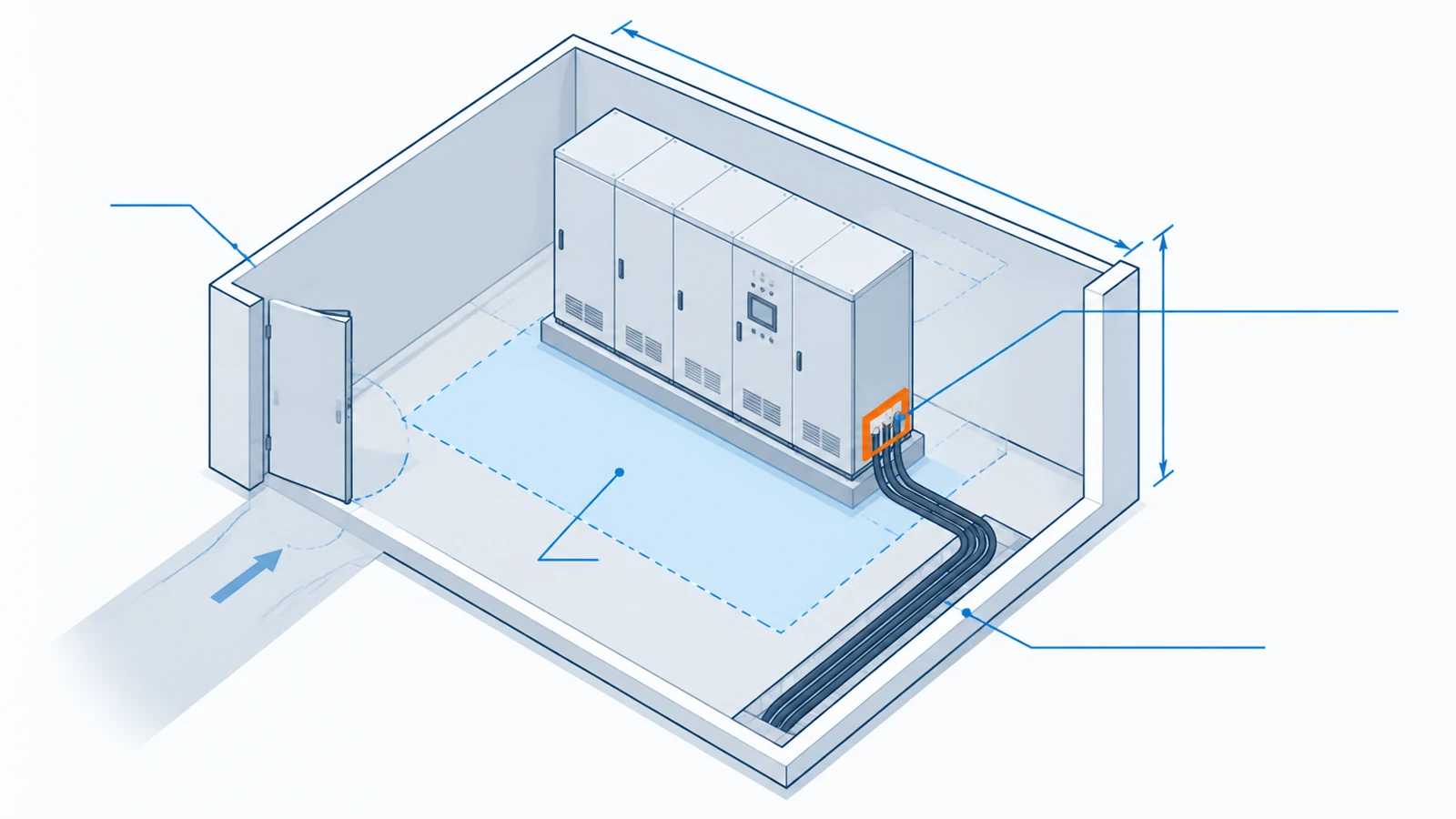
- The room dimensions, door openings and service access.
- Existing cable lengths, entry directions and termination positions.
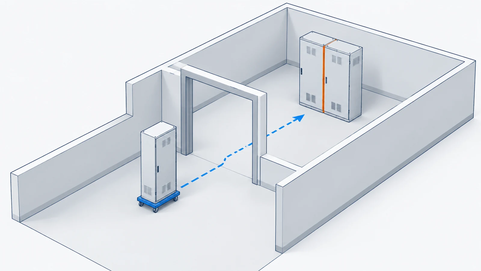
- The delivery route, lifting provisions and limits on shipping-section size.
- The base, anchors and connections to be made on site.
Prism Power describes a London headquarters project where a UK energy supplier wanted to retain its existing cables while adding metering. The new switchboards also had to fit a confined space and travel to the installation room in sections.
If you’re dealing with a similar replacement, an annotated room drawing gives suppliers something concrete to work with. Show where the existing cables end and ask them to mark the proposed terminals and section joints on their layout.
Make the quotations easy to compare
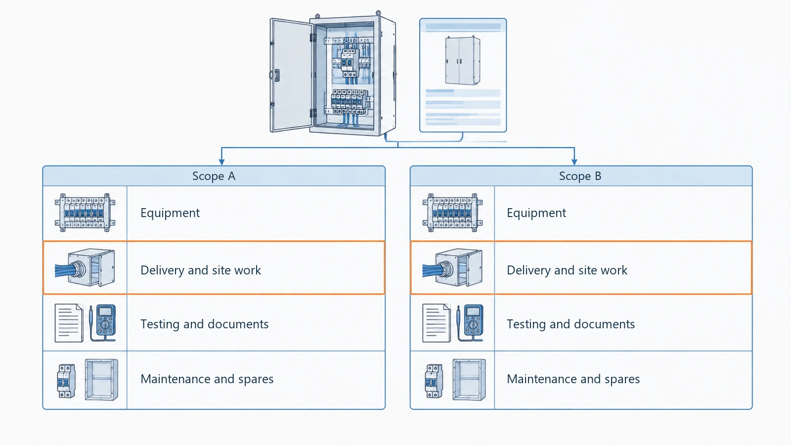
Give each bidder the same device schedule and installation information. Then ask them to show what’s included in these four areas:
- Electrical equipment, ratings, metering and controls.
- Delivery, lifting, field connections, cable work and room modifications.
- Factory and site acceptance testing, commissioning and the required documents.
- Maintenance access, spare devices and the planned replacement outage.
One proposal may include site connections while another prices delivery only. Putting those items side by side helps you see what still needs a separate price.
It’s also worth separating the schedule into drawing approval, manufacturing, testing, delivery and installation. Ask which dates depend on your approval or component availability, and who is arranging site work. That gives you a clearer route from placing the order to putting the equipment into service.
How FN helps you prepare the enclosure for your build
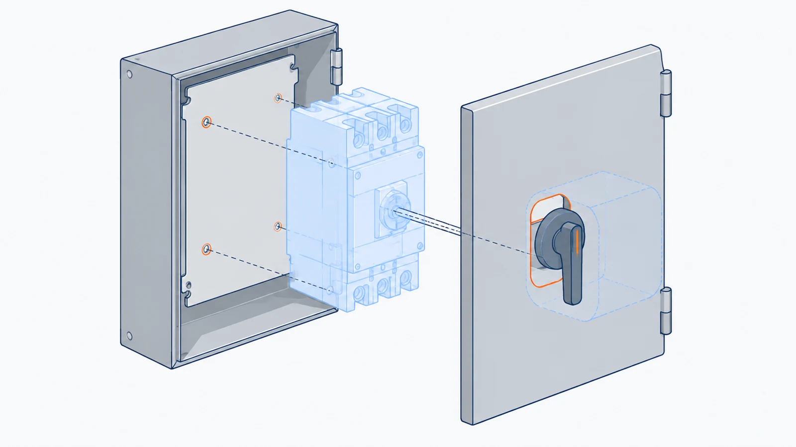
When you get to the enclosure drawing, you’ll want to see where the breaker sits, how its handle lines up with the door opening, and where the cables enter.
At FN, we review those mechanical details against your drawings before production release. Our power distribution enclosure work covers the body, doors, mounting plates, partitions and agreed mounting or cable-entry features. You can check how the parts will fit before approving the enclosure drawing.
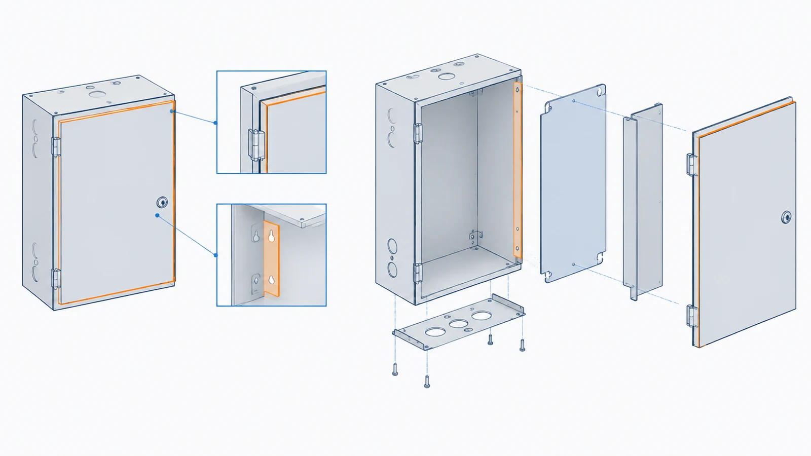
Check the details that affect assembly
A device change can mean another mounting pattern or a different door cutout. These are the interfaces we work through with you:
| What you’re working out | What we review | What you can confirm on the drawing |
|---|---|---|
| Breaker model and operating handle | Mounting pattern, door cutout and operating space | How the device and door interface fit together |
| Busbar route and supports | Support positions, partition openings and your specified clearances | Where the mechanical supports belong |
| Cable size and entry direction | Gland plate, termination zone and usable depth | The space allocated for cable approach and connection |
| Compartments and service access | Partitions, removable panels and door sequence | How the enclosure is assembled and accessed |
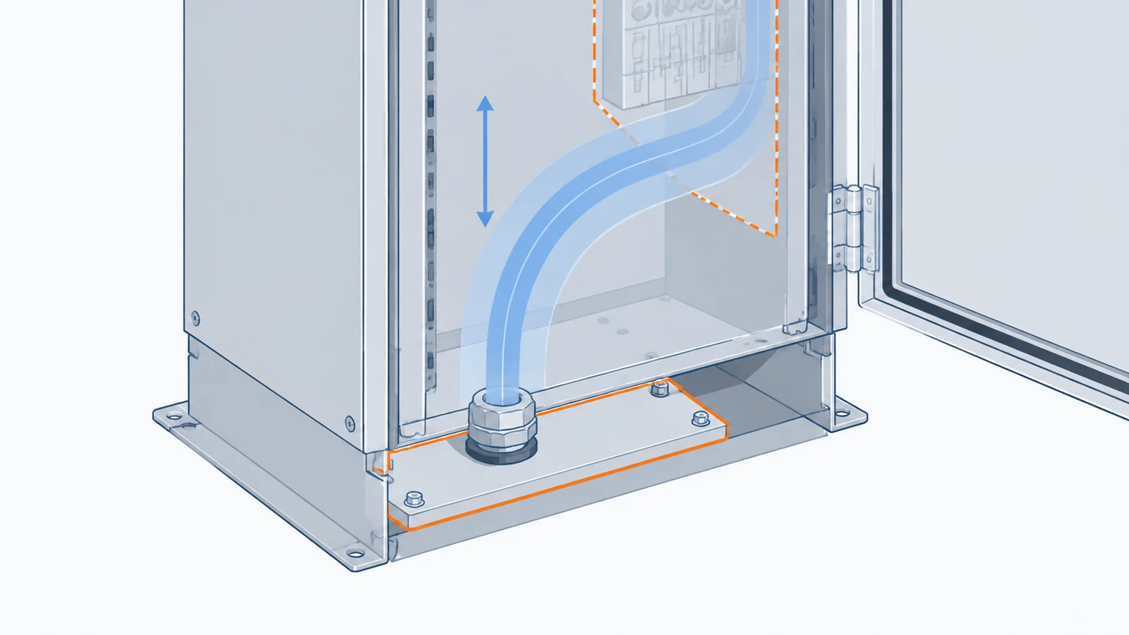
Your panel builder handles the electrical design and complete-assembly verification. We manufacture the enclosure and agreed mechanical parts to the approved drawing.
Give your team clear approval points
Our custom enclosure review covers openings, mounting interfaces, door and gasket fit, material, finish, inspection points and packaging. We also confirm the drawing revision and quoted scope, so you have a common reference for the quotation, first article and production work.
For the first article, agree the details your team wants to inspect: mounting-hole positions, door alignment, hardware fit, finish or other project-specific checkpoints. That gives you specific items to review and approve before moving to the batch.
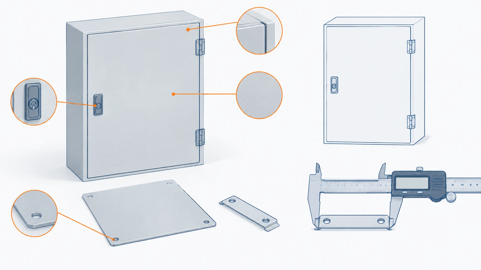
You can start the discussion with a CAD or PDF drawing, a sketch, a photo, a sample or a specification. Mark any open questions on what you send. We’ll use that information to work through the mechanical requirements and identify what the quotation needs.
If you’re deciding which parts of the build to source separately, our electrical enclosure vs control panel guide breaks down the order scope.
FAQ
Are switchgear and switchboards both available at low voltage?
Yes. The UL 1558 equipment discussed here is low-voltage power circuit breaker switchgear. When comparing it with a low-voltage switchboard, look at the assembly standard, construction and ratings as well as voltage.
How do I specify arc-resistant switchgear?
Put the required arc-resistant construction in the specification and ask for supporting documentation for the offered configuration. Eaton lists an arc-resistant offering for its front-access product; that feature needs to be identified in the proposal.
Have an enclosure drawing you’d like us to review?
Share the drawing or reference you have, along with the quantity, material and finish, device interfaces and cable-entry requirements. Include any inspection points that matter to your build.
We’ll review the enclosure requirements with you and work through the details needed for a quotation.