

Cable gland water ingress usually starts at the complete cable-entry assembly. Check the cable-to-gland seal, gland-to-plate interface, plate-to-enclosure joint, spare openings, routing, and condensation before replacing hardware.
What is a gland plate? A gland plate is a removable panel used to control cable-entry holes and sealing interfaces. It can simplify machining and inspection, but it adds a plate-to-enclosure joint that must remain flat, clean, and evenly compressed. The quoted scope should state whether it includes only the plate or also the glands, blanking parts, gasket, and assembly.
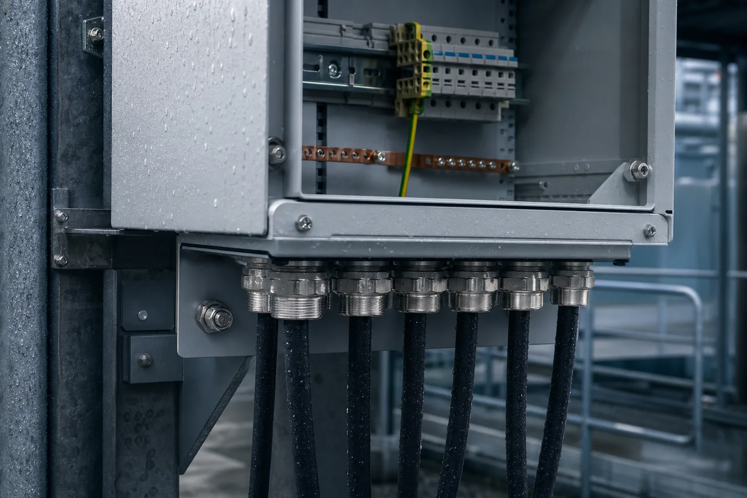
The short answer
Cable gland water ingress is usually a complete-entry problem, not a single-gland problem. Before replacing hardware, check the cable-to-gland seal, the gland-to-plate interface, and the plate-to-enclosure joint. Then check unused openings, cable routing, and condensation.
For a removable gland plate, the three main interfaces are:
- Cable to gland: the seal must match the cable’s actual outside diameter, published sealing range, and jacket condition.
- Gland to plate: the thread, hole, washer or O-ring, locknut, and plate surface must work together.
- Plate to enclosure: the perimeter gasket needs a clean, flat mating surface and even compression.
A good enclosure body and door gasket cannot compensate for the wrong cable diameter, a missing entry seal, a distorted gland plate, a damaged sealing surface, or an open spare hole. Proper cable gland sizing starts with the installed cable’s actual OD, not only the thread label.
This guide is for engineers, fabricators, installers, and buyers who are selecting a cable entry plate, reviewing a gland plate drawing, or troubleshooting water ingress in an electrical enclosure. For broader enclosure selection, see our guide to electrical enclosure selection.
Why the gland is waterproof is not a diagnosis
A cable gland rating describes a product under specified conditions. It does not prove that the complete enclosure assembly will resist water in the installed orientation. The final water path can run through the cable seal, the gland-to-plate interface, the plate perimeter, an unused opening, the cable route, or a condensation cycle.
Before drilling, before tightening, and before blaming the gland, follow the complete installed path. The five cases below show why orientation, blank positions, humidity, below-grade exposure, and multiple hazards can change what the entry must control.
Use the Three-Seal Cable Entry Check
For a gland installed in a removable gland plate, inspect the interfaces in this order:
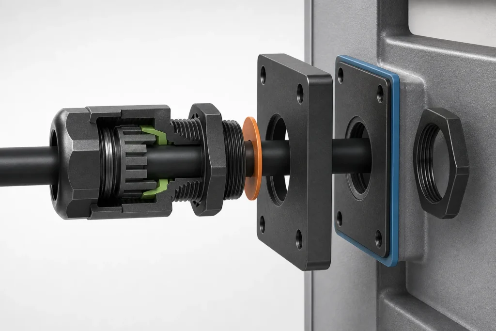
- Cable-to-gland seal: measured cable OD, approved sealing range, jacket condition, and correct assembly.
- Gland-to-plate seal: thread standard, hole size, entry washer or O-ring, locknut engagement, burrs, coating build-up, and local flatness.
- Plate-to-enclosure seal: continuous perimeter gasket, clean gasket land, plate stiffness, fastener spacing, and even compression.
Direct gland entry through the enclosure wall removes the plate perimeter joint. It does not remove the cable-side seal or the gland-to-wall interface. A removable gland plate adds a joint, but it can simplify factory machining, pre-assembly, inspection, and future replacement. Choose the arrangement that controls the actual installation risks with the fewest uncontrolled interfaces.
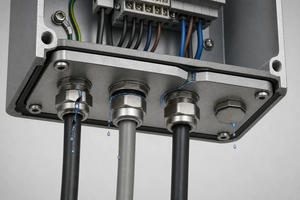
Where water actually gets in
When someone says “the cable gland is leaking,” start with the visible symptom and trace it back to an interface. The wettest point is not always the entry point.
| Possible water path | Common cause | First checks |
|---|---|---|
| Cable jacket to gland seal | Wrong cable OD, damaged or oval jacket, dirt, or incorrect compression | Measure the installed cable, inspect the jacket, confirm the gland range, and follow the manufacturer’s assembly instructions |
| Gland body to plate | Missing entry seal, wrong thread combination, rough hole, poor locknut engagement, or uneven surface | Check thread, hole size, plate thickness, washer or O-ring, locknut, burrs, coating build-up, and local flatness |
| Gland plate perimeter | Twisted plate, thin unsupported sheet, damaged gasket, wide fastener spacing, or uneven tightening | Look for gasket continuity, compression witness, gaps, debris, bowed corners, and plate movement |
| Unused opening | Tape, an unsealed knockout, the wrong blanking plug, or an unapproved insert | Inspect every hole, plug, reducer, adapter, and future cable position |
| Along the cable route | Water runs down the cable, the cable is unsupported, or the route points water at the entry | Check entry direction, drip loop, support, upstream termination, jacket damage, and the moisture track |
| Not an external leak | Condensation forms when humid internal air meets a surface below its dew point | Check temperature cycles, humidity, heat sources, ventilation, drainage, and where droplets first appear |
Gland Plate, Cable Entry Plate, and Cable Entry Gland: What Is the Difference?
Supplier terminology overlaps, so confirm what the quote actually includes. A quote for a panel is not automatically a quote for the glands, modules, blanking parts, or complete cable entry plate sealing assembly.
- Gland plate: usually a removable metal panel fitted to the enclosure.
- Cable entry plate: may mean the metal panel, or a dedicated sealing plate or membrane system that brings several cables through one opening.
- Cable entry gland: the individual fitting that seals around one cable.
- Cable entry seal: a ring, membrane, module, or insert that creates the seal around the cable or the plate.
When comparing a gland plate with a cable entry plate, ask whether the price covers the panel, the sealing modules, the individual glands, the blanking parts, or the complete assembled entry system. “Number of holes” is not a sealing specification.
Five cases that clarify the water-ingress problem
These cases map the Three-Seal Cable Entry Check to five different design risks. They are not interchangeable proof of product performance.
| Case | What it clarifies | Evidence type |
|---|---|---|
| Deepwater Pontus | Entry orientation can create a water-retention path | Public BSEE investigation |
| Thunder Horse | Blank positions remain part of the installed boundary | Public BSEE safety alert |
| Getworks modular data center | Water and humidity barriers may need to be reviewed together | Supplier-published case |
| TenneT and Qirion transformer stations | Below-grade entries involve more than a seal | Supplier-published case |
| Austrian railway tunnel | One entry may be a multi-hazard boundary | Supplier-published case |
Evidence boundary: The Deepwater Pontus and Thunder Horse examples come from public BSEE records. The Getworks, TenneT/Qirion, and Austrian railway examples are supplier-published application pages. None is an FN Enclosure project. They are included to explain design questions, not to make universal performance claims.
1. Deepwater Pontus: a top-mounted gland created a corrosion path
A BSEE investigation found that an encoder on the Deepwater Pontus had a signal cable entering through a gland on top of the vertically mounted unit. Water could settle at the entry, penetrate the encoder over time, and contribute to corrosion at the connection points. The encoder pinion and shaft assembly later failed during normal crane travel.
Entry orientation changed the exposure: water could remain at the seal instead of draining away. BSEE noted that a side-mounted gland might have prevented penetration. That does not mean every top entry will fail; it means a top entry needs an explicit plan for routing, shielding, support, drainage, and sealing. Read the BSEE investigation report.
2. Thunder Horse: blank positions remain part of the boundary
After Hurricane Dennis, BSEE reported multiple failed cable transits at the Thunder Horse facility. The safety alert was preliminary and did not identify one definitive root cause. It recommended checking each transit configuration, installation method, and pressure rating.
The alert concerned cable transits, not a conventional gland plate. The transferable point is narrower: blank blocks, spare holes, and future positions still belong to the installed sealing boundary. Specify and inspect them with the same care as active entries. Read BSEE Safety Alert No. 235.
3. Getworks modular data center: water and humidity were one entry problem
Getworks used pipe seals for cooling-water penetrations in a modular data center in Echigo-Yuzawa, Japan. The published requirements included watertightness, airtightness, a humidity barrier, and resistance to outdoor exposure such as snow and direct sunlight.
For an outdoor enclosure or container, do not review the penetration in isolation. Check humidity control, temperature stability, routing, and the path by which rain or meltwater reaches the wall. This is a supplier-published application example, not independent validation. Read the Getworks case.
4. TenneT and Qirion transformer stations: below-grade entries need more than a seal
A supplier-published case for underground transformer-station entries in the Netherlands lists watertightness, rodent protection, EMI protection, and cable retention as simultaneous requirements. Flooding, humidity, and dust were also part of the risk context.
A below-grade entry should therefore be reviewed with the foundation penetration, surrounding structure, cable retention, sealing modules, drainage, and maintenance access. Checking only the visible cap or compression nut is too narrow. Read the TenneT and Qirion case.
5. Austrian railway tunnel: one entry can be a multi-hazard boundary
A supplier-published railway tunnel case in Austria lists watertightness, EI90 fire protection, and rodent resistance for cable and pipe penetrations. The application also identifies humidity, flooding, and pests as infrastructure risks.
The specification question is not only whether the entry is waterproof. Define every hazard the complete assembly must control, then specify the cable range, wall or plate interface, accessories, installation method, and required evidence. Read the Austrian railway-tunnel case.
Eight details that decide whether the entry stays dry
1. The gland size is not the cable size
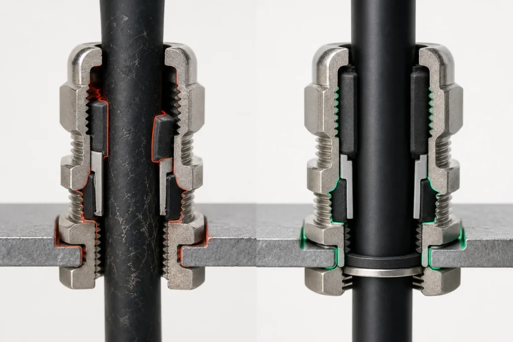
An M25 or M32 label usually identifies the entry thread. It does not tell you the cable sealing range. Two M25 glands can accept different cable diameters, and two cables with the same conductor size can have different jacket diameters.
Measure the actual outside diameter of the cable that will be installed. Match that measurement to the gland manufacturer’s published sealing range. For armored, braided, screened, layered, or pre-terminated cables, also confirm the internal dimensions and assembly sequence required by the gland design. Do not tighten by a universal number of turns. Use the instructions for that gland and that cable combination. See the CMP outer-seal tightening guide.
Wrapping tape around an undersized cable to make it “fit” is not a controlled sealing method unless the selected product documentation specifically permits it.
2. The cable jacket must be a usable sealing surface
The seal needs a clean, continuous jacket. Deep scratches, molded ribs, debris, paint, oil, damaged braid, or an out-of-round cable can leave a channel under the seal. The gland may feel tight while water still has a path.
Inspect the jacket before assembly. Keep the sealing ring away from damaged sections, transitions, printed build-up, and sharp bends. Clean the jacket with a method compatible with the cable material. Do not expose the sealing parts to dirt, solvents, or foreign material. Follow the manufacturer’s cable-gland installation guidance.
3. The entry thread is a separate sealing interface
Checking the gland cap checks only the cable-side seal. Water can also pass between the gland body and the gland plate.
Parallel threads and clearance holes may require a sealing washer or O-ring. Tapered-thread arrangements follow different instructions. Confirm the thread standard, hole size, thread length, plate thickness, locknut arrangement, approved sealing accessory, and entry orientation before drilling. A gland that fits the hole mechanically may still be wrong for the intended sealing method. See the CMP guidance on maintaining ingress protection at cable entries.
4. Gland plate flatness is a functional requirement
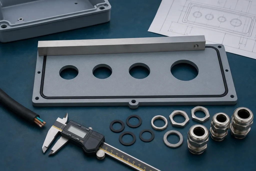
A removable gland plate is a gasketed joint. It needs a flat mating surface and enough stiffness to keep gasket compression even after the cables are installed.
If the plate bows between fasteners, the gasket pressure drops in the unsupported span. A thin plate can distort further when heavy glands or cable bundles apply load. Review these drawing details before fabrication:
- plate material and thickness;
- unsupported span and expected cable load;
- gasket type, width, joint, and compression area;
- fastener quantity, spacing, and tightening sequence;
- tool clearance around glands and locknuts;
- edge distance between holes, gasket land, and fasteners.
Outdoor enclosure guidance from ABB treats the gland plate as a gasketed joint held by a defined fastener arrangement. The same compression logic applies when you review foam gasket compression and sealing on the enclosure side. That is the right way to review it: the gasket can only seal what the plate and enclosure surfaces allow it to seal.
5. Hole quality can damage the seal and the coating
A punched or drilled hole should be round, correctly sized, deburred, and locally flat. A burr can cut a washer, stop the gland shoulder from sitting flat, or damage the cable during installation. A rough field cut can also remove protective coating and create a corrosion point.
After machining, remove chips, deburr both sides, clean the sealing land, and restore the required corrosion protection without leaving a thick paint ridge under the washer. If a hole is added after finishing, define the repair method in the work instruction. Do not leave it to an improvised touch-up during final assembly.
6. Cable routing changes the load on the seal
A cable gland is not a structural bracket for a long, heavy cable run. A hanging cable, sideways pull, or tight bend immediately outside the enclosure can keep the gland, seal, and plate under constant load.
Support the cable independently. Respect its bend radius and leave enough straight length for the gland to seal around an undistorted jacket. For outdoor routing, a downward approach or drip loop can reduce the water delivered directly to the entry. If top entry is unavoidable, review the shield, route, support, drainage, and exact sealing method. Do not rely on the gland label alone.
7. Spare holes are part of the protection system
A spare hole is not neutral. It is an unfinished entry until it has an approved blanking plug, insert, module, or other specified closure.
Specify blanking plugs, reducers, adapters, and spare inserts with the same care as active glands. Record which positions are temporary and which are permanent. If commissioning changes a spare opening, review the replacement component and installation method again. The Thunder Horse safety alert concerned cable transits rather than a conventional gland plate, but the transferable point is clear: blank positions remain part of the installed sealing configuration.
8. Condensation can look exactly like a failed gland
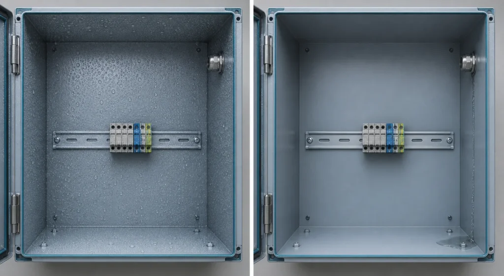
Water at the bottom of an enclosure does not prove that rain entered through the bottom gland plate. Warm, humid air can condense on a cooler roof, door, component, or cable surface and then run to the lowest point. Temperature difference and humidity are basic conditions for condensation inside enclosures. Treat condensation as a separate diagnostic path rather than assuming every wet enclosure has an external leak.
Before replacing every gland, ask:
- Did the moisture appear after rain, washdown, or a rapid nighttime temperature drop”
- Are droplets visible high in the enclosure, or only around one entry”
- Does an internal heat source cycle on and off”
- Can humid air enter through a door opening, conduit, breathing path, or cable route”
- Does staining or a track lead back to one seam”
Direct cable entry or a removable gland plate?
Neither option is automatically better. Choose the arrangement that meets the cable count, layout, service, and fabrication requirements with the fewest uncontrolled interfaces.
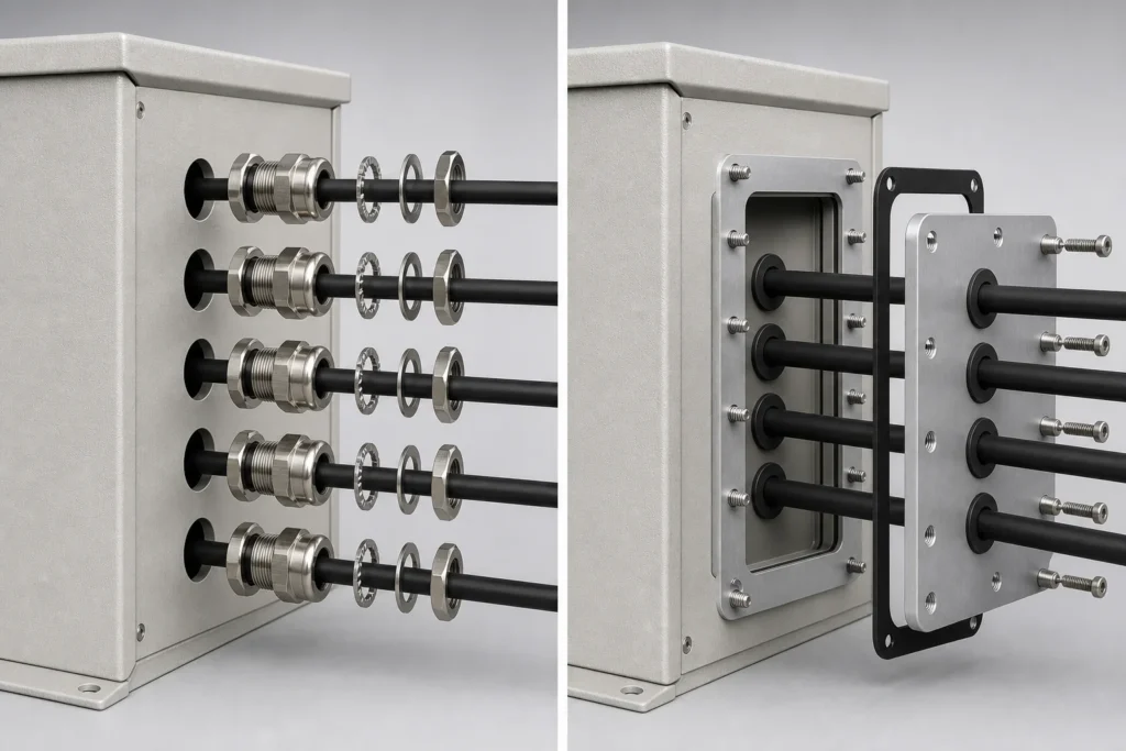
| Option | Useful when | Main sealing benefit | Risk to control |
|---|---|---|---|
| Direct entry through the enclosure wall | Cable quantity and layout are stable, and machining access is good | No separate gland-plate perimeter joint | Harder to modify; field drilling can damage the finish; wall thickness and tool access may limit installation |
| Removable gland plate | There are many entries, changing cable schedules, factory pre-assembly, or replaceable layouts | The panel can be machined, inspected, and replaced separately | Adds a gasketed perimeter seam; plate stiffness, fastener spacing, and cable loads become critical |
| Modular cable-entry system | Cables are pre-terminated, mixed in size, or changed frequently | Several cables can pass through one coordinated system | The frame, modules, compression method, cable range, materials, and installation instructions must work together |
A practical design and installation workflow
Start with the cable schedule, not the hole schedule
List the cable type, actual OD, armor or braid, connector head, bend radius, weight, entry direction, and future spare capacity. Select the gland or cable-entry system after those constraints are known.
Define every sealing interface on the drawing
Show the thread type, hole size, plate thickness, locknut, entry washer or O-ring, gasket land, fastener pattern, and any drain, shield, hood, or drip-loop requirement. “Seal as required” is not an installation instruction.
Protect flatness and finish during fabrication
Control plate distortion, deburr holes, remove chips, protect the gasket surface, and repair coating or passivation as required for the material and environment.
Install one gland system as one system
Use the specified accessories and tightening method. Do not mix parts from different gland systems unless the documentation approves the combination. Support cables before they apply side load or weight to the entry.
Inspect the complete installed assembly
Check every active and spare opening, gasket continuity, plate seating, cable support, and visible compression. If the project requires water-ingress verification, test the actual assembled configuration and record the scope and result.
Rating boundary: a cable gland with a published ingress-protection rating does not automatically give the complete enclosure the same rating. The result depends on the tested product, cable range, entry interface, gland plate joint, unused openings, orientation, installation, and final assembly. IEC 60529 addresses enclosure degrees of protection, while IEC 62444 addresses cable glands. They are related standards, not interchangeable proof of a complete enclosure rating. See IEC 60529 and IEC 62444.
How to troubleshoot water ingress without replacing everything
Start with the moisture pattern. Water often travels before it becomes visible, so the wettest point may not be the entry point. If the enclosure is heated, cooled, or ventilated, review the broader electrical enclosure cooling and condensation control context before replacing entry hardware.
| What you see | Inspect first |
|---|---|
| A wet ring around one cable | Cable OD, jacket condition, sealing range, assembly, and side load |
| Moisture around the locknut or gland body | Washer or O-ring, thread, hole, plate thickness, burrs, and local flatness |
| A water line along the plate edge | Perimeter gasket, plate distortion, fastener spacing, debris, and compression |
| Moisture after cold nights but not after rain | Temperature cycle, humidity, internal heat sources, and condensation pattern |
| Water returns after one entry is resealed | Upstream cable route, spare openings, plate perimeter, and other enclosure seams |
Do not tighten everything harder. Over-tightening can damage seals, deform cable jackets, strip threads, or bend a thin plate. Find the path, check the component instructions, and correct the failed interface.
The 60-Second Cable-Entry Review
Use this check before drilling, before tightening, after rain or washdown, after a cold night, during commissioning, and before issuing an RFQ.
- Measure the actual cable OD.
- Match it to the published gland or module sealing range.
- Check cable-to-gland, gland-to-plate, and plate-to-enclosure interfaces.
- Inspect plate flatness, gasket continuity, and fastener compression.
- Check every spare hole, blank, reducer, adapter, and future position.
- Separate external leakage from condensation.
What to include in a gland plate or cable entry plate RFQ
Send enough information to match the panel, entry system, and installation environment, not just the number of holes. A complete RFQ lets the supplier review the cable entry plate sealing approach before fabrication.
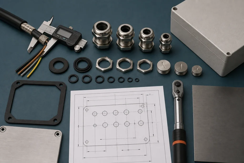
- Cable schedule with actual outer diameters, not only conductor sizes
- Cable construction: unarmored, armored, braided, screened, or pre-terminated
- Selected gland models, sealing ranges, and entry thread types
- Required entry direction and installation orientation
- Gland plate drawing, material, thickness, hole locations, and spare openings
- Required enclosure protection target and applicable project standard
- Outdoor, washdown, coastal, chemical, UV, temperature, or vibration exposure
- Cable support, bend radius, drip loop, shield, or hood requirements
- Approved plugs, reducers, adapters, washers, and O-rings
- Inspection, test, photo, and document requirements for the assembled entry system
If these details are missing, the supplier has to guess. The hole pattern may match the drawing while the sealing method fails to match the cable and the field installation. Review the cable entry plate sealing approach before fabrication, not after a leak appears.
The takeaway
Do not treat cable glands, gland plates, cable entry plates, and blanking parts as accessories added after the enclosure is designed. They are part of the enclosure’s water-ingress control system.
The useful question is not “Is this cable gland waterproof?” Ask instead: Which interface seals the cable, the gland entry, the plate perimeter, and every spare opening in the final installed configuration?
Preparing a custom gland plate or cable-entry layout?
Send the cable schedule, actual cable diameters, entry layout, material, installation environment, and protection target. If you are planning a custom electrical enclosure, include the proposed sealing method and spare-opening plan so the interfaces can be reviewed before the holes are cut.
Frequently asked questions
Does an IP68 cable gland make the whole enclosure IP68?
No. The complete enclosure still depends on the cable-to-gland seal, the gland-to-wall or gland-to-plate interface, the gland plate perimeter when one is used, every unused opening, the orientation, and the installation method. Evaluate the final assembly against the project requirement.
Is a removable gland plate more likely to leak than a direct cable entry?
Not automatically. A gland plate can meet the required protection target when the plate is rigid and flat, the perimeter gasket is continuous, fastener pressure is even, and every cable entry is sealed correctly. It does add one more joint to design and inspect.
Should outdoor cables always enter through the bottom of the enclosure?
Bottom or downward-facing entry often reduces direct water exposure, but it is not a universal rule. Cable bend radius, drainage, maintenance access, internal layout, installation orientation, and project requirements still matter.
Can silicone sealant replace a cable gland sealing washer?
Do not assume it can. A field-applied sealant may hide a poor interface, interfere with service, or be incompatible with the materials. Use the sealing method and accessories specified by the cable gland manufacturer and project documentation.
Why is there water inside an enclosure when the cable glands look dry?
The moisture may be condensation, water running along a cable, leakage at an unused opening, or a gland plate perimeter leak that travels before becoming visible. Check the moisture pattern and environmental conditions before replacing parts.
What information should be included in a gland plate RFQ?
Include the cable schedule with actual outer diameters, cable construction, gland models or thread types, entry direction, plate drawing and material, protection target, environment, spare-opening plan, cable support requirements, approved accessories, and any required inspection or test documentation.