

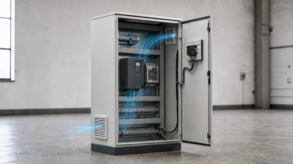
Electrical enclosure filter fans draw outside air through a filter and discharge warmer air through an outlet. Selecting one starts with the cabinet heat load and the temperature of the surrounding air, then moves to the resistance of the installed path and the enclosure openings.
If the cabinet stays hot, the outlet flow is weak, the filter is loading, or water appears near the opening, start with the commissioning, maintenance, and finished-configuration sections. A running fan does not identify the cause by itself.
Can a filter fan work in your enclosure?
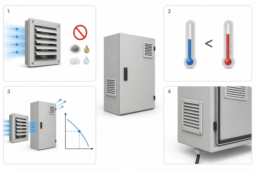
Check these four conditions before selecting a frame size. Stop and revise the design wherever a condition cannot be met.
| Check | Question | Stop condition |
|---|---|---|
| Air allowed? | Can ambient air enter without creating an unacceptable dust, oil, salt, moisture, or corrosion risk? | The cabinet must remain sealed, or the air cannot be admitted. |
| Ambient lower? | Is maximum ambient temperature below the maximum allowable cabinet temperature? | Ambient temperature is equal to or hotter than the target. |
| Airflow proven? | Will the selected fan deliver the required airflow at the resistance of the installed path? | Selection uses only free-air CFM or enclosure volume. |
| Assembly acceptable? | Can the cutout, gasket, outlet, orientation, controls, rating evidence, and filter access be verified? | The finished configuration or maintenance plan is undefined. |
The last check matters in production. A filter behind a machine, above a guarded platform, or against a wall may be technically replaceable and still be ignored. Access, replacement media, and a first inspection trigger belong in the design.
A filter fan cannot cool a cabinet below the surrounding air temperature. If the maximum ambient is 42°C and the cabinet limit is 40°C, ventilation cannot meet that limit. Reduce the heat load, lower the ambient, raise the allowable internal temperature where the equipment permits it, or choose a cooling method that can meet the temperature requirement. A closed-loop air-to-air exchanger still needs cooler ambient air; it will not solve a below-ambient requirement.
Calculate the airflow requirement
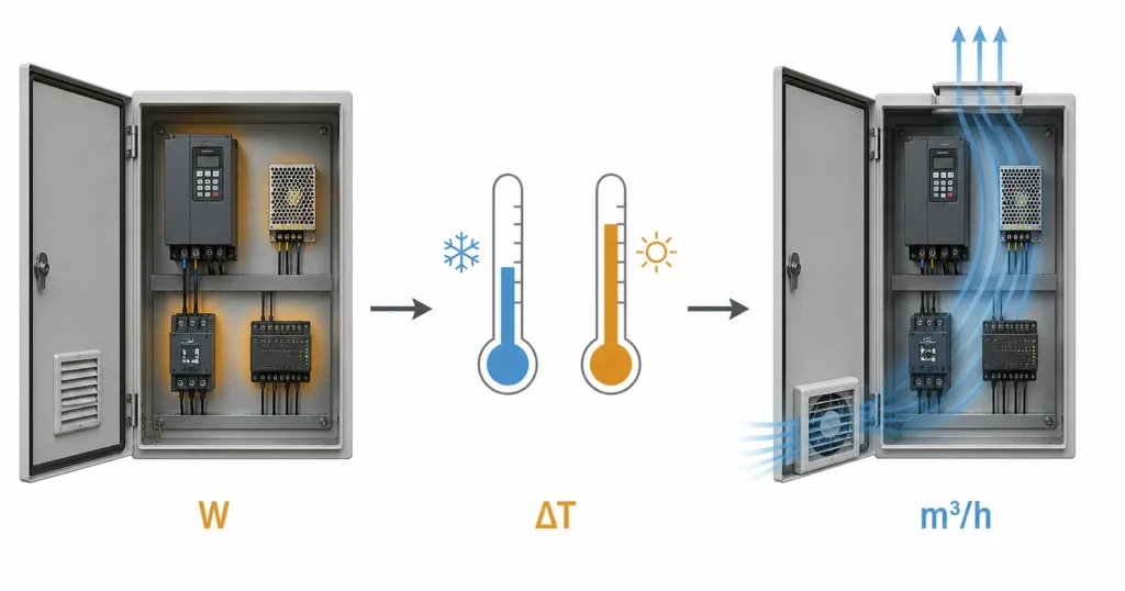
Start with the heat released inside the enclosure and the allowable temperature rise. Do not size the fan from enclosure volume or from the equipment input rating alone.
A 7.5 kW drive does not necessarily release 7.5 kW into the cabinet. Use the manufacturer’s heat-loss data at the expected load. Add losses from drives, power supplies, PLCs, relays, transformers, contactors, braking resistors, communication equipment, and other internal devices. Subtract heat deliberately rejected outside the enclosure.
The basic relationship is:
P = ρ × cp × q × ΔT
For a practical sea-level estimate using watts and degrees Celsius:
Required airflow, m³/h ≈ 3.1 × internal heat loss in W ÷ allowable temperature rise in K
To convert m³/h to CFM, multiply by approximately 0.5886.
Worked example
| Input or result | Value |
|---|---|
| Internal heat loss | 104 W |
| Maximum ambient temperature | 30°C |
| Maximum target enclosure temperature | 45°C |
| Allowable temperature rise | 15 K |
| Minimum calculated airflow | 3.1 × 10⁴ ÷ 15 = 21.5 m³/h |
| Approximate CFM | 21.5 × 0.5886 = 12.7 CFM |
The supplier sizing example uses these same inputs and results. The calculation gives a minimum heat-removal airflow under simplified conditions. It does not select a fan. The selected unit must still deliver at least 21.5 m³/h after the intake filter, grille, internal path, outlet, hood, and expected contamination add resistance.
Before releasing the fan selection, record the following separately:
- Heat-loss inputs and load assumptions.
- The calculated minimum airflow.
- The pressure losses that still need supplier data.
- The installed working point under clean and loaded filter conditions.
- The closed-door commissioning result.
Altitude reduces air density. Solar gain, recirculated exhaust, nearby equipment, load cycling, and a higher-than-estimated heat loss can also move the design point. State these conditions in the calculation instead of hiding them inside an unexplained safety factor. An electrical enclosure sizing guide can help organize heat load, clearances, mounting space, and future expansion before openings are released.
Check the installed operating point
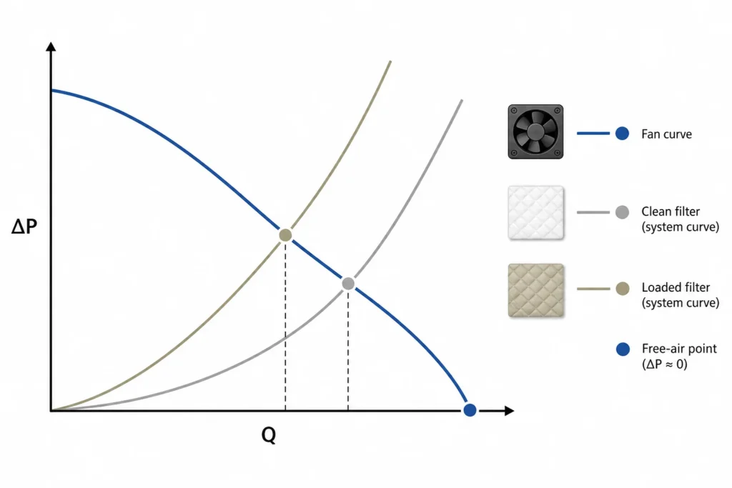
Free-air airflow is a catalog condition. Installed airflow is the result of the fan curve and the enclosure system curve.
The installed path can include filter media, a finger guard, louver, rain hood, narrow outlet, cable duct, wiring bundle, partition, and a loaded filter. The fan curve shows available pressure at different flow rates. The system curve shows the pressure required by the path. Their intersection is the operating point.
Use this sequence:
- Calculate the minimum thermal airflow.
- Map every restriction from intake to exhaust.
- Obtain the fan curve for the intended voltage, frequency, direction, and filter.
- Obtain pressure-loss data for the matching outlet and any hood.
- Find the clean-filter operating point.
- Check a realistic loaded-filter condition.
- Confirm that both conditions remain above the thermal requirement.
- Measure the finished cabinet during commissioning.
A supplier page that lists one airflow number without a pressure curve leaves the selection unfinished. Ask for the curve, test configuration, filter condition, voltage, frequency, airflow direction, and matching outlet data. ISO 5801 provides standardized fan performance testing, while AMCA Publication 201 discusses system effects. Test data still has to be applied to the actual enclosure path.
Compare documented fan configurations
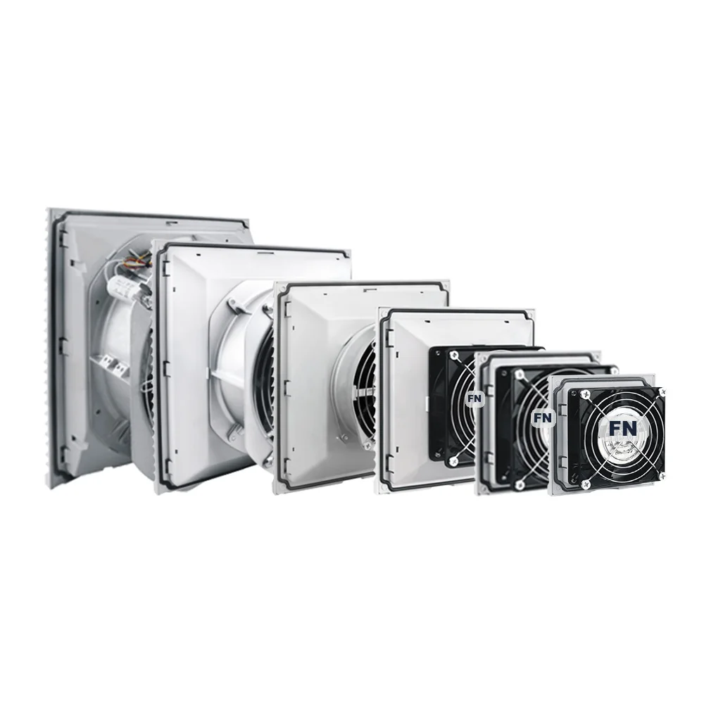
For each candidate, keep the supplier data together so the airflow, outlet, cutout, and rating refer to the same configuration.
| Item to compare | Information to obtain |
|---|---|
| Source | Supplier name, document title, revision, and authorized data-sheet access |
| Exact configuration | Family and order code, voltage, frequency, airflow direction, filter media, and matching outlet |
| Airflow | Fan or assembly curve, test configuration, static pressure, and clean or loaded filter condition |
| Opening | Approved cutout drawing, tolerance, panel thickness, mounting method, and service clearance |
| Protection | Applicable standard and evidence covering the selected parts, orientation, gasket, retention, and hood |
Resolve differences between a bare-fan sheet and a filter-fan assembly sheet with the supplier. Values from different configurations cannot establish the pressure loss of the selected filter. Record the approved order code and document revision on the enclosure drawing before fabrication. Third-party model data does not establish FN production, stock, or supply scope.
Supplier application example: a photovoltaic plant
A Pfannenberg application page reports an outdoor filter fan rated at 505 m³/h and IP55 for a 50 MW photovoltaic plant in the Philippines. That is supplier-published application information. It does not independently establish the cabinet temperature, the installed airflow, long-term field performance, or the rating of another finished enclosure.
Use application pages to identify questions for the project. Confirm the actual fan order code, test conditions, openings, exposure, and acceptance criteria before applying the information to a new cabinet.
Plan the inlet, outlet, and cutouts
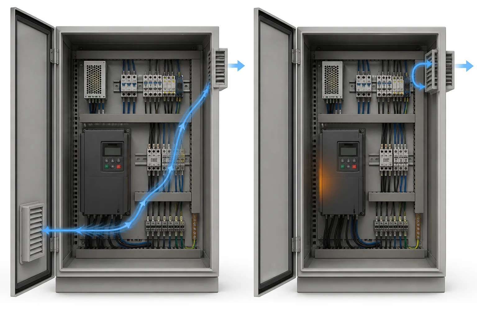
A low filtered intake and a high passive outlet are a useful starting layout because they can move air across the cabinet. The heat map decides the final positions.
Draw the air path on the enclosure layout before approving the cutouts:
- Mark major heat sources and temperature-sensitive devices.
- Trace air from the filter face to the outlet.
- Check cable ducts, wire bundles, shelves, mounting plates, and partitions.
- Move an opening if air can bypass the heat sources.
- Keep discharged hot air away from the intake.
- Reserve external clearance for filter removal.
A powered intake can create slight positive pressure when seams and penetrations are controlled. The outlet still needs enough area to avoid choking the fan. Door-mounted fans add moving wiring, weight, hinge load, and service-clearance constraints.
Outdoor top outlets and horizontal openings need a separate water review. A hood can reduce direct exposure and also change pressure loss. Fan openings are only one part of the boundary. Cable entries, gland plates, drains, locks, seams, and door seals can provide other air or water paths. See the guide to cable glands, gland plates, and water ingress when the opening is part of a wider penetration plan.
Check the finished protection boundary
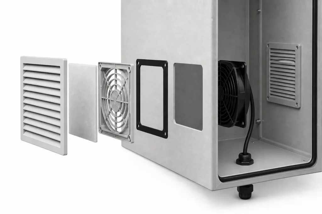
The filter fan, gasket, cutout, outlet, door seal, cable entry, and other penetrations form one finished configuration. A rating printed on a component does not automatically transfer to the enclosure.
Request the applicable standard and report scope for the selected fan and outlet. Confirm the covered order codes, mounting direction, filter, gasket, retention method, and any hood used in the tested configuration.
IEC 60529 defines the IP Code. NEMA enclosure Types cover a different set of construction and environmental requirements. NEMA’s enclosure Types guidance states that IEC IP designations should not be used as substitutes for NEMA Type ratings in U.S. installations. A one-to-one conversion table is not compliance evidence.
Check these interfaces against the approved drawing. For the door seal, the foam gasket guide explains how compression and aging affect contact around the perimeter:
| Interface | What to inspect |
|---|---|
| Cutout | Size, corner shape, burrs, distortion, and exposed metal that could prevent a flat seal |
| Gasket | Folds, twists, dirt, damage, and uneven compression |
| Orientation | Louver direction and any vertical-only mounting requirement |
| Retention | Clips, screws, and even fastener load |
| Outlet | Rating, open area, and pressure loss |
| Hood | Water shielding and the change to the tested configuration and operating point |
| Other penetrations | Cable glands, drains, locks, seams, and door seals |
A Fandis IP test-chamber article describes defined water-flow and nozzle conditions for IPX4 and IPX5 testing. Such values describe a test condition. They are not a general waterproof claim. For the enclosure-level decision, see the IP65 vs IP66 electrical enclosure guide.
Control the cutout and installation
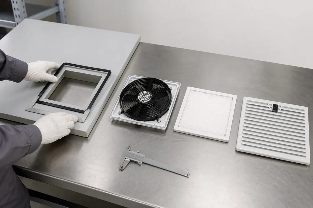
Use the approved component drawing to set the cutout size, tolerance, corner radii, panel thickness, and mounting method. A frame size alone does not define the opening.
Before fabrication:
- Record the family, order code, voltage, frequency, and document revision.
- Use the approved cutout drawing and tolerance.
- Confirm panel thickness and mounting method.
- Check stiffeners, flanges, rails, ducts, latches, and internal equipment.
- Confirm that the opening will not weaken the door or interfere with seal compression.
- Reserve space to remove the filter mat.
During fabrication and installation, keep chips and grinding dust away from installed equipment. Arrange internal work with the equipment safely isolated.
- Cut the specified dimensions and corner radii.
- Deburr without rolling or distorting the panel edge.
- Repair damaged coating or exposed metal using the approved process.
- Clean the gasket contact surface.
- Seat the gasket flat and reject folds or contamination.
- Install the fan in the specified direction.
- Engage every clip or fastener evenly.
- Keep wiring away from the blade, hinge, pinch points, and filter service path.
- Fit the matching outlet and any specified hood.
- Close the door and check internal clearance before energizing.
A controlled factory opening is usually more repeatable than an improvised site modification. FN can manufacture custom electrical enclosures around approved fan, filter, louver, and accessory drawings. The drawing should define the size, tolerance, location, orientation, panel thickness, edge treatment, hardware scope, and whether accessories are fitted or supplied loose.
Use controls to manage exposure
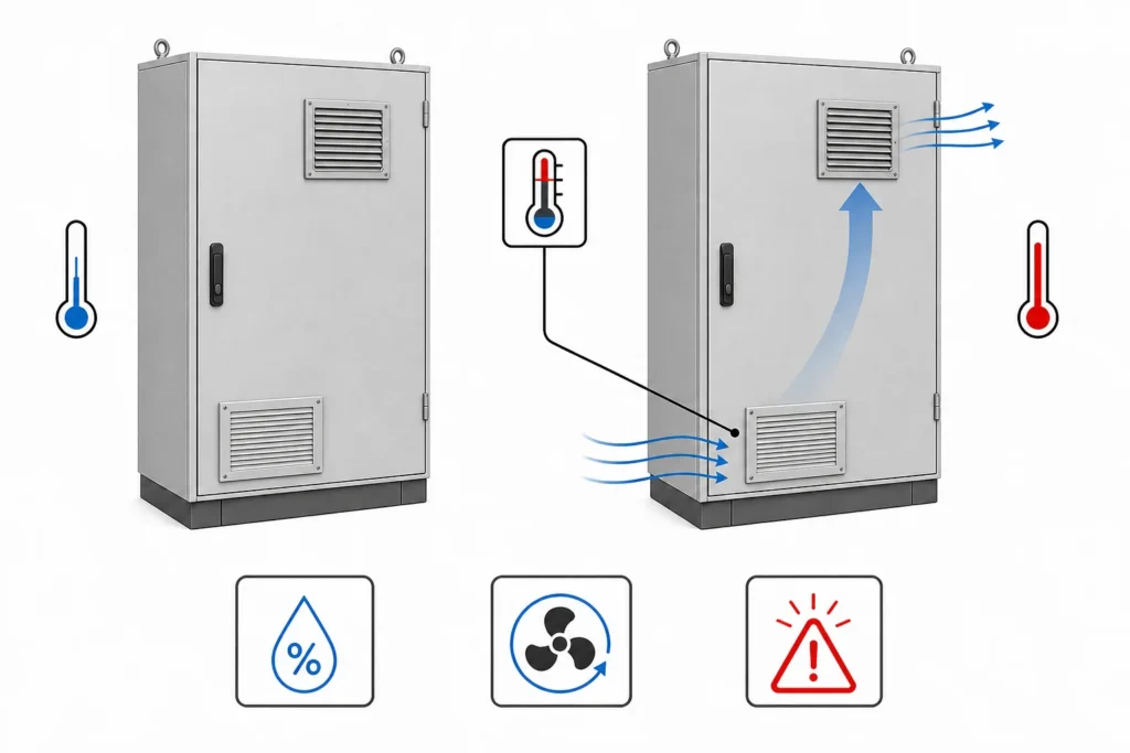
Continuous operation pulls air through the filter whenever power is present. In dusty or humid areas, that can load the media faster or import moisture when cooling is unnecessary.
A thermostat can start the fan above a setpoint and stop it after the defined hysteresis. Place the sensor near the controlled risk rather than in the cool inlet stream. A hygrostat responds to relative humidity, while condensation depends on dew point, surface temperature, humidity, and temperature cycling. A heater, controlled ventilation sequence, dehumidification, or closed-loop method may be needed. Use the enclosure condensation guide to review moisture during operation and shutdown.
Possible monitoring signals include tachometer feedback, low-speed or locked-rotor alarm, differential pressure across the filter, cabinet high-temperature alarm, PWM speed input, 0 to 10 V control, and PLC or network alarm integration. An Orion Fans control overview gives examples, including a 5 V tachometer output, a typical 25 kHz PWM input, and 0 to 10 V proportional control. Check the selected fan data sheet because these signals are not universal.
Define the response to each alarm. It may create a maintenance work order, reduce machine load, start a standby fan, or stop the process. Recording an alarm without assigning an action does not protect the cabinet.
Commission the finished cabinet
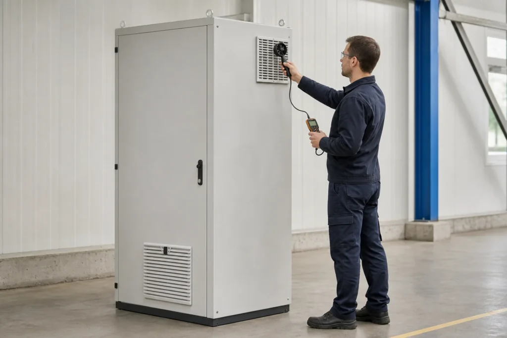
Commission the configuration that will operate in the field, with the filter installed and the door closed.
- Confirm the fan, filter, outlet, hood, voltage, frequency, direction, and protective-device part numbers.
- Close doors, covers, and gland plates.
- Run a representative process load.
- Wait for temperatures to stabilize.
- Record ambient, intake, exhaust, cabinet-air, and critical hotspot temperatures.
- Check for weak flow, recirculation, blocked passages, and direct inlet-to-outlet short circuits.
- Inspect gasket compression, fasteners, coating repair, cable entries, drains, and water shields.
- Test thermostat switching, fan feedback, high-temperature alarm, and PLC response.
- Save a clean-filter baseline.
Define acceptance criteria before the test. Include the maximum hotspot temperature, maximum cabinet-air temperature, minimum airflow or maximum differential pressure, alarm setpoint, operating load, ambient condition, and measurement method.
A useful acceptance record includes:
| Field | Record |
|---|---|
| Fan and filter | Exact installed parts and replacement media |
| Clean-filter baseline | Airflow or differential pressure, instrument, location, and method |
| Ambient | Temperature during commissioning |
| Critical hotspot | Component, location, load, and stabilized temperature |
| Alarm response | Setpoint, delay, hysteresis, and required action |
| Filter trigger | Temperature, pressure, airflow, visual, or alarm condition |
| Review | Commissioning date and reviewer |
Inspect and replace the filter by condition
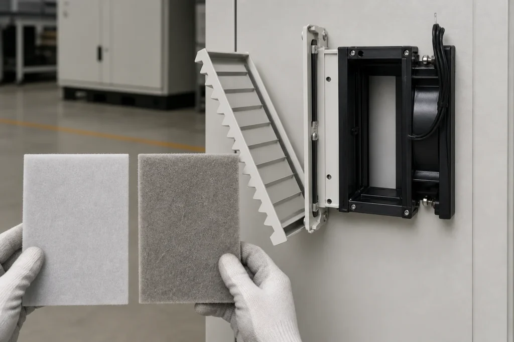
The same filter can remain clean in a control room and load quickly beside a woodworking line or machining cell. Start with a conservative inspection interval based on exposure, then adjust it after site data is available. Do not turn a supplier life claim into a universal replacement interval.
| Symptom | Possible causes to check | Action |
|---|---|---|
| Temperature rises at similar load and ambient | Filter restriction, fan degradation, blocked outlet, or changed airflow path | Compare with the commissioning baseline and inspect the full path. |
| Filter mat is dark, oily, matted, or visibly loaded | Filter restriction; compare airflow or pressure readings with the clean baseline | Replace it, or clean it only if the media manufacturer permits cleaning. |
| Fan runs but outlet flow is weak | Wrong direction, low voltage, damaged fan, dirty media, or excessive resistance | Check rotation, voltage, filter, outlet area, and working point. |
| More dust appears inside | Lost positive pressure, damaged media, poor gasket, or unintended leakage | Inspect the filter fit, gasket, outlet, cable entries, and door seal. |
| Noise or vibration increases | Bearing wear, blade contamination, loose mounting, or obstruction | Isolate safely, then inspect, clean, tighten, or replace. |
| High-temperature alarm repeats | Heat load or ambient rose, control failed, or airflow fell | Recheck the original inputs before fitting a larger fan. |
| Water tracks appear near the opening | Wrong orientation, folded gasket, missing shield, or unsuitable cooling method | Correct the interface and reassess whether open-loop cooling belongs there. |
Do not blow out a filter with compressed air unless the media manufacturer permits it. The air jet can damage fibers, push contamination through the mat, or leave a filter that looks clean but no longer performs as specified.
Record the inspection date, ambient temperature, process load, temperatures, alarm history, filter appearance, airflow or pressure readings, and any replacement part. Compare readings under similar operating conditions.
Choose an alternative cooling method
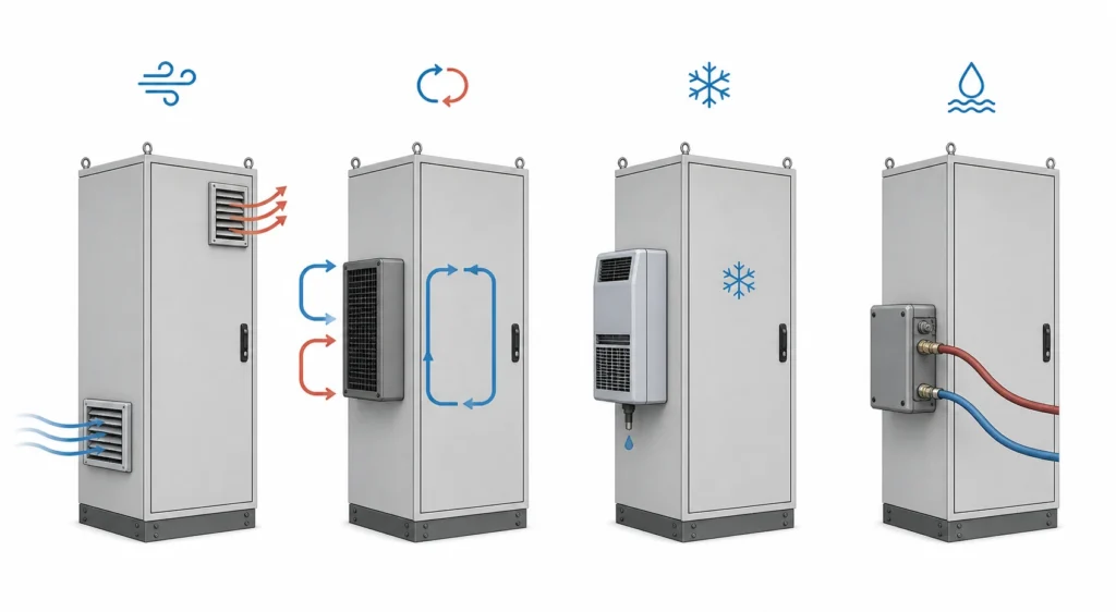
If the initial suitability checks rule out a filter fan, compare methods against the required temperature and the need to keep outside air separate. Select a method with enough capacity under the project conditions.
An air-to-air heat exchanger keeps internal and external air separate, but it still needs cooler ambient air. An enclosure air conditioner can cool below ambient, with added requirements for condensate, refrigeration service, power, and heat rejection. An air-to-water exchanger transfers heat to a water circuit and adds piping, water-quality, leak, and control requirements.
Outdoor cabinets need one combined review of solar load, day and night temperature, rain, drainage, UV, corrosion, cable entry, and service access. The FN outdoor electrical enclosures page covers the enclosure construction side. Thermal performance and environmental evidence still need a project-specific scope.
Send the layout and approved component drawings
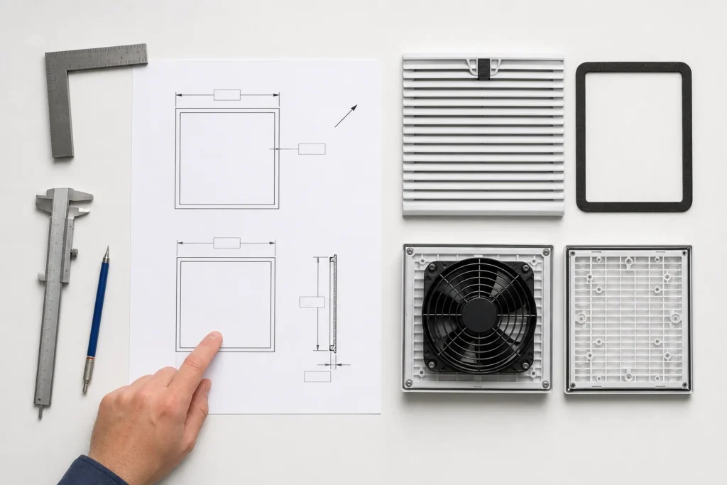
A fan part number is not enough for an enclosure quotation. Send the information that determines the cooling path, protection boundary, and acceptance test.
| RFQ input | Required information |
|---|---|
| Heat loss | Watts released at normal and maximum load |
| Ambient | Minimum and maximum temperature, humidity, altitude, solar exposure, and nearby heat sources |
| Temperature limit | Maximum cabinet-air temperature and critical component limits |
| Contamination | Dust, fibers, oil mist, salt, corrosive vapor, rain, washdown, and cleaning chemicals |
| Protection target | Required IP or NEMA Type and evidence expected for the finished configuration |
| Airflow | Calculated thermal airflow, expected resistance, and clean or loaded filter condition |
| Fan | Exact family and order code, voltage, frequency, current, curve, media, noise limit, direction, and control interface |
| Evidence package | Catalog revision, fan and assembly curves, test configuration, outlet pressure loss, filter condition, report scope, installation drawing, and CAD files |
| Layout | Intake, outlet, heat map, internal obstructions, external clearance, and recirculation risk |
| Fabrication | Cutout drawing, tolerance, panel thickness, corner radii, edge repair, fasteners, and gasket |
| Controls | Thermostat, hygrostat, alarm, PWM, 0 to 10 V, or network interface |
| Maintenance | Access direction, replacement media, inspection trigger, and baseline record |
| Acceptance | Load, ambient, temperature, airflow, pressure, alarm, sealing, and documentation criteria |
For industrial automation enclosures, include the drive layout, heat losses, and service access. For a custom cabinet, send the requirements through FN’s contact page. Confirm whether accessories are factory-fitted, supplied loose, or installed by another party. Assign responsibility for thermal calculations, fan selection, complete-configuration rating evidence, commissioning, and site validation before fabrication.
FAQ
How do I calculate airflow for an electrical enclosure filter fan?
Estimate the heat released inside the cabinet and divide it by the allowable temperature rise: m³/h ≈ 3.1 × watts ÷ temperature rise in K. Then check the selected fan at the resistance of the installed path. The calculated airflow is the thermal minimum for those inputs; the selected unit must deliver it in the installed configuration.
Does an IP-rated filter fan make the complete enclosure the same IP rating?
No. The finished result depends on the fan, outlet, cutout, gasket, orientation, fasteners, hood, cable entries, door seals, and other penetrations. Request evidence for the actual finished configuration.
Should the filter fan be used as an intake or an exhaust?
A filtered powered intake with a high outlet is common because it can create slight positive pressure and reduce unfiltered leakage through gaps. Follow the heat map, avoid a short path between openings, and verify the outlet resistance.
How often should the filter mat be replaced?
Use site condition and the commissioning baseline. Triggers can include higher cabinet temperature at comparable load, lower airflow, higher differential pressure, visible loading, repeated alarms, or more dust inside. A universal calendar interval is not justified without site evidence.
Can a filter fan cool below ambient temperature?
No. It reduces the cabinet temperature rise above ambient. Use an enclosure air conditioner or an air-to-water system supplied with suitable cooling water when the cabinet must operate below ambient.
Why is the cabinet still hot when the fan is running?
Check airflow direction, filter restriction, outlet area, recirculation, blocked internal passages, short-circuit flow, actual heat loss, maximum ambient temperature, supply voltage, and the installed operating point. Rotation alone does not prove useful airflow.
Do thermostat and hygrostat controls prevent condensation?
Not by themselves. Condensation depends on dew point, surface temperature, humidity, and temperature cycling. Ventilation may import moisture. The application may need a heater, controlled sequencing, dehumidification, or closed-loop cooling.
Can I select a fan from one catalog airflow value?
Use a catalog value to screen size and opening only. Final selection requires the exact order code, voltage and frequency, fan or assembly curve, matching outlet resistance, clean and loaded filter conditions, installation path, and a closed-door commissioning check.
What should I send for a filter-fan enclosure quotation?
Send the heat loss, ambient range, cabinet and component temperature limits, contaminants, humidity, altitude, required IP or NEMA Type, fan order code and electrical supply, approved cutout drawing, panel thickness, inlet and outlet layout, controls, and maintenance access. Confirm who supplies the accessories and who is responsible for thermal selection and final validation.