

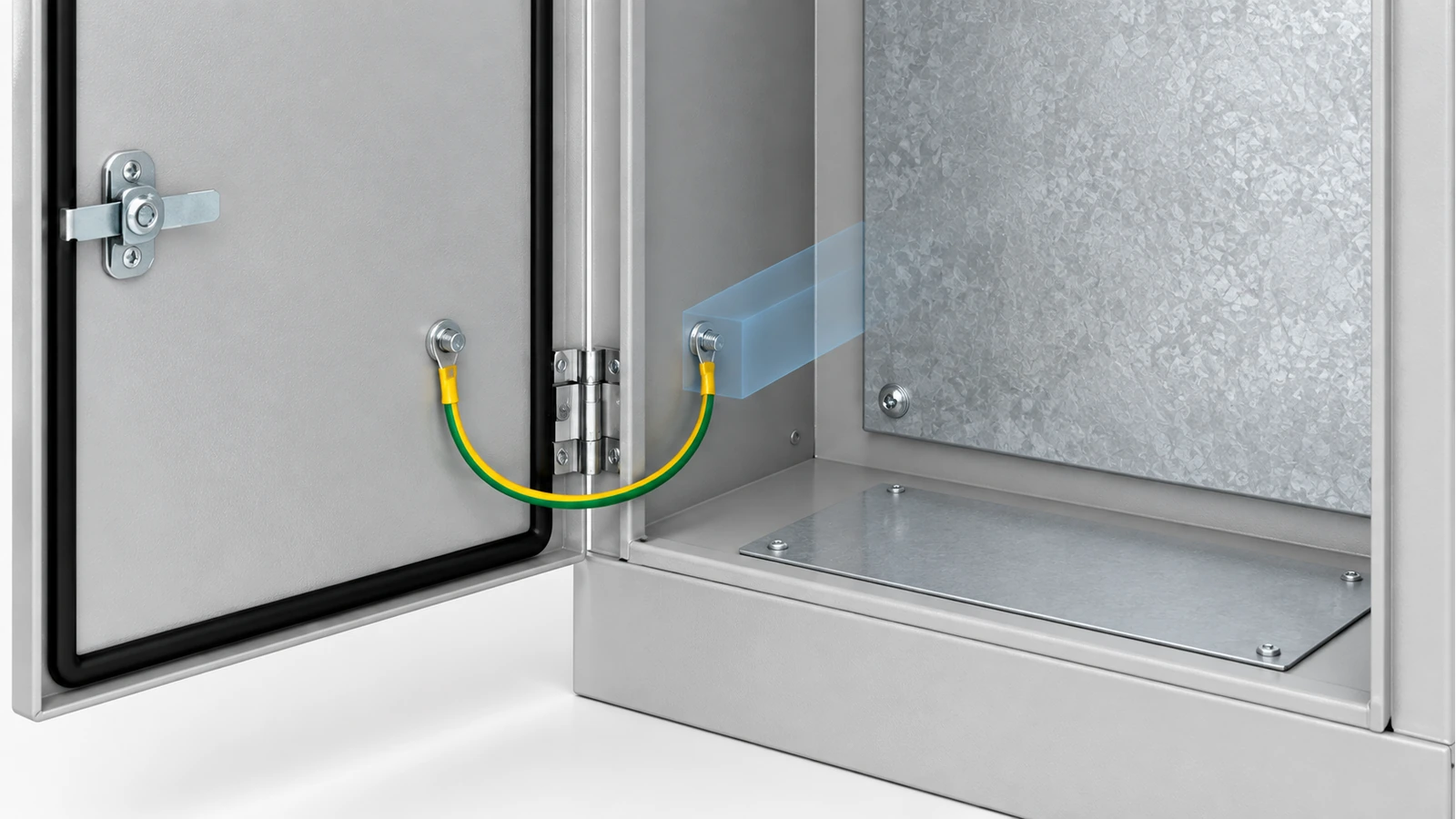
Image note: The illustrations below are AI-generated editorial visualizations based on enclosure product-style references. They are not photographs, project-specific wiring drawings, test records or certification evidence.
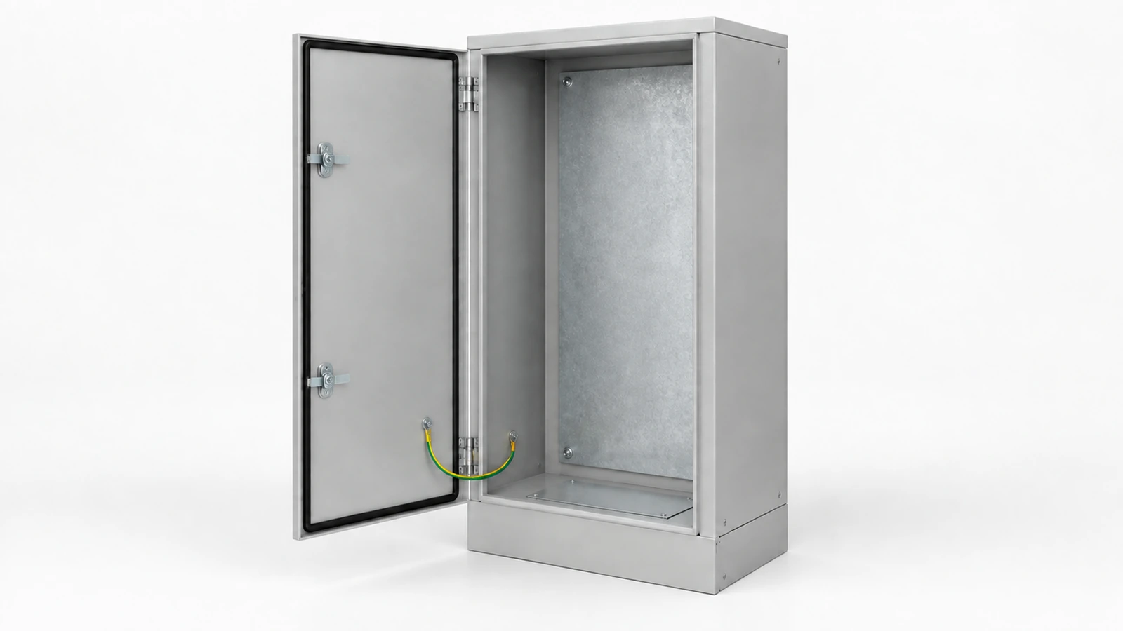
Electrical enclosure grounding needs a continuous, effective protective connection. The cabinet body, door, mounting plate and removable metal parts must be considered in the bonding design; a grounding point on the body does not resolve every interface. Before fabrication, identify the parts that require bonding, define each connection, and agree who will assemble and verify it.
This guide is for enclosure buyers, OEMs and panel builders reviewing a metal cabinet before production. The project electrical designer must confirm the applicable requirements, conductor selection, connection ratings and acceptance criteria. The checks below help define the enclosure supplier’s scope; they do not replace that electrical design.
What grounding and bonding mean for a metal enclosure
Bonding establishes electrical continuity between conductive parts. In the protective arrangement discussed here, those parts connect to the equipment’s protective grounding system. The complete arrangement must provide an effective fault-current path so the protective system can operate as designed. An earth electrode alone does not establish the connections between a cabinet’s separate metal parts.
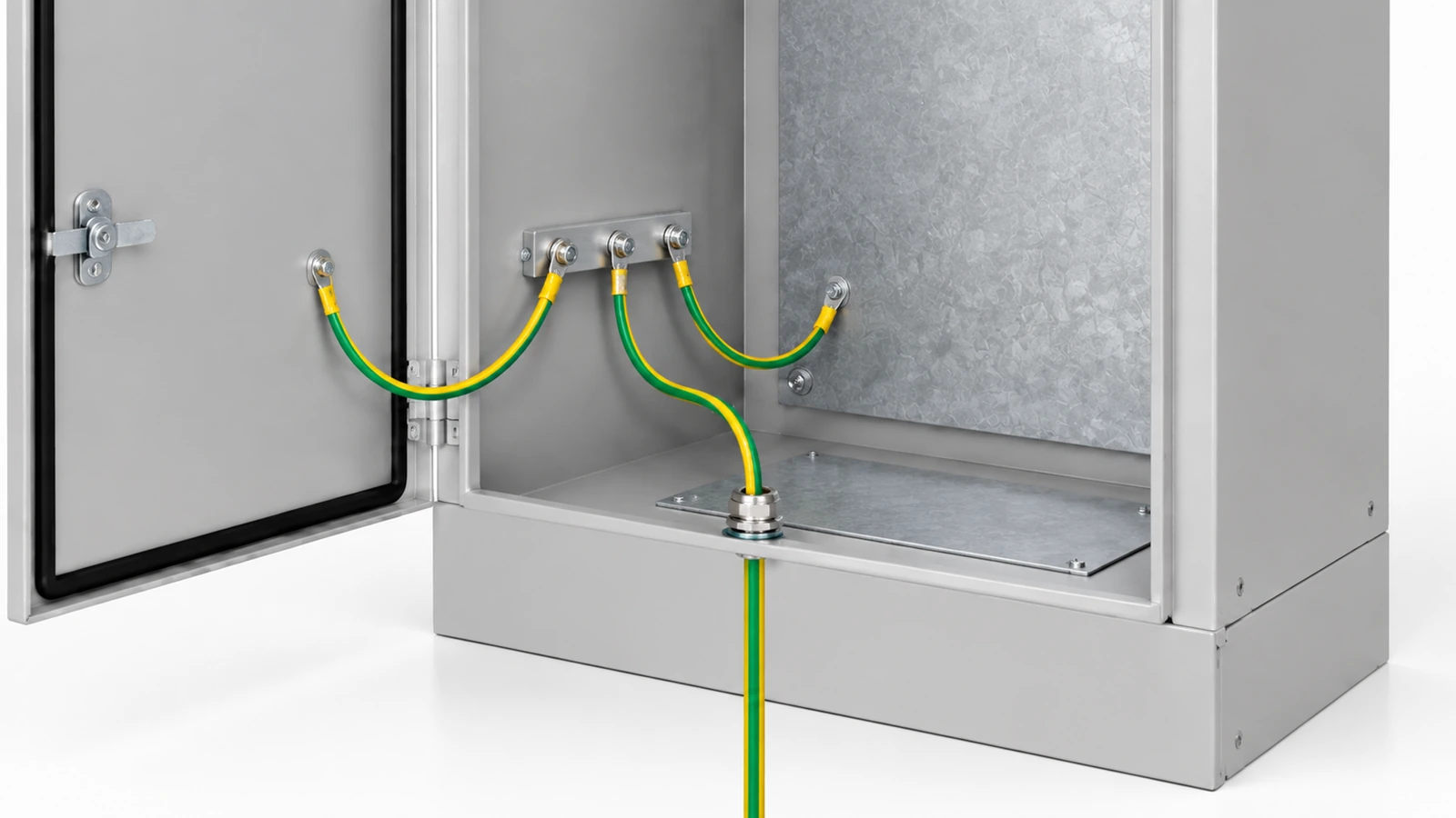
Protective grounding also has a different purpose from functional grounding. Functional grounding may support equipment operation or electromagnetic compatibility (EMC). Schneider Electric makes this distinction in its ULP system guide. A connection intended for noise control should not be assumed to meet a protective-bonding requirement without checking its design.
For an enclosure drawing, the practical questions are:
- Which metal parts are included in the protective circuit?
- What connection joins each part to that circuit?
- What happens to the connection when a door opens or a panel is removed?
- Who is responsible for proving the completed arrangement is acceptable?
Map the enclosure bonding interfaces before fabrication
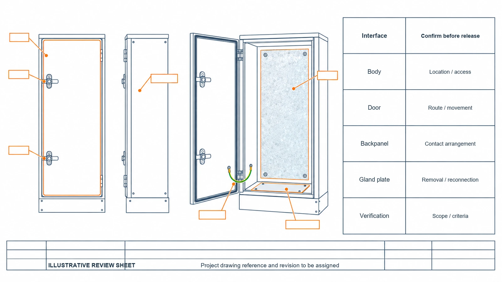
Give each connection a reference on the assembly drawing. The following schedule is a useful starting point for a design review, not a list of mandatory jumper locations.
| Part or interface | Decision to record | Detail to show on the drawing |
|---|---|---|
| Cabinet body or frame | Where the enclosure connects to the project protective circuit | Connection location, approved hardware and access clearance |
| Door | Whether the specified construction provides the required continuity or needs a separate bond | Connection points, jumper route if required, and door travel |
| Mounting plate or backpanel | Whether its fixing system is an accepted bonding path | Contact arrangement and any separate bonding connection |
| Removable cover or side panel | How continuity will be provided and restored after removal | Fasteners or jumper, identification and reassembly requirements |
| Gland plate or cable-entry plate | How the plate and relevant cable-entry hardware join the protective circuit | Bonding interfaces, coating treatment and inspection access |
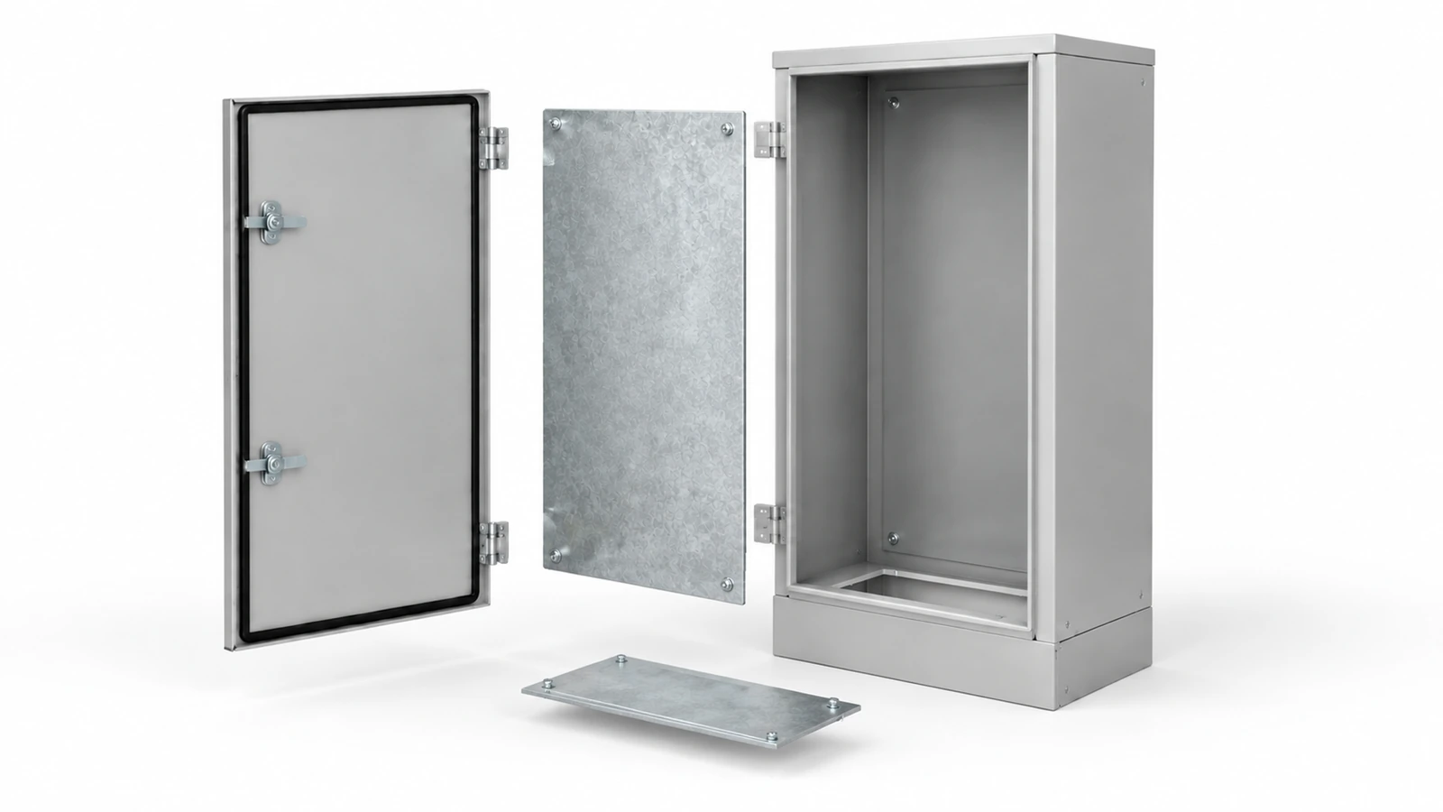
Manufacturer documentation illustrates why these interfaces deserve separate attention. nVent HOFFMAN describes a door-to-body bonding kit, while its INLINE enclosure documentation identifies cover and body bonding provisions. Its grounding accessories sheet separately lists panel-mounting and grounding hardware for CONCEPT enclosures.
These references belong to different product families. They are structural examples, not an interchangeable parts list or evidence that one accessory completes every cabinet’s protective circuit.
Check the body, door and internal metalwork separately
Cabinet body: define the connection and leave access
A drawing note saying “grounding point required” leaves too much for the fabricator to interpret. Show the location, attachment detail, contact surface and identification. Confirm that the proposed connection remains reachable after the mounting plate and equipment are installed.
For a custom cabinet, settle these questions before releasing the sheet-metal drawings:
- Does the supplier provide only the connection provision, or also the terminal and hardware?
- Is the hardware assembled at the factory or supplied loose?
- Can an installer fit and inspect the specified termination without removing unrelated equipment?
- Who approves a location change if the electrical layout changes?
Keep the approved electrical connection detail tied to the fabrication drawing revision.
Door: review movement as well as electrical continuity
Do not treat a hinge alone as proof of protective continuity. Confirm the required door bond against the documented enclosure construction and project design. nVent’s door-to-body kit is one example of hardware provided specifically for this interface.
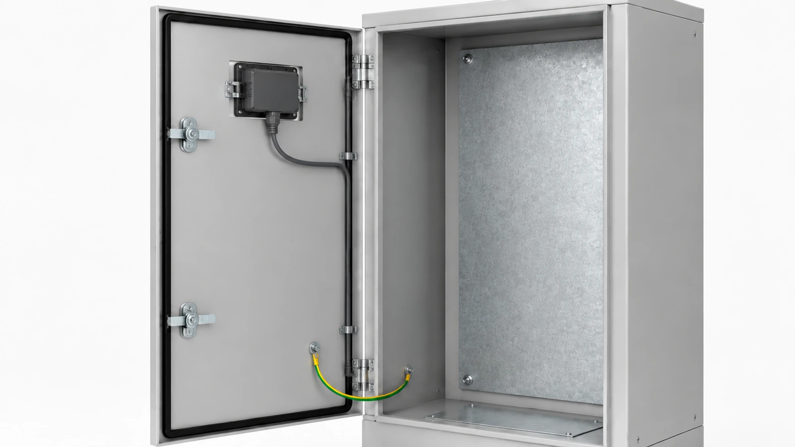
Where a flexible bond is specified, review its route throughout the door’s intended travel. Check for tension, pinching, rubbing against edges and interference with the latch or gasket. Show where it disconnects if the door is removable.
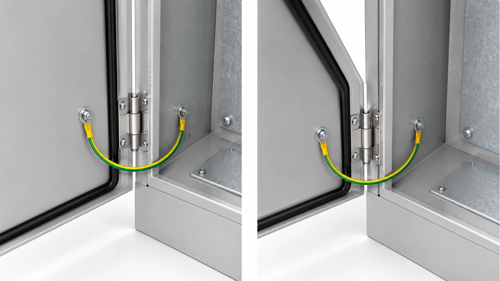
Door-mounted electrical equipment needs its own review. Schneider’s ULP guidance, for example, calls for checking continuity between the door and the protective conductor and specifies a door-to-frame connection for the arrangement it describes. That is system-specific guidance, not a universal wiring detail for every cabinet.
Mounting plate: verify the fixing system’s electrical role
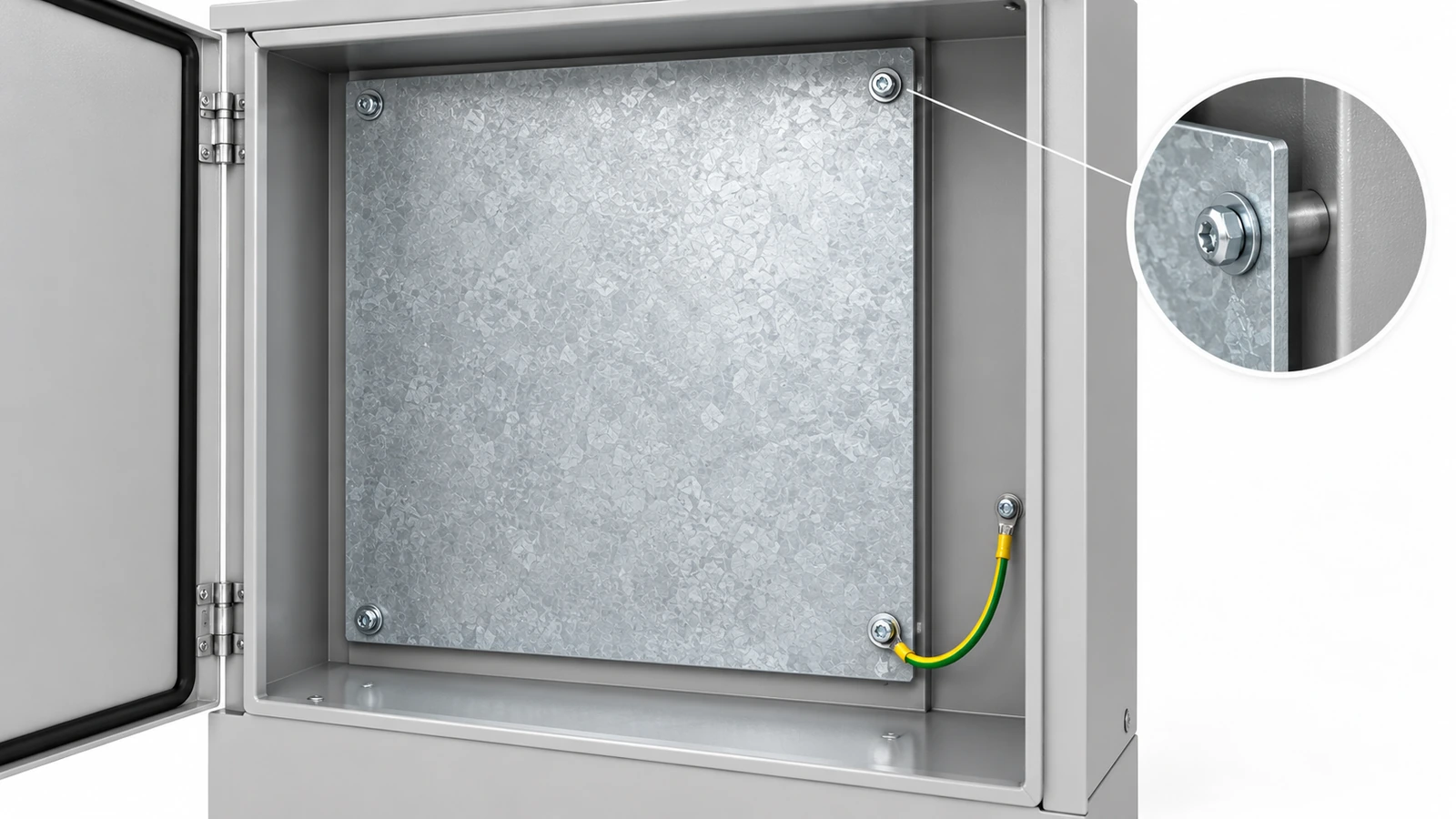
Do not infer the plate’s bonding performance from the number of mounting bolts. Rittal documents automatic contacting for mounting plates and gland plates in its AX/KX enclosure series, but leaves the designer to determine whether that contacting is sufficient for the earthing system.
For the selected construction, identify whether the fixing hardware provides the accepted connection or whether a separate bond is required. Record the hardware and finish together. Refer changes to spacers, washers or plate coating back to the electrical designer instead of treating them as cosmetic substitutions.
Removable panels and gland plates: plan the reassembly
Mark every removable part included in the protective circuit. Ask the designer to confirm whether removing one part affects the required connection to any part left in place. Where a bonding lead must be disconnected, include a visible reconnection point and a reassembly check in the maintenance instructions.
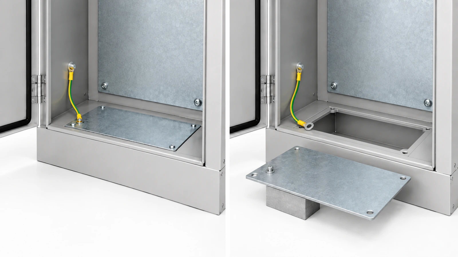
Cable-entry hardware also needs review. UL distinguishes the bonding investigations for metallic outlet boxes from those for cabinets, junction boxes and pull boxes. Do not transfer an assumption about knockout bonding from one product category to another.
Specify how the connection works through the coating
Powder coating can electrically insulate a mating surface. Protocase identifies masking as a way to keep selected areas free of coating for electrical conductivity. Its guidance also notes the corrosion risk of leaving cold-rolled steel unprotected.
Ask the electrical designer and enclosure supplier to agree on the contact method for each interface. The drawing should identify the intended contact area, finish condition and hardware stack. Depending on the approved construction, the solution may use a masked area, specified surface preparation or purpose-designed contact hardware. Rittal’s documented automatic-contact arrangements illustrate why the complete construction matters.
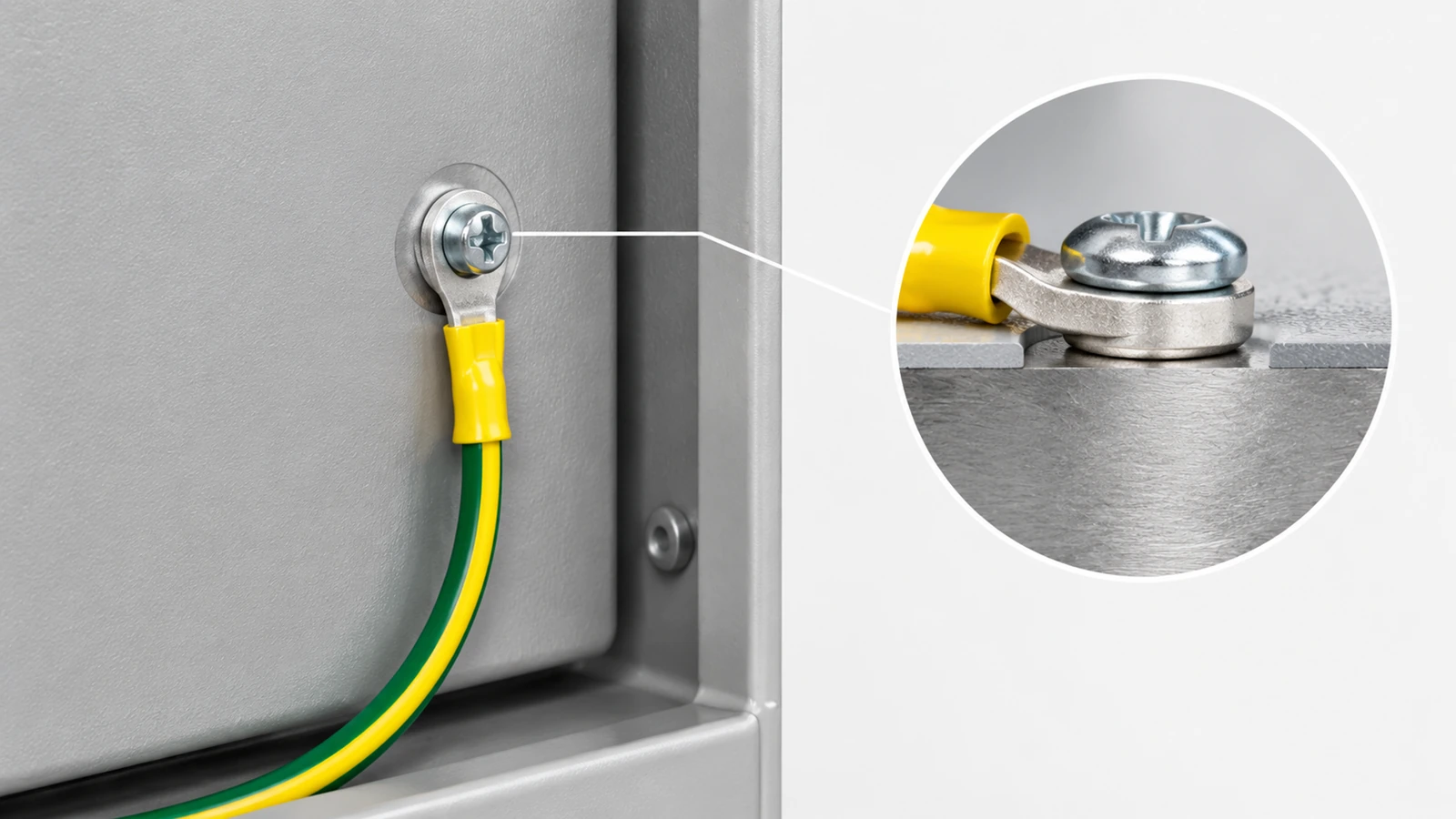
Avoid a general instruction to “remove paint wherever needed.” It leaves the contact geometry and treatment of exposed metal undefined. Equally, do not substitute an ordinary serrated washer for a specified bonding component without approval.
Keep the coating callout limited to what the electrical interface needs. The broader choice of pretreatment, coating system and environmental protection belongs in the powder-coating specification and corrosion review.
Put the supply boundary on the drawing and RFQ
For a custom electrical enclosure, request a bonding-interface schedule with the quotation. A useful schedule includes:
- The two parts connected at each interface, with drawing references.
- The designer-approved connection detail and component references.
- Contact-surface and finish requirements.
- Any movement, removal or access requirements.
- What arrives fitted, what arrives loose and what the panel builder must supply.
- Inspection requirements for the enclosure as delivered.
- Verification required after electrical assembly or site installation.
Separate the supply status of each interface into four possible scopes:
| Supply status | What the quotation should make explicit |
|---|---|
| Provision only | The supplier makes the specified mounting or contact feature; other bonding components are excluded |
| Loose components | The specified hardware is included, with assembly assigned to another party |
| Factory-assembled connection | The supplier installs the defined connection and performs the agreed enclosure-level checks |
| Final electrical connection | The named electrical assembly or installation party connects the enclosure to the project protective circuit and verifies that scope |
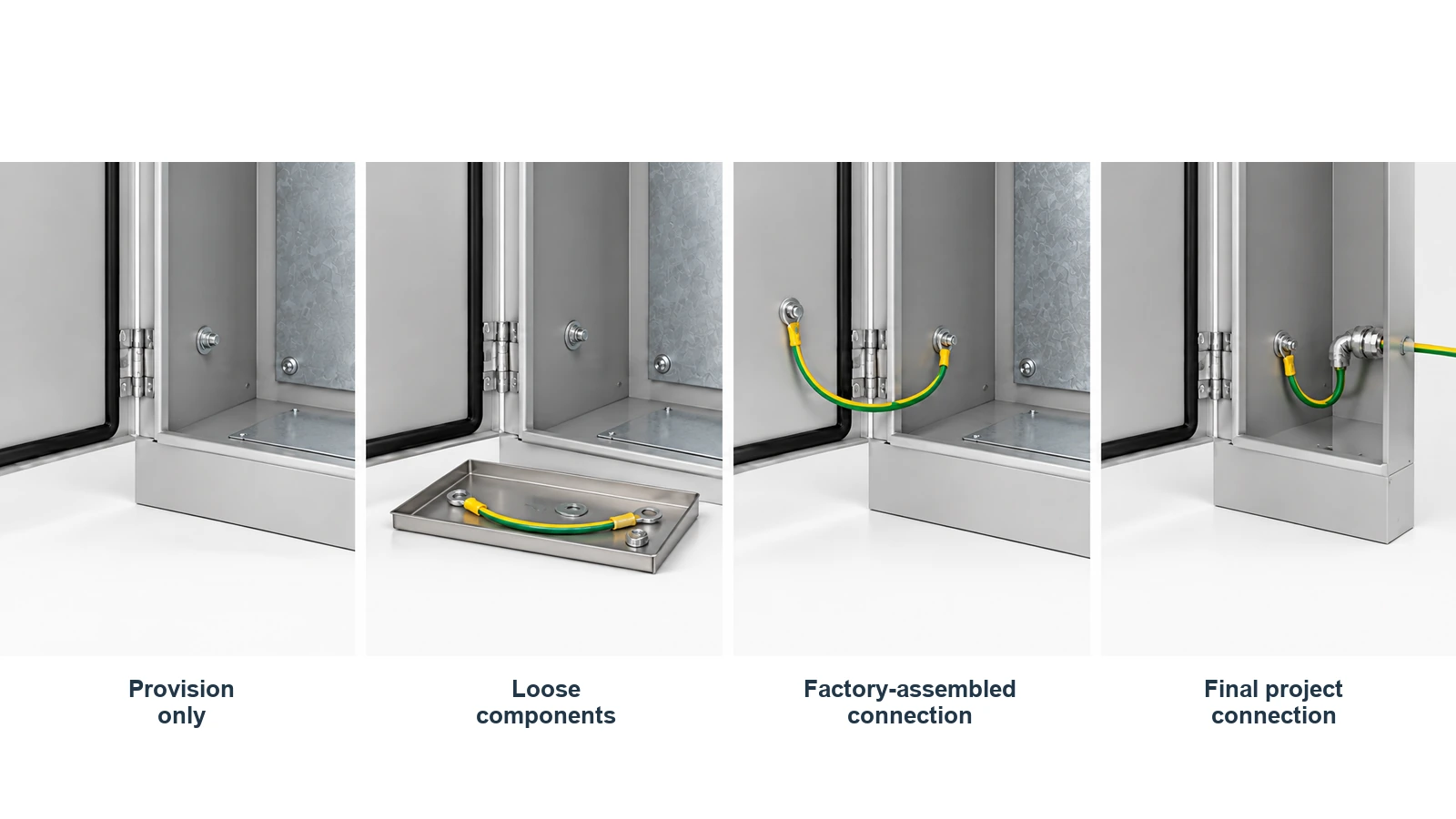
This distinction matters when a BOM uses a vague description such as “grounding kit.” nVent’s accessories sheet includes grounding kits whose cables are excluded, alongside other grounding products. Check the contents of the exact kit being quoted.
Assign responsibility before approving production
The following is a suggested division to confirm in the purchase documents. The actual contract and applicable requirements govern.
| Party | Responsibility to confirm |
|---|---|
| Project electrical designer | Applicable requirements; parts requiring bonding; accepted connection design; conductor and connection ratings; verification criteria |
| Enclosure fabricator | Agreed mechanical provisions, contact-surface preparation, supplied hardware and inspection of its delivered scope |
| Panel builder or electrical assembler | Installation of the protective circuit and bonding components within its scope; checks after equipment assembly |
| Site installer | Connections and checks affected by installation or site modification |
| Buyer or quality team | Drawing revision control, required records, scope acceptance and closure of deviations |
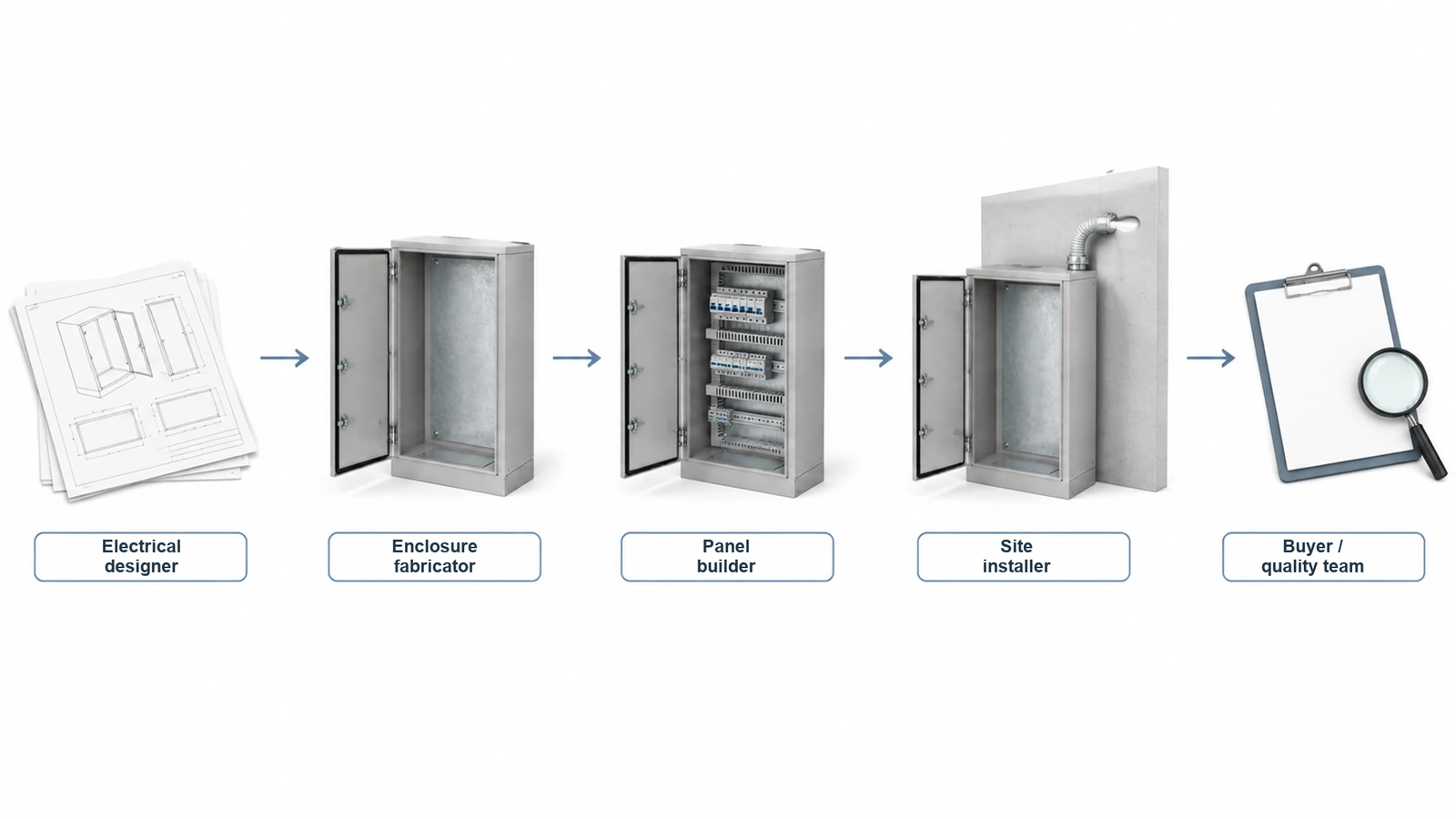
If the fabricator is supplying an empty cabinet, say so. Do not leave the buyer to infer whether “grounded enclosure” means prepared connection points, fitted bonding components or a verified finished electrical assembly.
Agree on acceptance evidence before production
Create separate acceptance requirements for the empty enclosure and for the completed electrical assembly. Ask the supplier to state exactly what it will inspect or test, in which configuration, and what record it will provide.
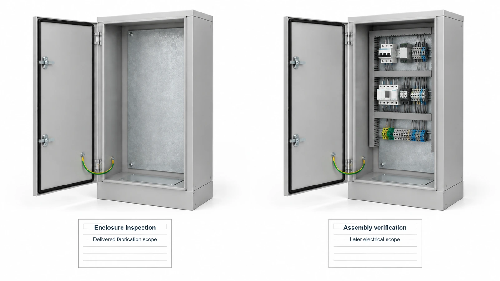
For the enclosure as delivered, the inspection plan can cover:
- Presence and location of the specified bonding provisions.
- Correct components, contact surfaces and assembly details.
- Identification of fitted and loose parts.
- Door movement and access to the connections.
- Any specified continuity checks between identified endpoints.
- Photographs or records tied to the cabinet and drawing revision.
Have the electrical design authority define the test method, endpoints, acceptance limits and required equipment. A result should identify the configuration tested, including whether the mounting plate and removable parts were installed.
Continuity evidence has a limited scope. Rittal’s technical documentation addresses both connection resistance and short-circuit testing. A continuity reading by itself does not demonstrate every aspect of protective-circuit performance or approval of the completed assembly.

Before handover, assign any checks required after transport, electrical assembly, panel removal or field modification. Record who closes those items before energization. An enclosure inspection record should not be presented as verification of work completed later by another party.
FAQ
Does an empty enclosure include the bonding cables?
Check the exact supply scope. Some grounding kits include cables and hardware; others exclude cables. Ask the quotation to identify what is fitted, supplied loose or excluded for the body, door and mounting plate.
Can the same connection provide protective bonding and EMC grounding?
It may serve both purposes if it is designed and verified for both. The purposes remain different, so an EMC connection should not be accepted as protective bonding solely because it is conductive.
What grounding conductor size or tightening torque should the drawing specify?
Ask the responsible electrical designer to specify the conductor and connection requirements, and reference the exact hardware manufacturer’s installation instructions. Put the approved values on the controlled drawing or assembly instruction. Keep unresolved values off the production release.
Send the enclosure drawing with the bonding scope
For an FN Enclosure quotation, send the cabinet drawing, material and finish specification, door-mounted equipment layout, removable-part details and the electrical designer’s bonding-interface requirements. Mark any unresolved items for review before production.
Ask the quotation to distinguish mechanical provisions, included hardware, factory assembly and final electrical verification. Send your drawings and enclosure requirements so those responsibilities can be discussed alongside the fabrication scope.