

Start VFD selection with motor current and the machine’s load profile. Horsepower narrows the search; supply, overload duty, control, communications and cooling decide which drive fits. We would choose the lowest-cost configuration that meets those requirements and supports the maintenance team’s recovery plan.
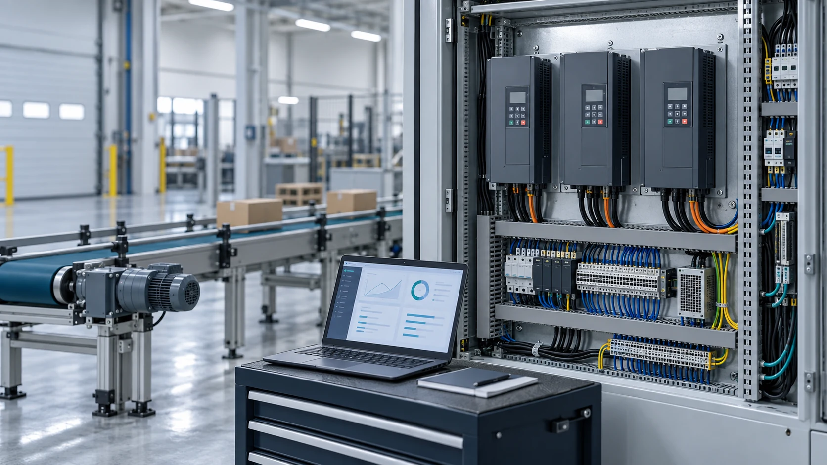
Danfoss’s sizing guidance goes beyond horsepower to the electrical and operating details. Work through these six checks before ordering.
| Check | What to verify | Question before ordering |
|---|---|---|
| Supply + motor | Voltage, phase and motor type; nameplate current and speed | Does the drive match the motor and supply? |
| Load + duty | Starting torque, speed range, acceleration and overload | Does the drive cover the current profile? |
| Control | Speed, torque or process; feedback and stopping | Does the control mode fit the machine? |
| Interfaces | PLC, protocol and I/O; exact options and device files | Can the system exchange the required signals? |
| Installation | Dimensions, losses and clearances; environment and cooling | Can it operate safely in the cabinet? |
| Maintenance | Fault diagnosis, spares, backup, access and restart plan | Can the team diagnose, restore and restart it? |
Start with the machine’s worst operating point
We start with the motor nameplate and the hardest part of the cycle. Record whether the conveyor starts loaded, crawls with material on the belt or needs to stop quickly. Use those load and acceleration requirements to define the current and overload reserve.

Keep the incoming supply and motor data separate. Record the supply voltage and phase, then the motor voltage, phase, rated current, frequency and speed. If the site has only single-phase input, specify a drive approved for that input and motor. A standard VFD is not automatically suitable for every single-phase motor. KEB’s single-phase VFD guidance explains why the input arrangement needs a separate check.
An existing motor needs a separate check. Verify inverter-duty suitability, insulation, bearings and the intended speed range. The same power rating does not tell us whether the motor can handle the insulation, bearing and thermal stresses of inverter operation.
Then define what the drive has to control. Steady speed, low-speed torque, fast response and precise positioning point to different control methods. V/Hz, sensorless vector and feedback-based control solve different jobs. Check which motor types the selected control mode supports.
Conveyor example: comparing Siemens V20, G200 and G120C
For this conveyor, the drive must communicate with the PLC, carry the load, fit the cabinet, support fault recovery and justify its cost. V20, G200 and G120C reach that result in different ways.
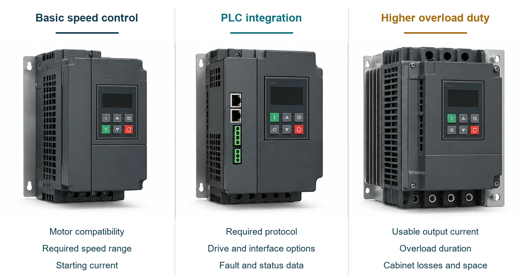
Take a standard conveyor with an S7-200 SMART PLC, a required PROFINET network and motors in the 2–3 kW range. V20 looks attractive on price. G120C offers broader capability. G200 sits between those choices, with PROFINET and wider motor/control options in a smaller general-purpose drive. We compare all three against the same conveyor requirements.
A lower purchase price can disappear once protocol work, extra wiring or manual troubleshooting are added. A higher-rated drive can also be wasted if the machine never uses its added functions. Compare the installed configuration. Treat safety functions such as STO as a separate requirement; a simple conveyor does not make them unnecessary.
1. Start with the conveyor’s actual requirements
“Two or three kilowatts” is only the first filter. For each motor, record voltage, rated current, frequency, speed and motor type. Then describe the difficult moments: loaded or empty start, low-speed crawling, material buildup, acceleration and stopping time. Those details tell us more than the word “conveyor.”
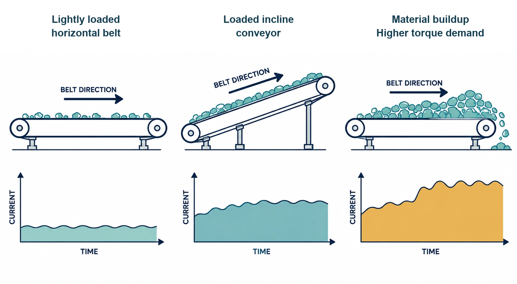
A lightly loaded horizontal belt and a loaded incline conveyor have different starting demands. A mixer can become harder to turn as its material thickens. A crusher can move from normal running to a sudden resistance event. Choose overload duty from the motor-current-versus-time profile.
The control side needs the exact PLC CPU, firmware, engineering software and network design. “S7-200 SMART” identifies a controller family; it does not define a validated drive configuration by itself.
2. Treat PROFINET as a system architecture
A drive can exchange data with a PLC and still miss the project’s PROFINET requirement. Siemens lists USS and Modbus RTU for the V20. Those interfaces can be useful, but serial communication does not replace a native PROFINET device when the project requires one.
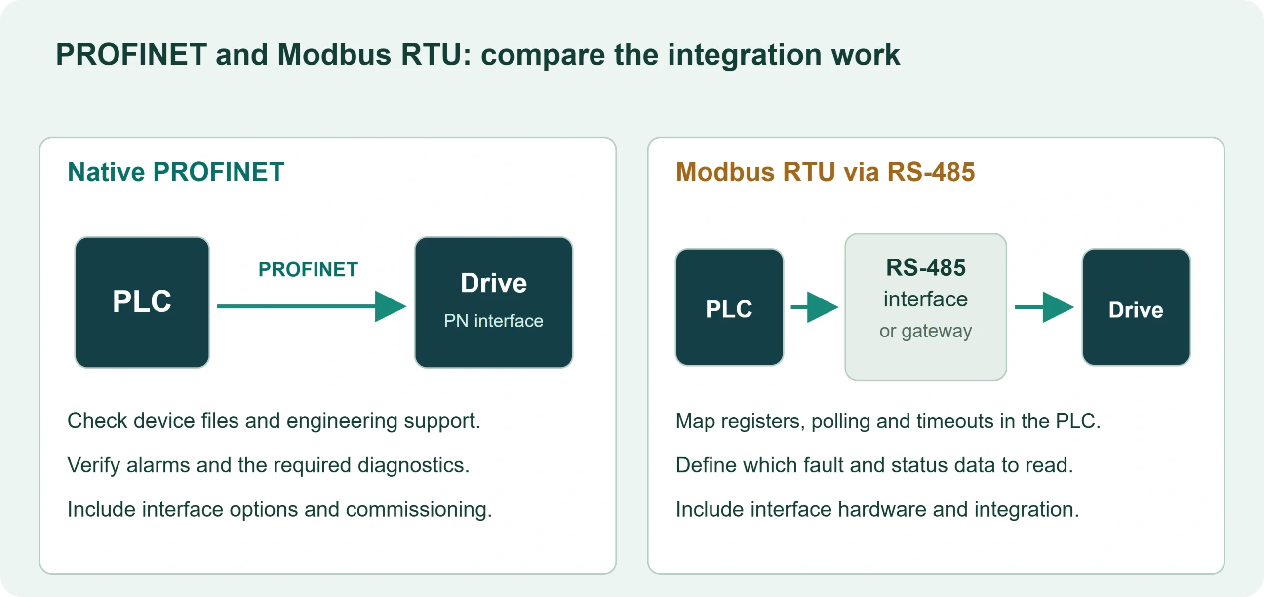
RS-485 may be onboard, a PLC module or a gateway. If Modbus RTU is acceptable, include RS-485 wiring, interface hardware, PLC programming, polling behavior, fault handling, device documentation and the maintenance team’s troubleshooting process in the quote. If PROFINET is fixed, specify the exact drive order number, interface option and engineering workflow that support it.
Compare V20 and G120C as installed packages, not as bare price tags. V20 can fit an independent, simple application that accepts its communication method. The comparison breaks down when the quote hides a protocol conversion and leaves the engineering work outside the price.
3. Check the cabinet fit
A cabinet drawing turns product differences into real costs. The 5.5 kW comparison records a G200 sample at 73 mm wide, roughly one-third narrower than the compared units. Use that as a layout clue, not as a universal G200 dimension. Before fabrication, confirm the exact order number, filter version, mounting pattern, depth, terminal position, cable bend space and clearance.
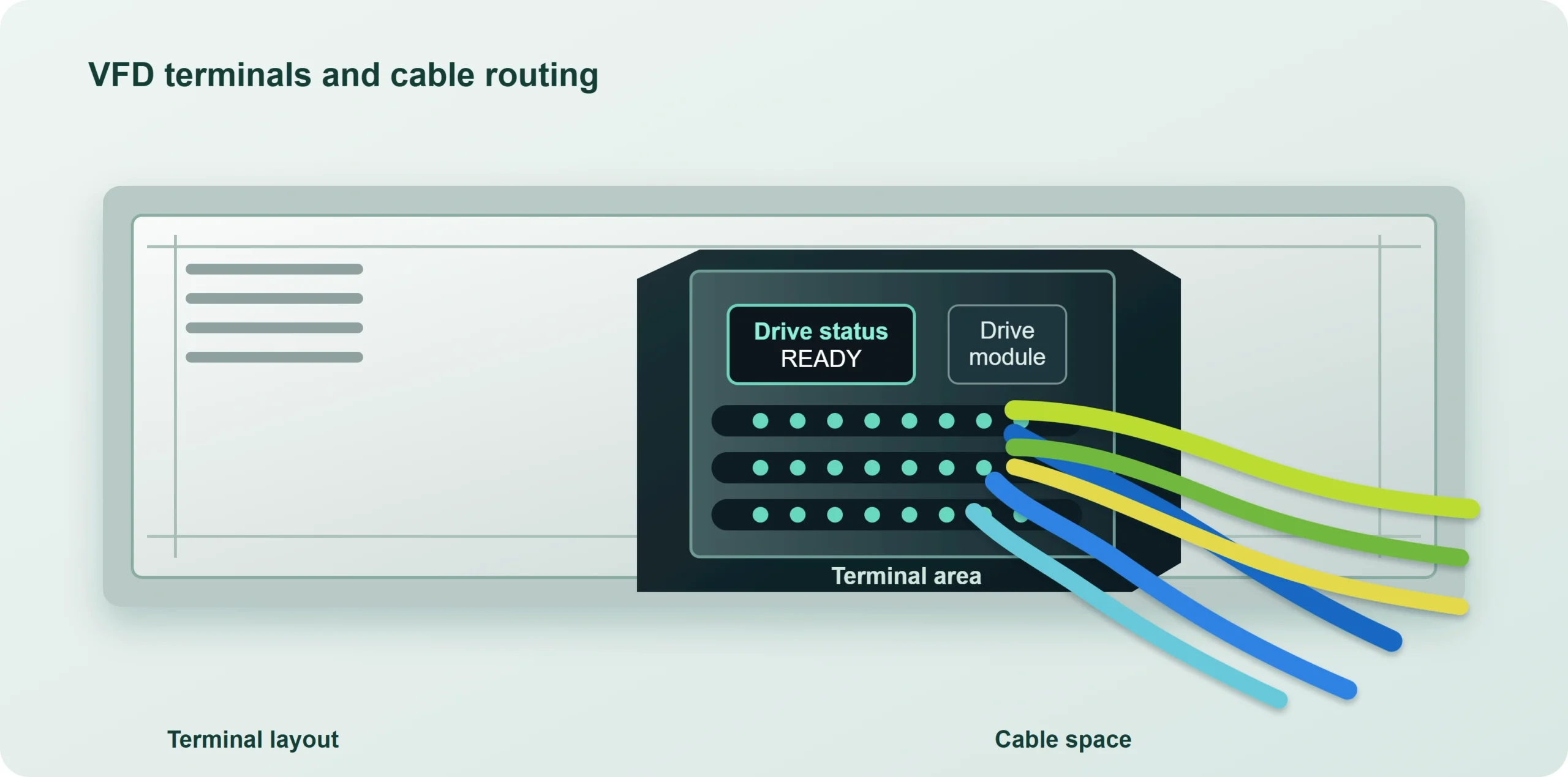
A common late change looks like this: the cabinet is assembled, then someone asks for one more drive. A narrow unit may fit beside the existing hardware. A wider one may force a new backplate, a different cable route or more cooling space. The US G200 product information used here specifies 3 mm side-by-side spacing. Put the manual’s clearance on the drawing; do not write “zero gap.” If the machine is expected to need additional cabinet bays, compare modular electrical enclosures before fixing the layout.
Running several drives on one bus raises a power-quality question. The comparison observes the supply-current waveform with an oscilloscope while several G200 units run at full power. The schematic below shows that review setup. A filter and PWM review does not replace a site-wide harmonic study.
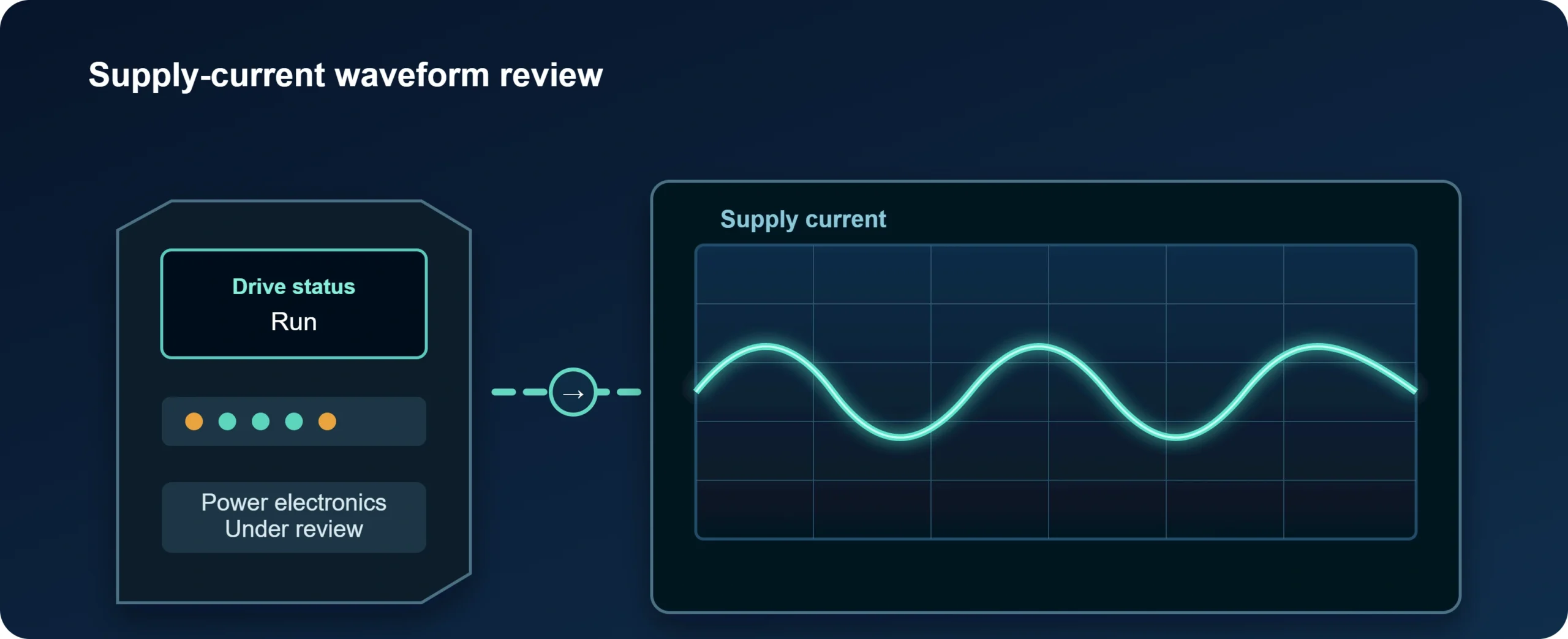
Treat these as separate checks. High-frequency EMC/RFI filtering does not answer questions about low-frequency line harmonics, transformer loading or allowable site distortion. Danfoss treats these as separate design checks. Before removing external equipment, obtain the exact filter configuration, test conditions and site requirements.
4. Read current and overload as one package
Start with an orderable configuration for the required voltage, phase and power. Then check usable output current under the intended installation conditions. The family’s headline kW range is useful for screening, but the current rating decides whether the configuration can do the work.
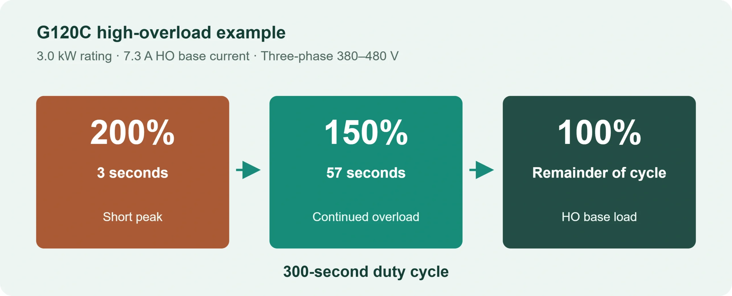
Overload ratings describe different duty points. The comparison describes V20 and G200 with 150% overload for 60 seconds in a five-minute cycle. The documented G120C HO sequence is 200% for 3 seconds, then 150% for 57 seconds, with the remainder at base load. Compare the full current-versus-time curves with the machine’s load profile. A larger percentage does not automatically mean a better rating.
A conveyor with a steady current profile may need less short-duration peak capacity than a spindle starting under a sharp demand. The mixer and crusher examples add another check: how long the higher load lasts.
The G120C manual shows why the percentage cannot stand alone. For one frame-size-A, three-phase 380–480 V entry, the 4.0 kW LO rating has an 8.8 A base-load output current. The 3.0 kW HO rating has a 7.3 A base-load output current. Both sequences sit inside a 300-second cycle. Do not combine the LO current with the HO percentage.
Choose by usable current and actual duty. Move up only when a requirement remains unmet. Upsizing can solve a current or overload gap. Compare the larger unit’s price, dimensions, losses and functions before accepting the change.
Price the complete configuration. For the 0.75 kW G200 versus G120C comparison, request matching order numbers, market, currency, taxes, options and quotation dates. A lower bare-drive price does not establish a lower installed cost. Include communication hardware, engineering and cabinet changes.
5. Plan for control power and fault recovery
Ask what remains powered when the main 380 V circuit is switched off. If the control electronics rely only on the main supply, the display and communications may go dark with the drive. The technician then loses live status during the fault.
If the PLC has to read drive faults while the main circuit is off, specify that behavior. For an external 24 V control supply, check the exact terminals, supported functions, current requirement, isolation arrangement and fault visibility in the selected manual. An Ethernet cable alone does not keep the control board powered. Before electrical work, account for every supply and follow the drive’s isolation, discharge and voltage-check procedure.
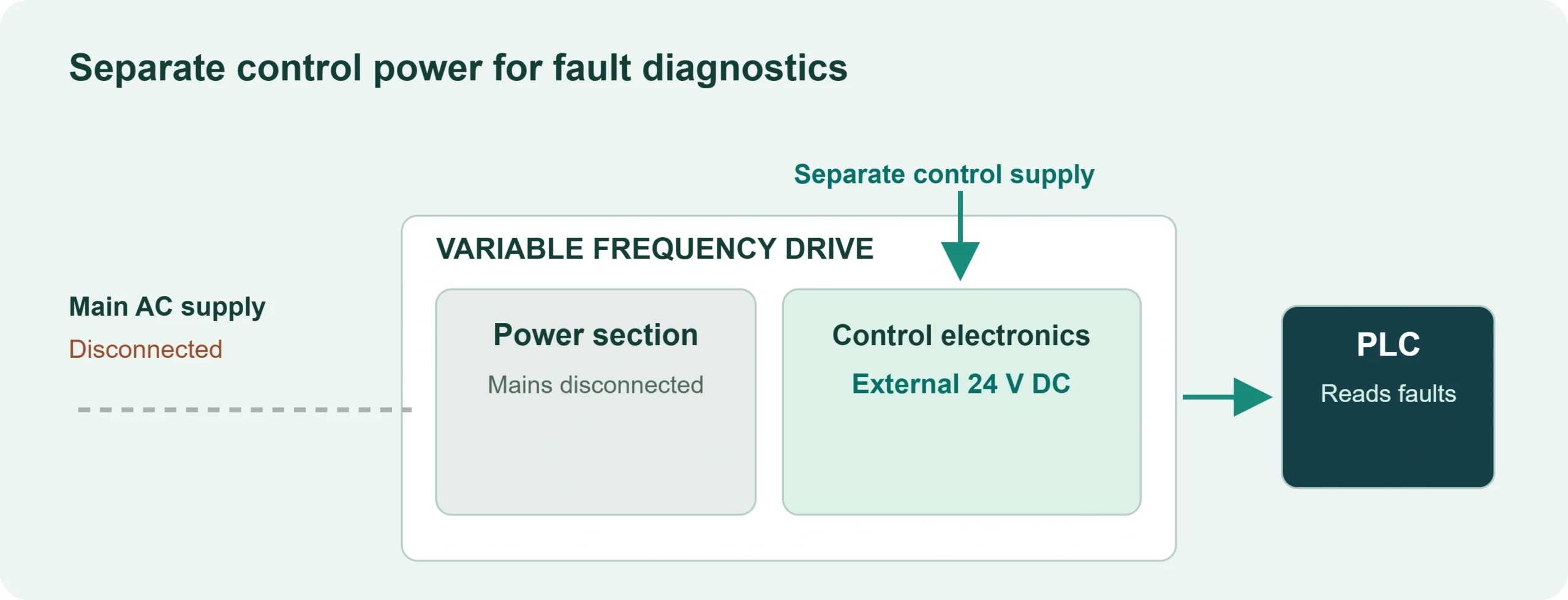
Write the recovery sequence into the quotation and machine records: what the PLC reports after a trip, where the parameter backup is stored, how a replacement drive receives its configuration and which checks are required before restart.
6. Separate motor type from control method
Change the motor from induction to permanent-magnet synchronous and the selection changes with it. The same kW rating does not answer the compatibility question. V/f control can suit a simple induction-motor speed task. A permanent-magnet synchronous motor needs explicit support for its motor type and control algorithm.
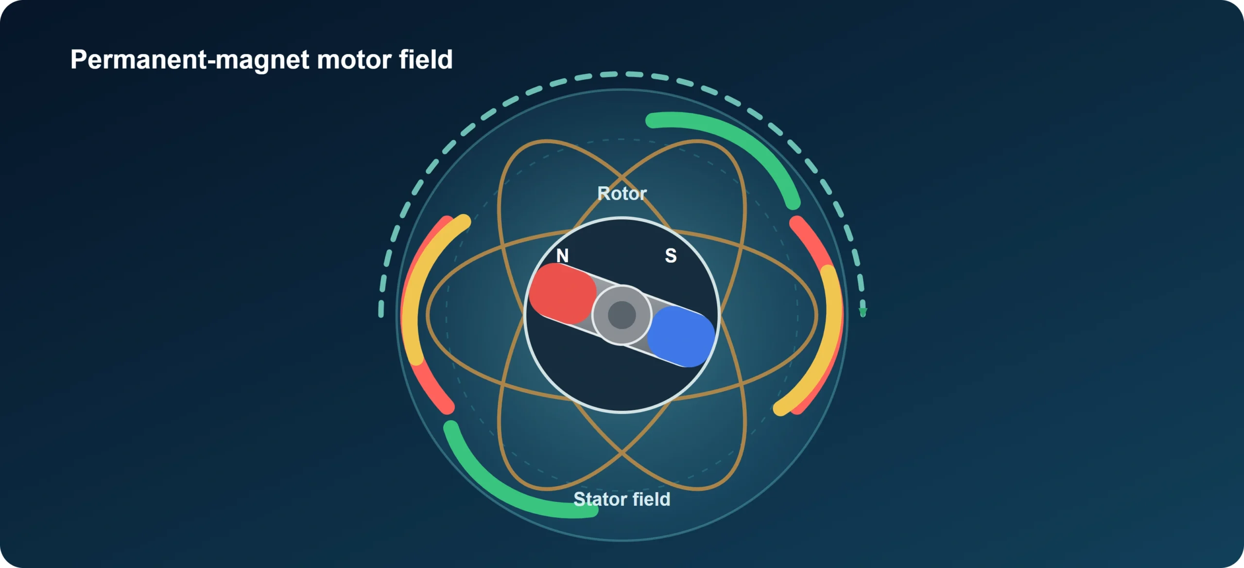
A product page that says “vector control” does not confirm compatibility with every permanent-magnet motor. Check the supported motor table, firmware, parameter procedure, speed range, starting method and any feedback requirement.
The US G200 product information used for this comparison lists sensorless vector speed control and support for asynchronous, permanent-magnet synchronous and synchronous-reluctance motor types. G200 is therefore worth checking when the machine uses a broader motor mix. G120C may be justified by wider power coverage, higher overload duty or required functions. V20 remains reasonable for a simpler approved application using a compatible induction motor and its available communication method.
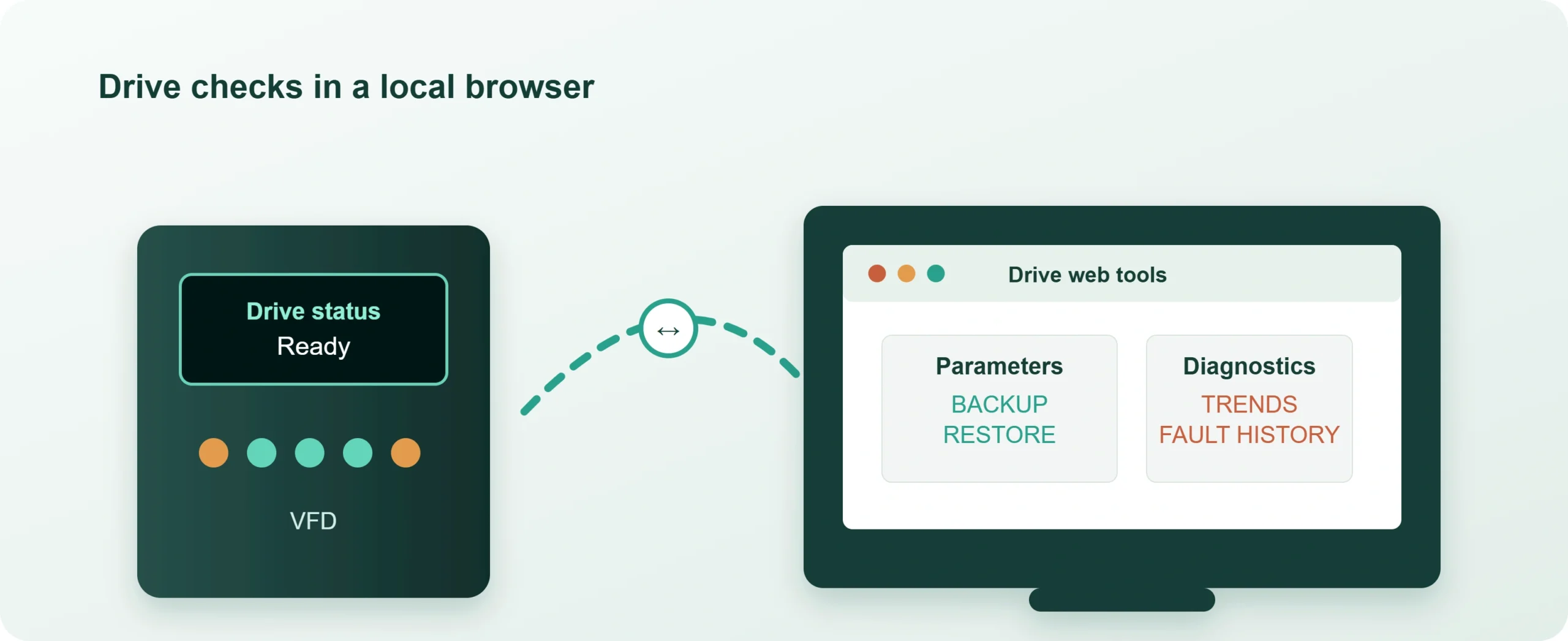
G200’s Web Server can help during setup and fault review. For supported local tasks, a phone or computer can use a browser to change parameters, view trends and check faults without TIA Portal installed. Confirm the network connection and supported functions for the selected version. Keep access control, parameter backups and change records in the commissioning plan.
7. Shortlist the configurations that pass
Use this shortlist only after the current, duty, interface and installation checks pass.
| Situation | Candidate direction | What must still be verified |
|---|---|---|
| Independent, basic application with a compatible induction motor and simple control | V20 may be sufficient | Input supply, motor current, duty, communication method and cooling |
| Small standard application that needs Siemens ecosystem integration, PROFINET and broader motor/control options | G200 is worth evaluating | Regional order number, current, overload, motor table, device files, Web Server and installation data |
| Wider power coverage, higher overload demand or more complex functions | G120C may be justified | Exact HO/LO rating, safety design, communication variant, dimensions and heat loss |
| China-market G200B proposal | Treat as a separate regional product decision | Availability, documentation, firmware and current motor/control features |
Keep a G200B or G200 Basic quotation tied to its regional configuration. Do not treat it as “G200 without vector control.” The UK G200 Basic information used here lists sensorless vector control. For a fan or pump, compare the required control mode, communication, duty and price against the exact regional model and firmware.
Put the full configuration in the RFQ: exact order number, voltage and phase, motor type, rated current, duty class, communication interface, device files, safety requirements, control-power arrangement, dimensions, heat loss, cooling, cable routes and recovery procedure.
The electrical team needs these details to validate the drive. The enclosure supplier needs them to lay out mounting points, openings and cooling space.
Read current and overload ratings together
Use the current available under the intended installation conditions, not the largest number printed in a catalog. Ambient temperature, altitude and operating settings can reduce usable capacity. Apply the selected manufacturer’s derating rules instead of adding a blanket multiplier.
To make the distinction concrete, Siemens’s G120C manual, Table 11-5 gives two duty ratings for one frame-size-A, three-phase 380–480 V entry:
| Rating for the same hardware | Base-load power | Base-load output current | Permitted overload sequence |
|---|---|---|---|
| Low overload (LO) | 4.0 kW | 8.8 A | 150% for 3 seconds, then 110% for 57 seconds |
| High overload (HO) | 3.0 kW | 7.3 A | 200% for 3 seconds, then 150% for 57 seconds |
The manual’s duty-cycle diagram puts each overload sequence inside a 300-second cycle. Each percentage belongs to its own base load.
Do not combine the 8.8 A LO current with the 200% HO overload claim. The HO rating uses a 7.3 A base. Check the applicable installation derating before approving either rating.
Choose the full rating against the required current-versus-time profile. A short peak cannot stand in for a longer loaded acceleration. “Go up one size” is not a substitute for checking the duty.
| Check | What to include | Decision |
|---|---|---|
| Drive-current check | Motor/application current requirement; usable output after derating; overload capability for the actual duty | Does this configuration qualify? |
| Cabinet thermal check | Device loss data; ambient conditions and heat path; clearances and cooling arrangement | Can it operate as installed? |
Approve the drive-current check and the cabinet thermal check separately.
Specify communication and recovery as operating requirements
A protocol name starts the discussion. List the command and status signals, expected behavior after communication loss, fault reset method, device files and parameter-backup procedure. The controls and maintenance teams can then verify what “supports PROFINET” or “supports Modbus” means for the machine.
Cable routing can decide the architecture. On Jafs Machines’ drilling turret, Invertek reports using a PLC and Modbus through slip rings. The rotating assembly made individual drive-control wiring difficult. The physical movement drove the choice of command path.
A replacement needs its own procedure. Rockwell Automation’s beverage-plant report describes replacing PowerFlex 40 drives with PowerFlex 525 drives and using automatic device configuration. Define what loads the settings, what verifies the parameters and what must happen before restart.
Assign the backup owner, approve the spare configuration and list the checks that follow a replacement. If independent control power is required, document how it behaves during mains loss.
Draw cables, airflow and service access
A drive outline on the backplate leaves several dimensions unresolved. Add terminals, cable-entry direction, bend space, mounting holes and the clearance needed to remove the unit. Use FN’s enclosure sizing guide for the mechanical layout review. Define the cable-gland and gland-plate arrangement alongside the cable-entry direction and bend space.
Keep a separate thermal input sheet with drive losses at the selected duty, losses from other devices, ambient conditions and the proposed heat-removal path. Danfoss’s cooling guidance explains why clearances and heat paths matter. If part of the heat is discharged outside the cabinet, show that arrangement instead of assigning every watt to the interior.
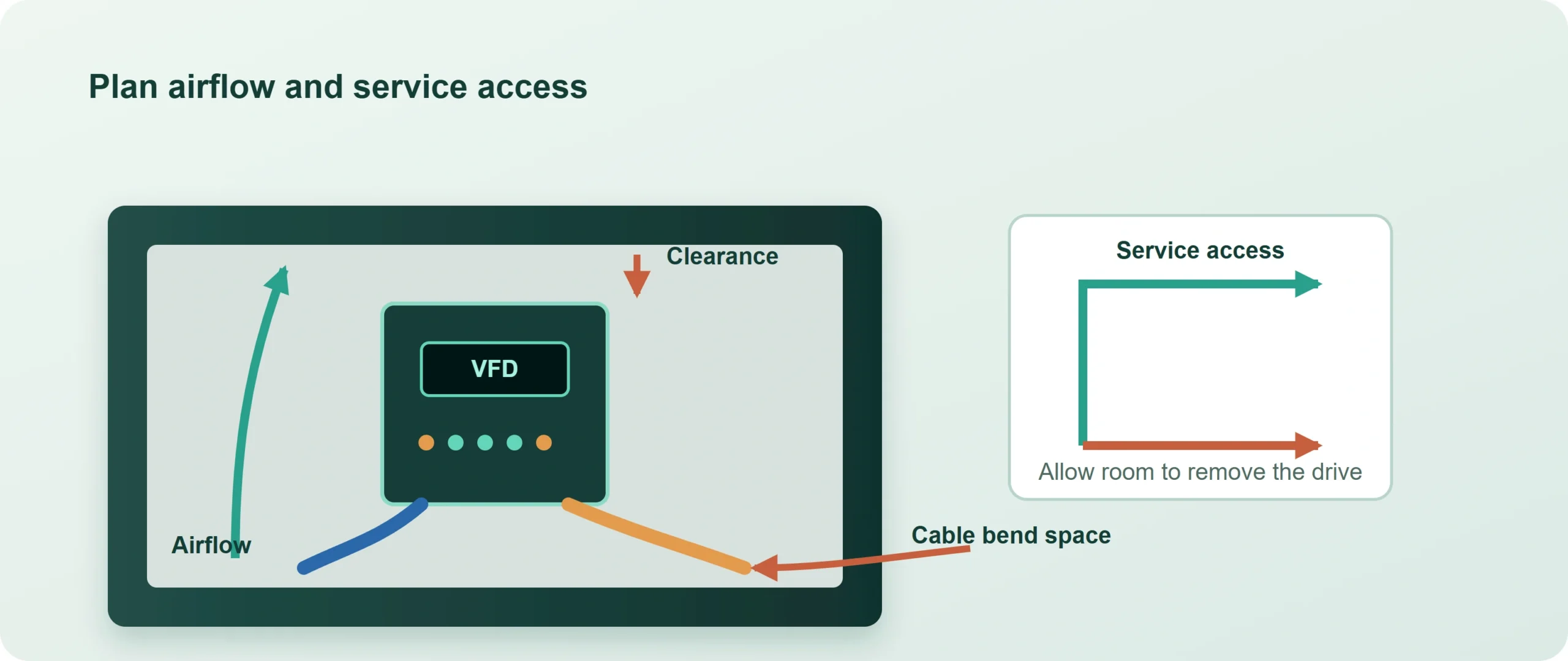
Use the drive’s loss data for the cabinet thermal calculation. Review filtering separately: Danfoss distinguishes high-frequency interference filtering from low-frequency harmonic mitigation. An EMC filter label does not prove that line harmonics have been eliminated. Use the enclosure cooling guide to define the cabinet’s cooling interfaces.
The cleaning environment can change the cabinet decision. Invertek’s Dorner conveyor report describes a selection influenced by connectivity and washdown conditions. Decide early whether the drive belongs near the conveyor in a protected arrangement or inside a suitable cabinet. The choice changes wiring, price and maintenance access. For stainless steel electrical enclosures near washdown areas, specify the material grade, gasket and cable-entry arrangement together.
Compare complete quotes, then release the cabinet RFQ
Put competing quotes on the same scope: drive variant, communication options, braking arrangement, accessories, engineering work and enclosure changes. Include the work and hardware needed to put each drive into service.
For the mechanical quote, send:
| Input | What to include | What it resolves |
|---|---|---|
| Device schedule | Full order numbers, options, quantities and datasheets | Equipment the cabinet must accommodate |
| Backplate layout | Mounting patterns, weights, clearances and service access | Space and support requirements |
| Thermal inputs | Device losses, ambient conditions and cooling arrangement | Heat-management assumptions and openings |
| Door and cable drawings | Device cutout drawings, gland plates and entry directions | Fabrication geometry and cable access |
| Enclosure specification | Material, finish, mounting method, quantity and destination | Comparable manufacturing scope |
| Approved drawing | Revision, critical dimensions and agreed inspection records | What will be built and checked |
An HMI opening needs the device drawing and its position. Specify the enclosure cutout and sealing details before fabrication; “leave room for an HMI” does not define the hole.
Your system team owns drive selection, wiring, protection, safety and commissioning. FN manufactures the body, door, mounting plate, cutouts and agreed hardware from approved drawings. Define that industrial-automation enclosure scope in the RFQ so every supplier quotes the same work.
| System / electrical team | Mechanical handoff | FN enclosure scope |
|---|---|---|
| Drive and option selection Electrical design and wiring Control and safety functions Thermal design responsibility Commissioning and system tests | Exact BOM and datasheets Layout, clearances and losses Cutouts and cable-entry files Material and mounting points Approved drawing revision | Body, door and mounting plate Agreed cutouts and hardware Defined mechanical interface Drawing-based manufacture Agreed inspection records |
The quotation and approved BOM define the actual supply scope.
Send FN your layout and enclosure requirements, selected drive datasheets, losses, clearances, quantity and destination. Mark what is fixed and what is still open. The drawing and quotation review is where openings, mounting features, supply scope and revision are agreed before fabrication.
Frequently asked questions
No. Use horsepower to narrow the search, then check motor current, overload duty, motor compatibility and installation conditions. The G120C table shows why one hardware platform can carry different power and current ratings for different duties.
No. Compare the base current, overload duration and cycle with the machine’s load profile. A higher short peak does not replace a lower overload rating available for longer.
No. Select the interface the machine requires, then verify the exact PLC, drive, options and device files. The conveyor example is about protocol fit, not brand matching.
Only if the selected drive supports it. Check for a separate control supply, the functions that remain powered and whether the PLC can still access fault information under that arrangement.
Yes, for a preliminary quote. Send the available layout and mark missing dimensions, losses and interfaces. Treat those items as quotation assumptions until they are resolved. Production follows the approved drawing and mechanical scope.