

A current transformer cabinet, usually called a CT cabinet, houses the current transformers used in an electrical metering installation. The transformers provide the meter with a signal representing the current in the service conductors, so the meter does not carry the full service current. The revenue meter may be mounted separately. A suitable cabinet — a metal metering enclosure, usually stainless or galvanized steel — must match the metering arrangement and the serving utility’s requirements.

For procurement, the first distinction is scope. An empty enclosure, a cabinet with specified mounting hardware, and an assembled metering unit are different purchases. Their descriptions can look similar even when the CTs, meter socket, test equipment and wiring come from different suppliers. We fabricate the metering body itself, with CT openings, gland-plate provisions and mounting plate cut to your drawing; stainless steel meter boxes are built the same way, without a fixed catalog size.
Where a CT cabinet fits in the electrical service
In a self-contained metering installation, the service current passes through the meter. Transformer-rated metering uses CTs to provide the current inputs instead. The meter combines those inputs with voltage measurements to determine electrical energy use.
The serving utility determines which arrangement is acceptable. Service voltage, phase configuration and capacity can change the answer. For example, Puget Sound Energy’s non-residential service handbook distinguishes self-contained metering, separate CT enclosures and switchboard metering. A single amperage threshold cannot describe all three arrangements or every utility territory.
A separate CT enclosure gives the metering transformers their own compartment, with metering circuits routed to the meter socket. In switchboard metering, the CT compartment is part of the switchboard and its construction must be coordinated with that assembly. The utility’s permitted arrangement determines whether a separate cabinet is appropriate.
The terms CT cabinet, meter enclosure and service disconnect describe different functions. A separate CT cabinet does not automatically include the revenue meter or a disconnecting device.

A Milton, Wisconsin, Well No. 5 construction RFI reported that equipment shown as an exterior service disconnect was actually only a CT cabinet. The proposed correction added a fused disconnect and changed the equipment layout. The record documents a requested change rather than a completed repair, and shows why the service drawing must identify CT metering and disconnecting equipment separately.
What should come with the cabinet?
A CT cabinet quotation needs a defined physical scope. Useful distinctions include:
| Quoted scope | What it covers | What remains to be assigned |
|---|---|---|
| Fabricated enclosure | The specified cabinet body, door, access panels and openings | CT supports, transformers, terminations, meter equipment and electrical assembly |
| Enclosure with mounting provisions | The enclosure plus the backplate, brackets or CT mounting system identified on the drawing | Which CTs fit the supports, who supplies them, and who completes the electrical connections |
| Assembled CT metering unit | The components expressly listed in its bill of materials | Field connections, any separate meter equipment, utility responsibilities and final approval |
These are ways to describe a purchase, not universal product categories. The bill of materials decides what is included.

An owner may also buy equipment that another contractor installs. In the Hillside Electrical Switchgear Upgrade tender, the Town of Needham specified an owner-furnished CT cabinet installed by the contractor. The same addendum separated responsibility for the utility transformer, medium-voltage cables and primary conduits.
For the enclosure buyer, the useful question is where the cabinet supplier’s work ends. A wall mounting hole, an internal CT bracket and an electrical termination are three different interfaces. Including one does not establish who supplies or installs the others.
How the CT and conductor layout determine cabinet size
The CT opening and the cabinet interior solve different fit problems
For a window-type CT, the conductors must fit through the transformer opening. Conductor insulation matters: the nominal wire size describes conductor area, not the complete insulated diameter. Multiple conductors also need room in their intended arrangement.

Continental Control Systems’ CT opening guide addresses this directly and recommends using actual conductor dimensions when fit is close. Its table gives guidance for standard round conductors and notes that insulation thickness varies. A cabinet can have ample empty space while the selected CT window is too small for the conductors.
The enclosure then has to accommodate the CT body, its support and the conductors approaching and leaving it. With a bar-type CT mounting arrangement, the termination locations and mounting geometry matter as well. A larger outer box does not correct a mismatched mounting base.

This is why “an 800 A CT cabinet” is an incomplete fabrication description. The CT model, mounting arrangement and cable schedule explain what must fit inside. The current rating alone cannot locate the mounting holes or cable entries.
Cable entries need space all the way to the terminals
A conduit opening can fit on a cabinet wall yet leave an awkward route to the connection point. The relevant space includes the conductor approach, the bend into the termination and access for making that connection.
Utilities may reserve particular areas for incoming and outgoing conductors. NorthWestern Energy’s Montana service requirements, for example, specify entry arrangements and separate compartments for certain CT-metered services. Those layouts are tied to that utility’s service configurations.
Moving an opening to another side can change the conductor route through the CT area or the space available for the mounting system. The useful design sequence is to position the CTs and terminations, establish the cable routes, and then finalize the enclosure openings.
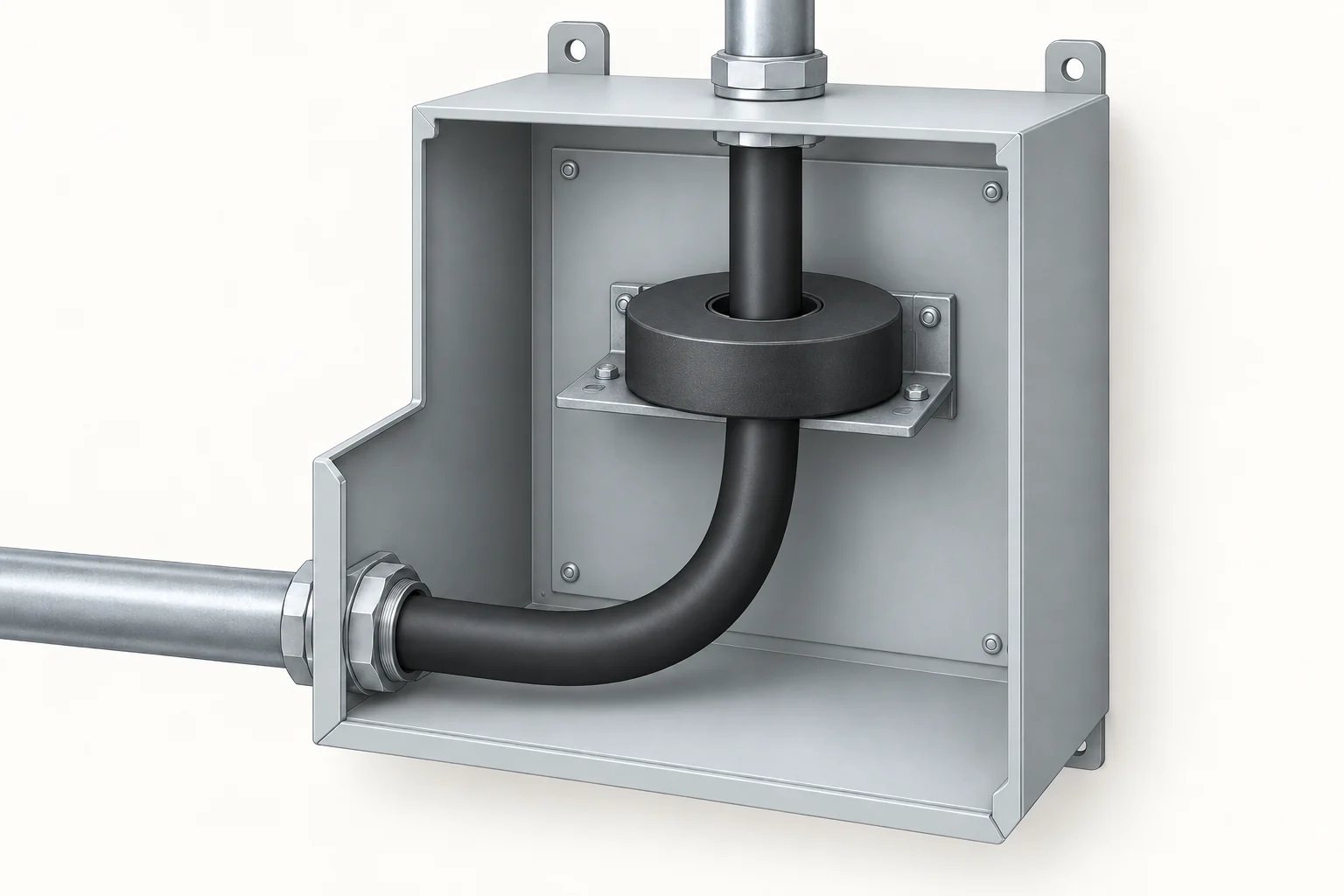
Where the approved design uses a mounting plate, its offset from the rear wall also affects usable depth. Mounting-plate fixing and removal details help resolve that interface. A removable plate should only be used where the metering design permits it; removability is not a substitute for the utility’s required CT support.
A separate meter changes the secondary wiring route
A CT cabinet can be in one location while the meter and test equipment sit in another. That separates the primary conductor space from the route used by the metering circuits.
The distance between the enclosures then becomes part of the electrical design. In conventional current-output CT circuits, secondary lead resistance contributes to the connected burden, which can affect measurement accuracy. Accuenergy’s CT burden explanation describes that relationship. A remote meter position therefore cannot be assessed only by whether a conduit will physically reach it.

The CT output and meter input must also match. Continental Control Systems, for example, describes sensors with internal burden resistors and a 0.333 V AC output in its current transformer FAQ. Those product-specific instructions do not define the requirements for conventional current-output CT circuits.
Conventional current-output CT secondaries must not be left open while primary current is flowing. Janitza’s CT operating guidance explains the hazard and the role of short-circuiting provisions. The enclosure layout therefore needs to show where the specified test or shorting equipment sits and how a technician can reach it. The cabinet fabricator should follow that electrical design rather than choose the secondary-circuit arrangement.

Access and water exposure are part of the layout
A closed cabinet may fit a wall space while its open door obstructs the working area or an exit. CT installation, terminal access and later meter work require usable space in front of the equipment, as well as room inside it.
PSE’s handbook illustrates how specific those conditions can be: its CT enclosure provisions address door opening direction, working clearance, access and utility locking or sealing. These are requirements for PSE installations, not dimensions to copy into every project. The equipment-room drawing needs to show the door in its open position and the surrounding equipment, not just the cabinet outline.

Water can also reach a cabinet from an adjacent service. The Ellsworth Public Library building assessment recorded leakage from a telephone conduit running above a basement CT cabinet, with significant corrosion on the cabinet. The report recommended addressing the leak and repairing the affected surfaces; it did not establish that the enclosure’s original rating caused the damage.
For a replacement cabinet, that evidence changes the scope of the work. Replacing the metalwork leaves the identified water source in place unless the conduit leakage is addressed too. Site photographs and the route of nearby services can be as relevant to the enclosure specification as the nominal indoor or outdoor location.

What utility approval means for ordering
Utility acceptance applies to a particular metering arrangement and the equipment used in it. An enclosure’s material or environmental rating does not, on its own, establish that the utility will accept its CT supports, cable entries, meter interface or sealing provisions.
The distinction is explicit in We Energies’ meter mounting device requirements. Its listed equipment is acceptable for specified metering and service-termination purposes, while the customer or contractor remains responsible for its suitability for the installation. The document also explains why a complete catalog number matters: a suffix can distinguish opening locations or other variations.
A custom enclosure needs the same clarity about the applicable acceptance route. PSE, for example, requires manufacturer drawings for CT enclosures to be submitted for approval before shipment.

The approval route should be resolved before committing to a cabinet design. If the utility requires a listed model or a particular mounting arrangement, those conditions constrain the purchase. If a custom design can be submitted, the submission must show the actual interfaces rather than rely on a statement that the cabinet is “built to utility requirements.”
Turning the metering design into an enclosure order
The single-line drawing establishes the electrical relationship between the CTs, meter and disconnecting equipment. The site layout locates that equipment. The CT and termination drawings, together with the cable schedule, establish what occupies the enclosure. The cabinet general arrangement locates the mounting points and openings and specifies the internal depth, door swing and installation dimensions.
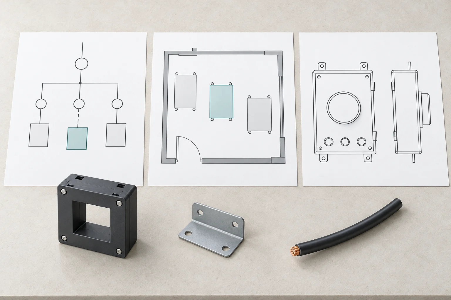
The supply schedule then assigns the parts shown on those drawings. It should distinguish enclosure fabrication from CT installation, electrical connections and metering equipment. Otherwise, a complete-looking layout can still leave an unassigned mounting base or a meter connection that neither supplier included.
If the utility arrangement is still unresolved, the next useful step is a metering-design decision with the responsible designer and utility. Once that arrangement is established, the enclosure drawing and component information can support a cabinet-body quotation.
For that stage, FN’s custom electrical enclosure fabrication page explains the drawing information used to define cabinet bodies, mounting provisions and openings. The CT metering design and its utility acceptance remain part of the project’s electrical scope.
FAQ
Does a CT cabinet replace the service disconnect?
A separate CT cabinet houses metering transformers; it does not automatically provide a means of disconnecting the service. The single-line drawing must identify the service disconnect separately from CT metering. A cabinet’s size or position beside the meter does not establish its electrical function.
Does a CT cabinet quotation include the transformers and meter?
Only if the quoted bill of materials includes them. A quotation may cover an empty enclosure, mounting provisions or an assembled metering unit. Assign the CTs, supports, terminations, meter equipment and electrical connections individually so that the cabinet supplier’s scope and the installer’s responsibilities are clear.
Can I order a CT cabinet by amperage alone?
No. An amperage description does not define the CT model, conductor dimensions, mounting geometry or entry locations. Those details determine whether the conductors fit the CT window and how the equipment occupies the cabinet. Start with the utility-permitted arrangement, CT drawings and cable schedule.
Can the revenue meter be mounted away from the CT cabinet?
Yes, where the utility’s permitted arrangement uses a separate meter enclosure. The connecting route becomes part of the metering design because secondary lead resistance can add burden in conventional current-output CT circuits. The designer must coordinate meter location, wiring and the specified test or shorting equipment.
Does utility acceptance cover a modified catalog cabinet?
Do not assume that it does. Utility acceptance relates to the specified equipment and metering arrangement; catalog suffixes can distinguish different opening locations. If openings or mounting provisions change, establish whether the revised configuration needs a new submission before ordering. An enclosure rating alone does not resolve acceptance.
What drawings support a cabinet-body quotation?
Provide the single-line drawing, site layout, CT and termination drawings, cable schedule and cabinet general arrangement, together with the applicable utility requirements. These establish electrical relationships, equipment positions and physical interfaces. A supply schedule then assigns the components and installation work, allowing the quotation to define exactly where enclosure fabrication ends.