

An EMI shielding enclosure needs a conductive shielding boundary that remains effective across its walls, doors, joints, vents and cable entries. Copper, aluminum, steel and conductive coatings can all have a role. Their performance in an assembled enclosure depends on the interference frequency, the field conditions and how those interfaces are built.[33][34]
Start with a performance requirement tied to a defined configuration. Choose materials against that requirement, review every opening, and ask for test evidence that identifies the actual assembly. A material data sheet alone cannot establish the shielding performance of a finished cabinet.[85]
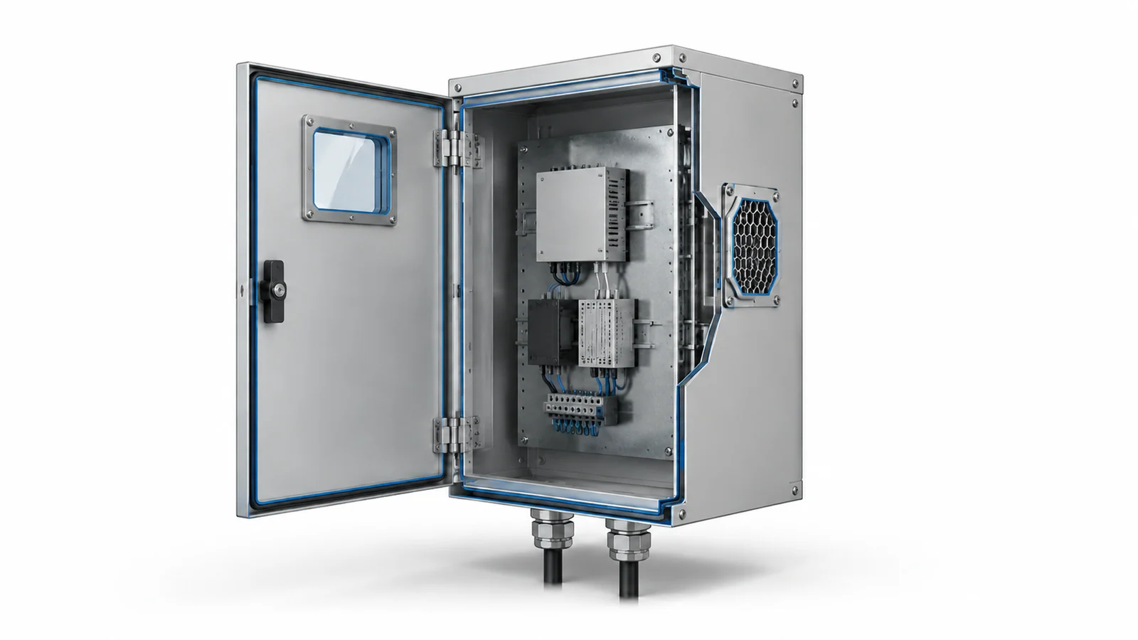
Define the shielding requirement before choosing a material
Start with the interference problem. Is equipment inside the cabinet emitting noise into nearby systems, or does an external source disrupt the equipment inside? Identify the source, the affected equipment and the frequencies of concern. A nearby low-frequency magnetic source requires different shielding considerations from a distant RF source.[33]
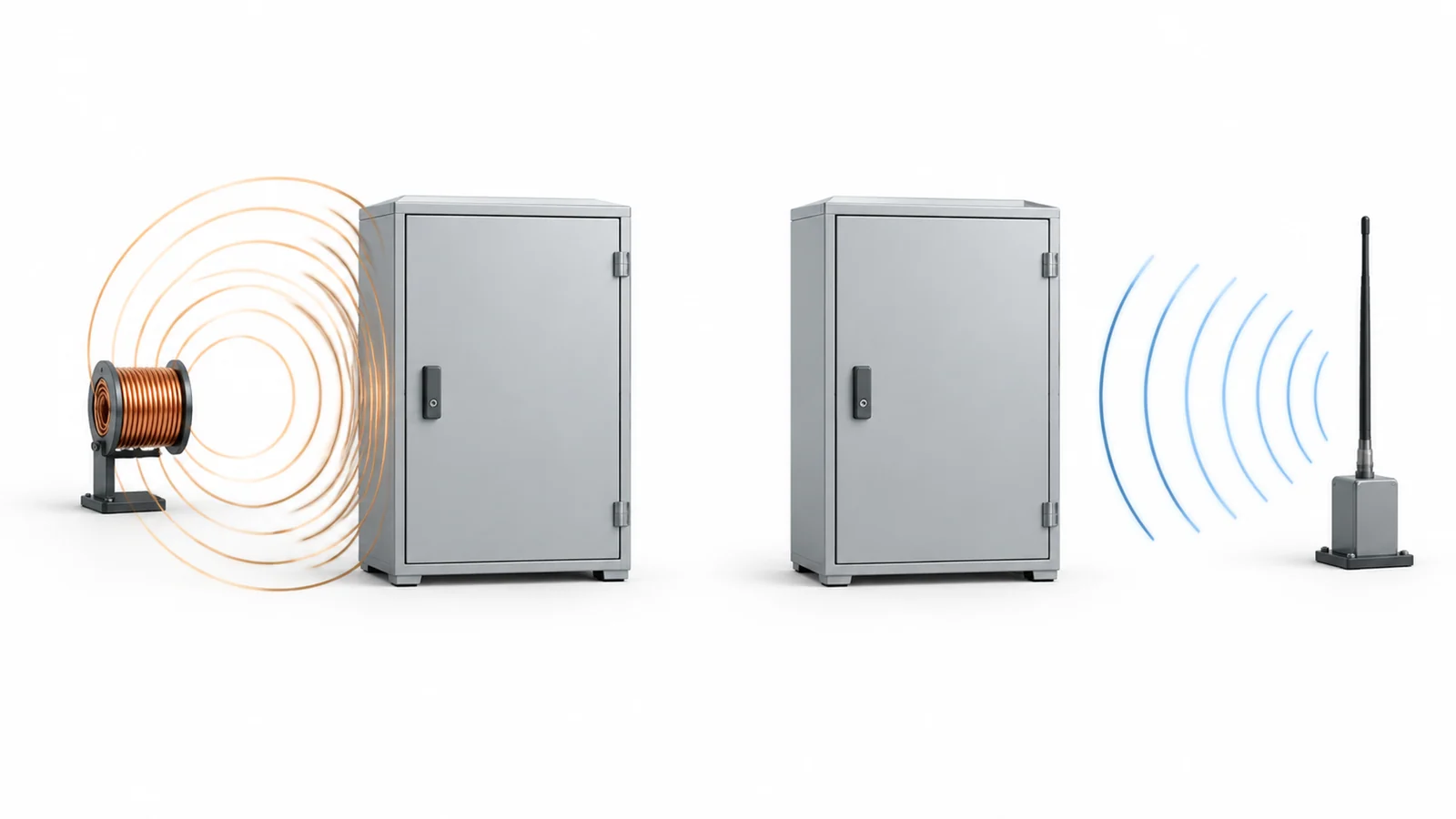
Whether a quotation calls the product an EMI or RFI shielding enclosure, give the supplier these inputs:
- The frequency range and required shielding effectiveness, where an enclosure attenuation requirement has been established.
- The equipment emissions or immunity requirements, including the intended operating modes.
- The installation conditions: nearby sources, enclosure location, cable arrangement and available space.
- The environmental and service conditions, including moisture, corrosive exposure and how often doors will open.
If the project has no defined attenuation target, ask the EMC engineer or test laboratory to establish what the enclosure must contribute. Avoid comparing isolated “up to” dB figures. Shielding effectiveness varies with frequency, field conditions and measurement arrangement; a useful specification identifies the conditions under which the requirement must be met.[33]
Choose the material and its contact surfaces together
Material selection should account for conductivity, magnetic permeability, thickness and construction. These properties affect shielding differently across frequencies. Increasing wall thickness also leaves any leakage through an inadequately treated seam or opening unresolved.[41]
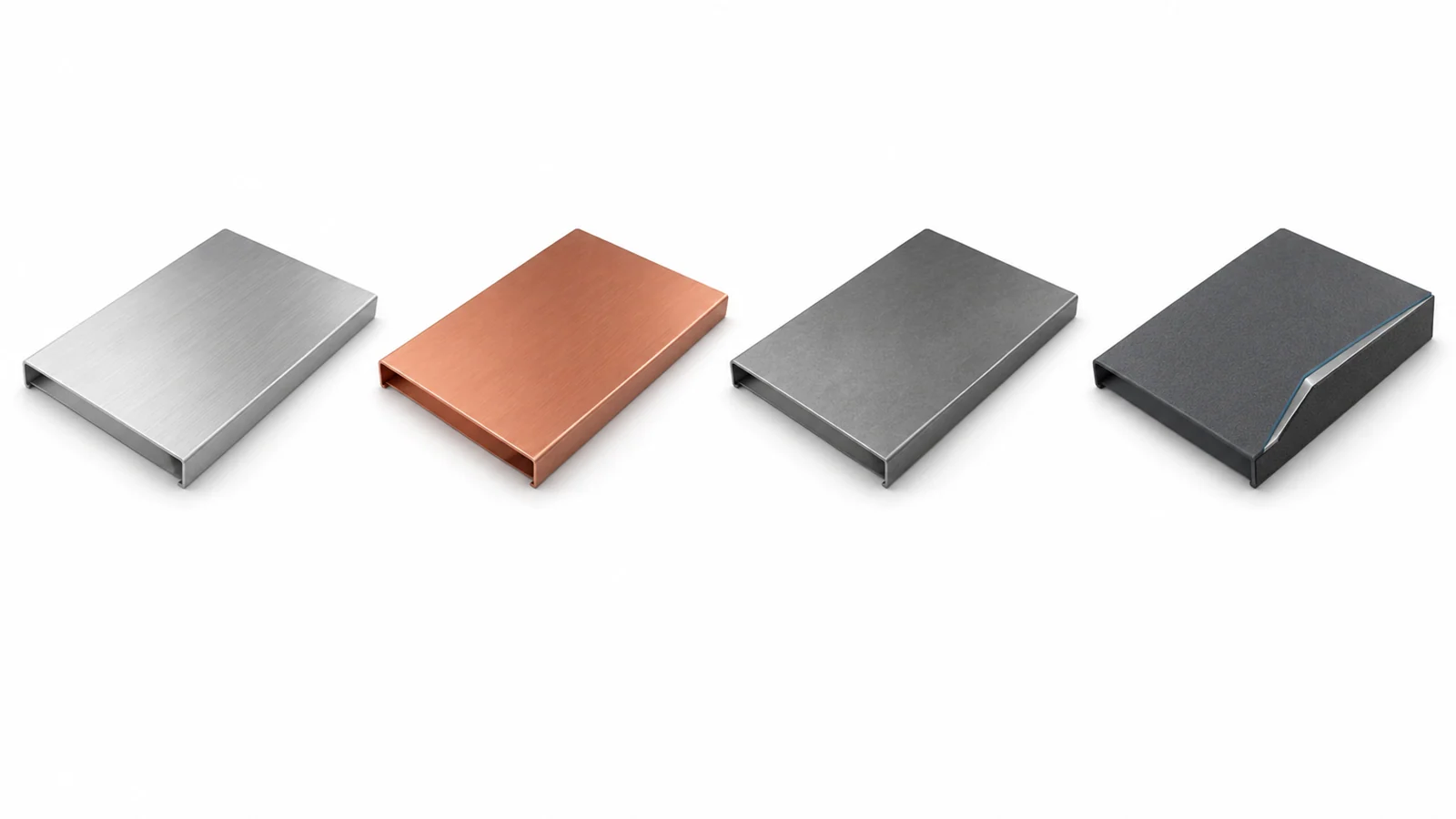
| Construction | What to evaluate before specifying it |
|---|---|
| Aluminum or copper | Assess the conductive wall against the target frequency range, then review how panels, doors and fittings maintain electrical contact. |
| Steel | Check the specified alloy and its magnetic properties. For low-frequency magnetic interference, include geometry and field strength in the assessment. |
| Stainless steel | Identify the grade and required magnetic behavior before making a shielding claim. “Stainless steel” alone is an incomplete magnetic-shielding specification. |
| Plastic with a conductive coating or metallization | Evaluate the conductive layer, its coverage and the contact between coated parts. The coating and assembled interfaces form the shielding structure.[85] |
For an RF design, prioritize continuous contact at joints and penetrations once wall attenuation is adequate. For a low-frequency magnetic problem, require a separate material and geometry assessment before choosing the metal.[34][41]
Put the surface finish on the drawing. Where a gasket or connector flange must make conductive contact, specify the contact area and its finish. Include corrosion compatibility between the gasket and the mating surface. Laird’s gasket corrosion guidance explains why the combination of metals and exposure conditions matters at a shielded joint.[130]
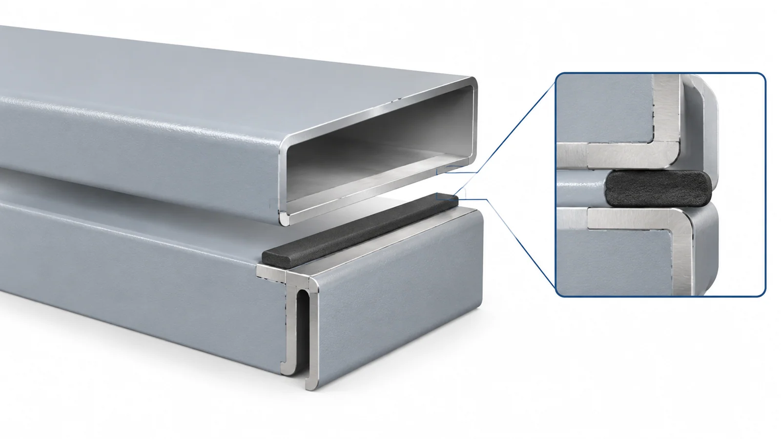
Check doors, removable panels and fixed joints separately
A conductive gasket needs the intended compression along its contact path. Flange flatness, door alignment, latch positions and manufacturing tolerances all affect that compression. Too little can leave an unreliable contact; too much can damage the gasket or accelerate permanent deformation.[173]
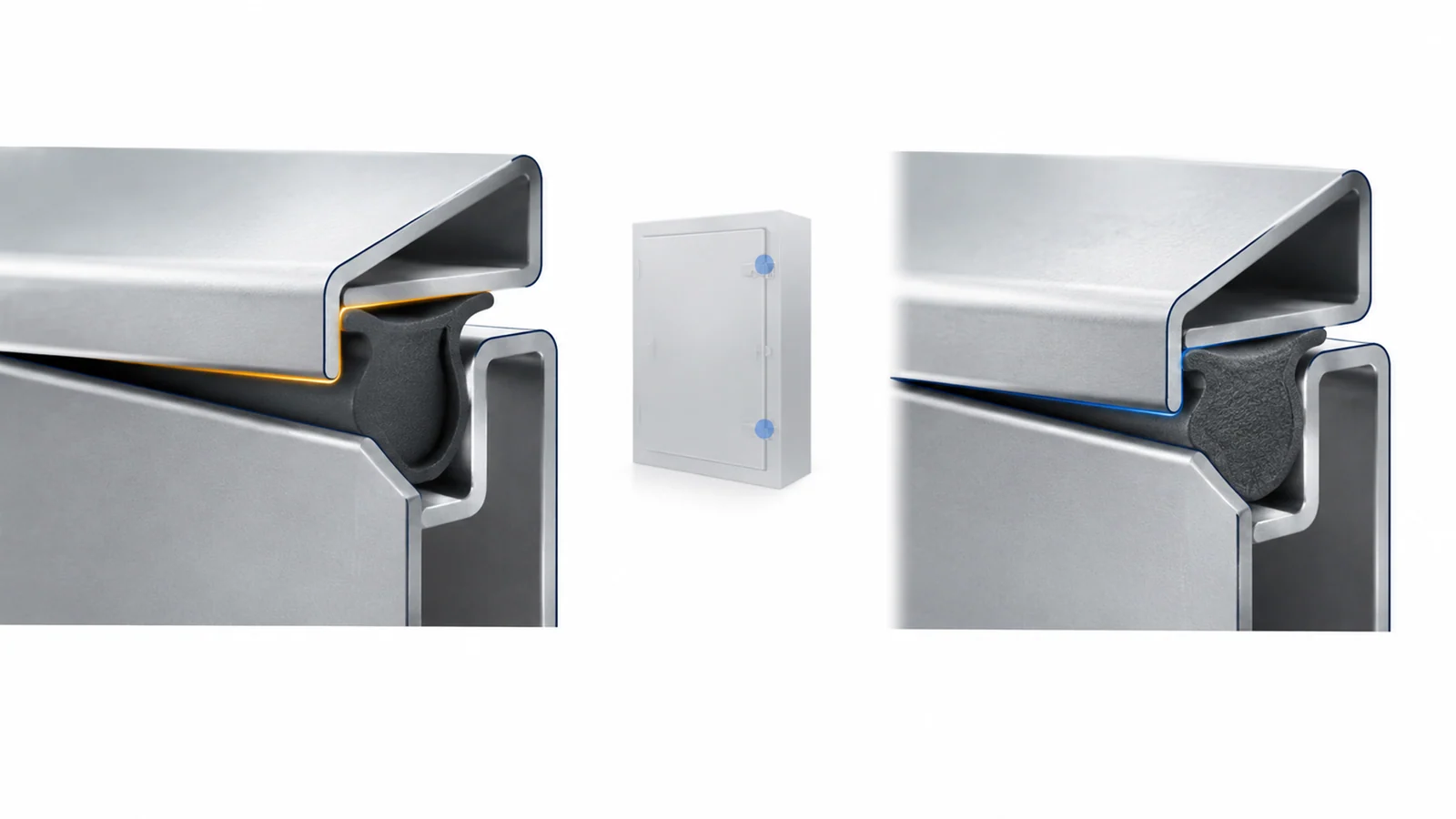
Ask the enclosure drawing and assembly instructions to define:
- The gasket profile and its permitted working compression or deflection.
- The mating finishes and areas that must remain conductive.
- The closure arrangement and available force across the door perimeter.
- The treatment of corners, gasket joints and removable covers.
- The replacement part and inspection procedure after maintenance.
Check the actual door at its corners and between closure points. A gasket selected from a catalog still needs a mechanical arrangement that keeps it within its working range across the full seam.[173]
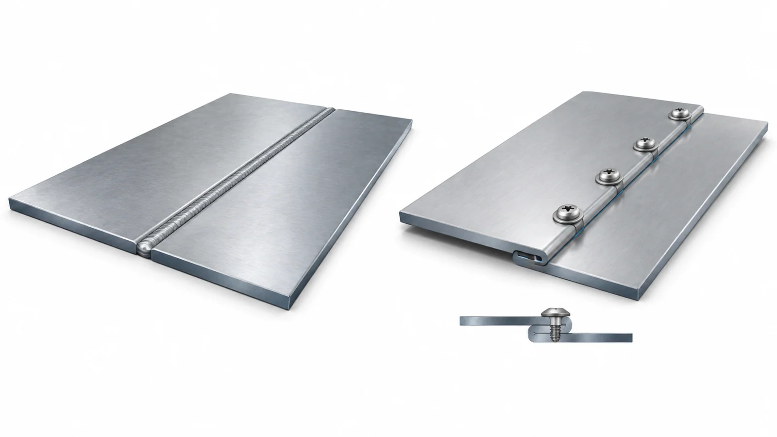
Fixed panel joints need their own review. Welded, overlapping and bolted joints create different conductive paths and remaining openings. For a bolted seam, examine the length of the gaps between contact points, as well as the gap width. Aperture geometry and frequency affect leakage, so a visually narrow seam does not establish its RF performance.[36]
For outdoor or frequently serviced equipment, agree which environmental exposures and opening cycles matter to acceptance. Ask how contact surfaces and gaskets will be inspected afterward, and whether shielding must be retested. Include the exposure sequence and post-test acceptance criteria in the test plan.[130]
Specify the complete ventilation assembly
Honeycomb vents provide depth as well as open area. Their channels can attenuate electromagnetic fields below the relevant cutoff frequency, but performance depends on the cell geometry, material and construction. The vent frame and its contact with the enclosure must also be included in the design.[164]
Request both shielding information and pressure-drop data for the proposed vent. Review them with the fan operating point and the heat load. The design must provide the required cooling with the installed vent, filter and surrounding hardware in place.[46][164]
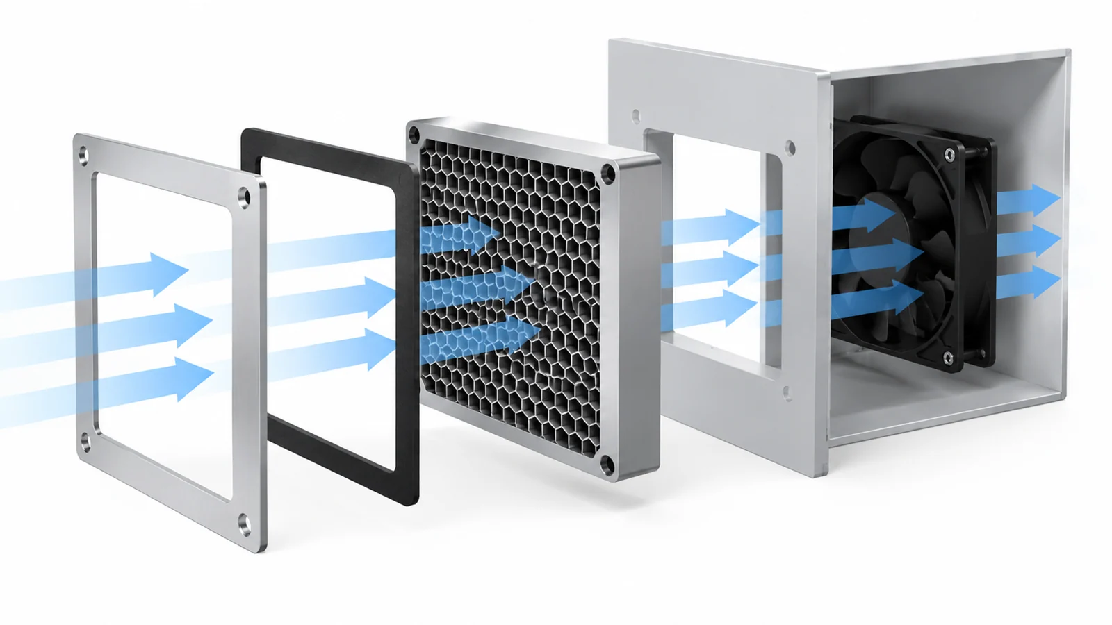
For a mobile ground-radar cabinet, Parker Chomerics describes a custom honeycomb vent with additional conductive and weather sealing. The manufacturer reports environmental and shielding qualification for that vent assembly.[52]
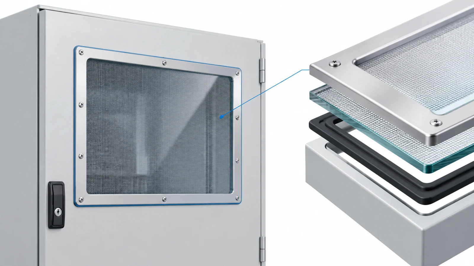
Give display windows and other large apertures the same attention. Identify the shielding treatment and how it connects around the opening, then include that arrangement in the enclosure verification.[34]
Review every cable crossing at the enclosure boundary
A cable passing through a shield can carry interference across the boundary. Closing the space around its outer jacket addresses the physical opening, but the conductor and cable shield still need an appropriate interface with the enclosure.[114]
Prepare an entry schedule covering power, network, signal and antenna connections. For each entry, identify the connector or gland, cable construction and any filtering required by the circuit design.
For shielded cables, review how the shield meets the enclosure at the entry. Where the RF design requires circumferential contact, specify a connector or gland arrangement that provides it and check the flange-to-panel interface. A mechanical cable seal alone does not define that RF connection.[114]
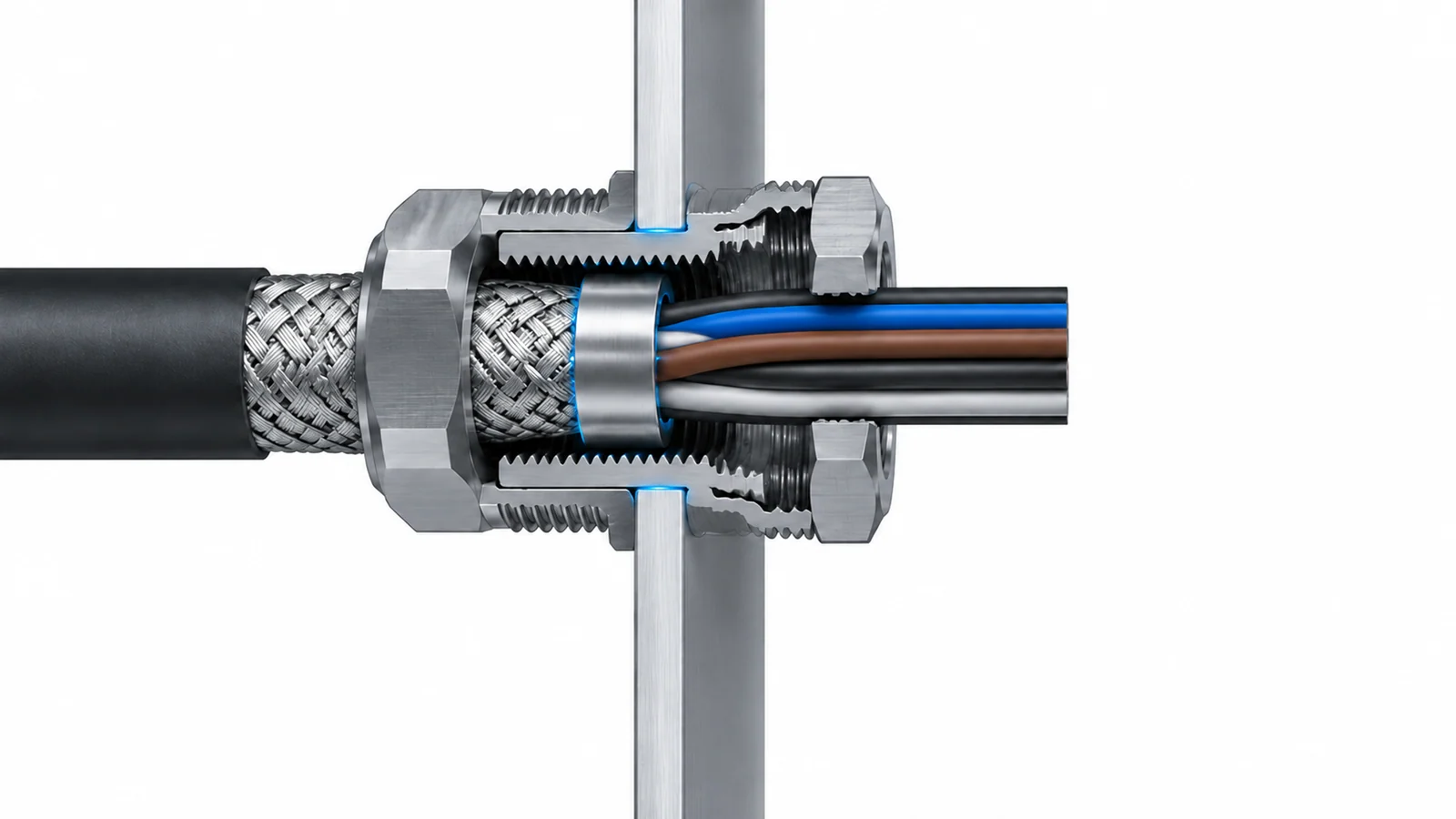
For conductors that need filtering, review the filter’s location and mounting as part of the shielding design. Keep the intended separation between the filtered and unfiltered sides. Stray coupling around a filter can bypass its attenuation, even when the filter itself has suitable component data.[114]
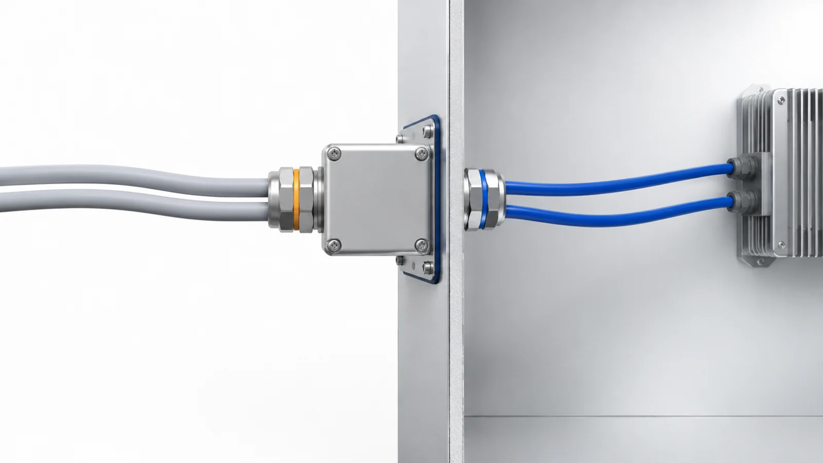
In a published Unit 3 Compliance investigation, the equipment already had an aluminum enclosure, but Ethernet, power and antenna connections provided separate emission paths. The reported corrections included a screened Ethernet bulkhead connector and cable, plus ferrites on other connections. The report attributes the improvement to those combined corrections.[96]
Include unused connectors and spare entry holes in the drawing review. Define their closure arrangement and record whether they were present in the tested configuration.
Match the test report to the configuration you will buy
Supplier evidence becomes useful when its test object is clear. A report for a material sample answers a different question from a report for a complete enclosure. BOPLA explicitly warns that attenuation measured on an empty enclosure cannot be transferred directly to fully assembled electronic equipment.[85]
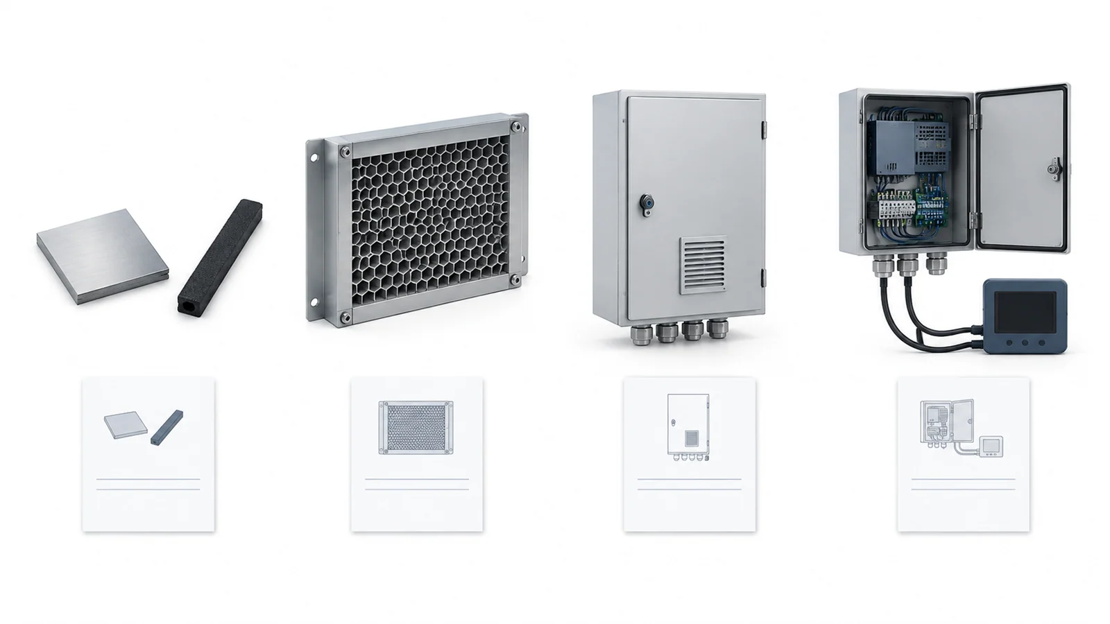
| Evidence supplied | What it can support | What still needs checking |
|---|---|---|
| Material or gasket test | Performance under the stated fixture, frequency and contact conditions | The installed joints, compression and openings |
| Vent, connector or entry assembly test | Performance of that component in its documented mounting arrangement | Its interface with the proposed cabinet |
| Complete enclosure shielding test | Attenuation of the tested enclosure configuration | Changes to fittings, cables, dimensions or assembly |
| Operating equipment EMC test | Results for the tested equipment, modes and acceptance criteria | Whether the delivered equipment and installation match that configuration |
Gasket measurements depend on the fixture and contact conditions. Shielding measurements also need adequate measurement range and a defined reference, so a headline attenuation figure cannot replace the report.[70][71]
Before accepting the evidence, check:
- Sample identity: drawing revision, dimensions, material, finish and component list.
- Assembly condition: door closure, gaskets, vents, windows, connectors and cable or blanking arrangements.
- Method: the test method and edition, frequency range, field type, measurement positions and relevant orientations.
- Results: the measured curve or table, acceptance limits, deviations and any limits imposed by the measurement system’s noise floor.
- Responsibility: who verifies enclosure shielding and who verifies the operating equipment’s EMC performance.
Agree the method with the laboratory before testing. It must suit the enclosure size, frequency range and purpose of the measurement. Have the supplier identify any difference between the tested sample and the quoted configuration.[36][71]
For repeat orders, carry the critical details into production inspection: contact finishes, gasket placement, closure hardware and entry components. Establish a review rule for later changes such as a new cutout, a replacement gasket or a different cable gland.[174]
What to include in an enclosure RFQ
An RFQ should let suppliers quote the same shielding task. Attach:
- A frequency-based shielding requirement, or the equipment EMC requirement from which the enclosure design will be developed.
- The enclosure drawing, including doors, removable panels, fixed joints and all openings.
- A complete cable and connector schedule, including spare entries.
- Material, finish, environmental and service requirements.
- Heat-load and airflow requirements for ventilated designs.
- The proposed verification scope and required report contents.
- Responsibility for shielding components, assembly, testing and later design changes.
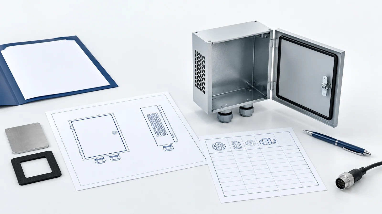
When requesting a custom electrical enclosure, send these requirements with the drawing revision and interface list. Ask the quotation to identify what is included in the mechanical supply, which shielding components are included, and how performance will be verified before design approval.
FAQ
What is the best material for an EMI shielding enclosure?
Choose against the interference frequency and field conditions. Aluminum, copper, steel and conductive coatings can each be suitable in a defined construction. For a low-frequency magnetic problem, assess the specified material and geometry separately. Review the joints and openings before accepting a complete-enclosure performance claim.
Does a metal enclosure provide enough shielding on its own?
The metal walls are only part of the assembly. Door seams, fixed joints, vents, windows and cable entries need to maintain the intended shielding boundary. Ask for evidence that identifies those features in the configuration you will buy.
How should a door gasket be specified for EMI shielding?
Specify the gasket profile, its working compression range, the mating finishes and the closure arrangement. Check contact around the full perimeter, particularly at corners and between latches. A gasket cannot establish consistent contact if the door and flange geometry leave it outside its working range.
Does a honeycomb vent report establish complete cabinet performance?
A vent report supports the tested vent assembly and mounting conditions. Review its frame and perimeter contact with the cabinet, and check pressure drop against the cooling requirement. Include the installed vent arrangement in the enclosure verification.
What needs checking where a shielded cable enters the enclosure?
Check how the cable shield connects to the gland or connector and how that fitting contacts the enclosure panel. Where the design requires circumferential contact, specify that arrangement explicitly. Review filtering separately for conductors that need it.
Does an empty-enclosure test prove that the finished equipment meets EMC requirements?
No. An empty-enclosure shielding test describes the tested enclosure configuration. The operating equipment has its own electronics, cables and operating modes. Agree who verifies enclosure shielding and who verifies the complete equipment against the applicable emissions and immunity requirements.
What should I send with an EMI shielding enclosure RFQ?
Send the drawing revision, frequency-based shielding requirement or equipment EMC requirement, complete interface schedule, material and finish requirements, environmental conditions and cooling needs. Include the proposed test scope and identify who supplies, assembles and verifies the shielding components.
Sources
[33] Introduction to Plane-Wave Shielding Theory
[34] Introduction to Practical Electromagnetic Shielding
[85] BOPLA EMC Brochure
[41] Theory of Shielding and Gasketing
[130] Corrosion of EMI Gaskets
[173] Precision in Practice: Building Reliable EMI/RFI Shielding Systems
[36] Designing an RF Shielded Enclosure
[164] Vent Application and Design Guide TB-1200
[46] Balancing Airflow and EMI Shielding in Electronic Enclosures
[52] Military Ground Radar Manufacturer Required Custom EMI Shielding Vent for Cabinet
[114] Filter Installation Issues: The Synergy of Filtering and Shielding
[96] Networking Equipment – EMC Radiated Emissions Problem Solving – Unit 3 Compliance
[70] Characterization of EMI shielding gaskets up to 40 GHz
[71] Shielding Effectiveness of Gaskets, Composites and Shields
[174] Manufacturing Matters: EMI/RFI Shielding Decisions That Impact Production