
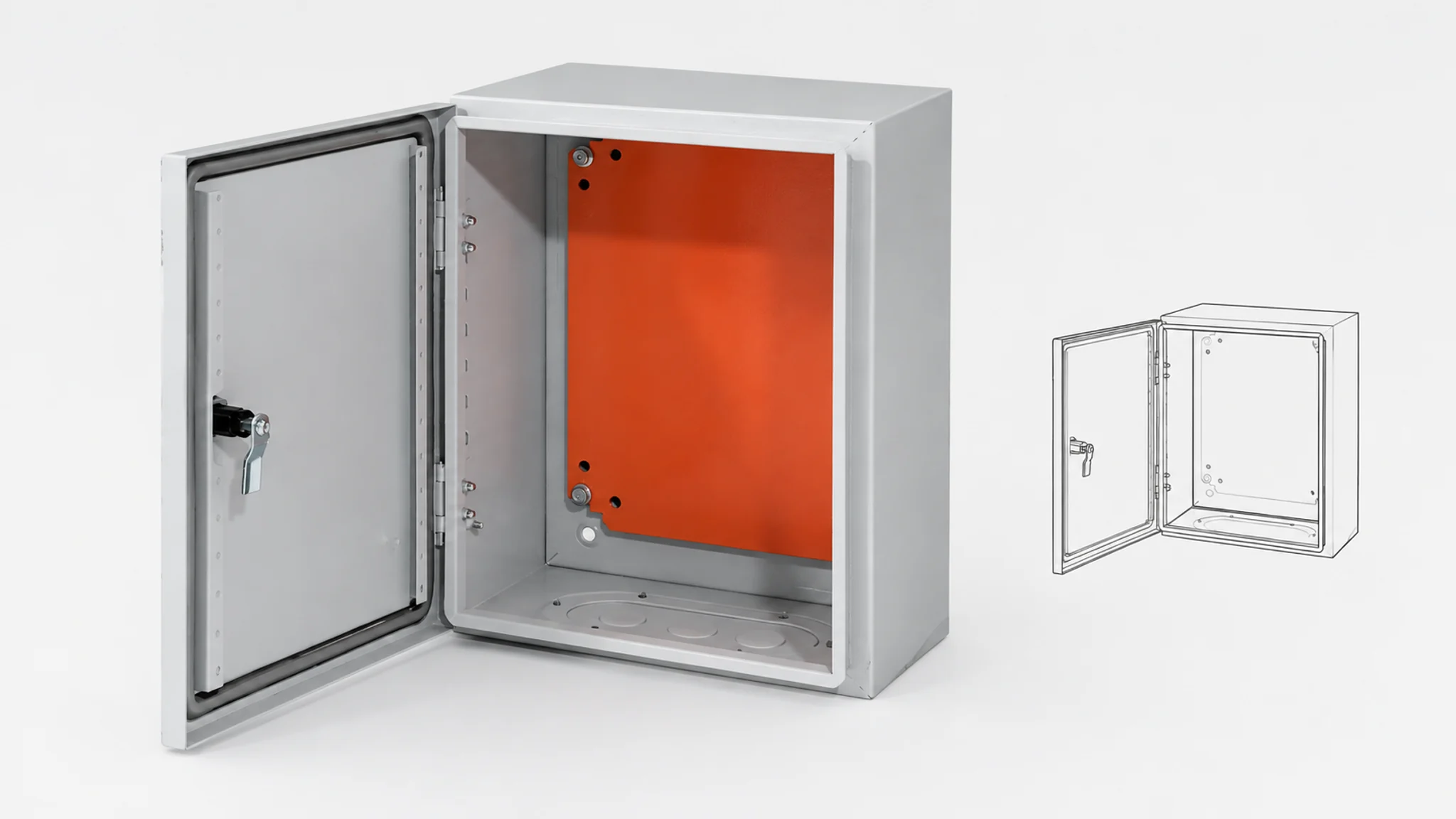

Start your sheet metal enclosure design with the equipment layout and the assembly sequence. Leave room for connected plugs, service tools, bends, and the fit between finished parts. Put those details in the drawing so your fabricator can quote the work and check the interfaces you need to get right.
Use this sheet metal enclosure design guide with your CAD model open. You’ll be able to identify missing dimensions, settle manufacturing questions, and prepare a drawing package that explains how the enclosure should fit together.
Jump to:
- Equipment layout and access
- Thickness, bends and reliefs
- Holes and cutouts
- Datums, tolerances and clearances
- Hardware, joining and finishes
- Drawing package and fabrication review
Define the Equipment Layout and Critical Interfaces
Place the PCB, power supply, terminal blocks, displays, connectors, fans, and mounting hardware before settling on the outside dimensions.
Model the connected plug as well as the connector body. Include the space needed to release its latch and turn the cable. For a board that needs servicing, trace how you’ll undo the screws, disconnect the cables, and lift it out.
| Part of the layout | What to include | What this lets you check |
|---|---|---|
| Internal equipment | Component envelope, fixing points, removal direction | Whether you can install and replace the component |
| Connectors and cables | Mated plug, latch access, cable bend and service loop | Whether the enclosure can be connected in its installed position |
| Tools and fasteners | Screwdriver, wrench and installation-tool approach | Whether you can reach the fixings after adjacent parts are fitted |
| Heat sources | Heat load, inlet and outlet locations, component obstructions | Whether the proposed ventilation has a clear airflow path |
| Lid, door and seals | Opening path, overlap, gasket space and adjacent equipment | Whether the enclosure opens and closes as intended |
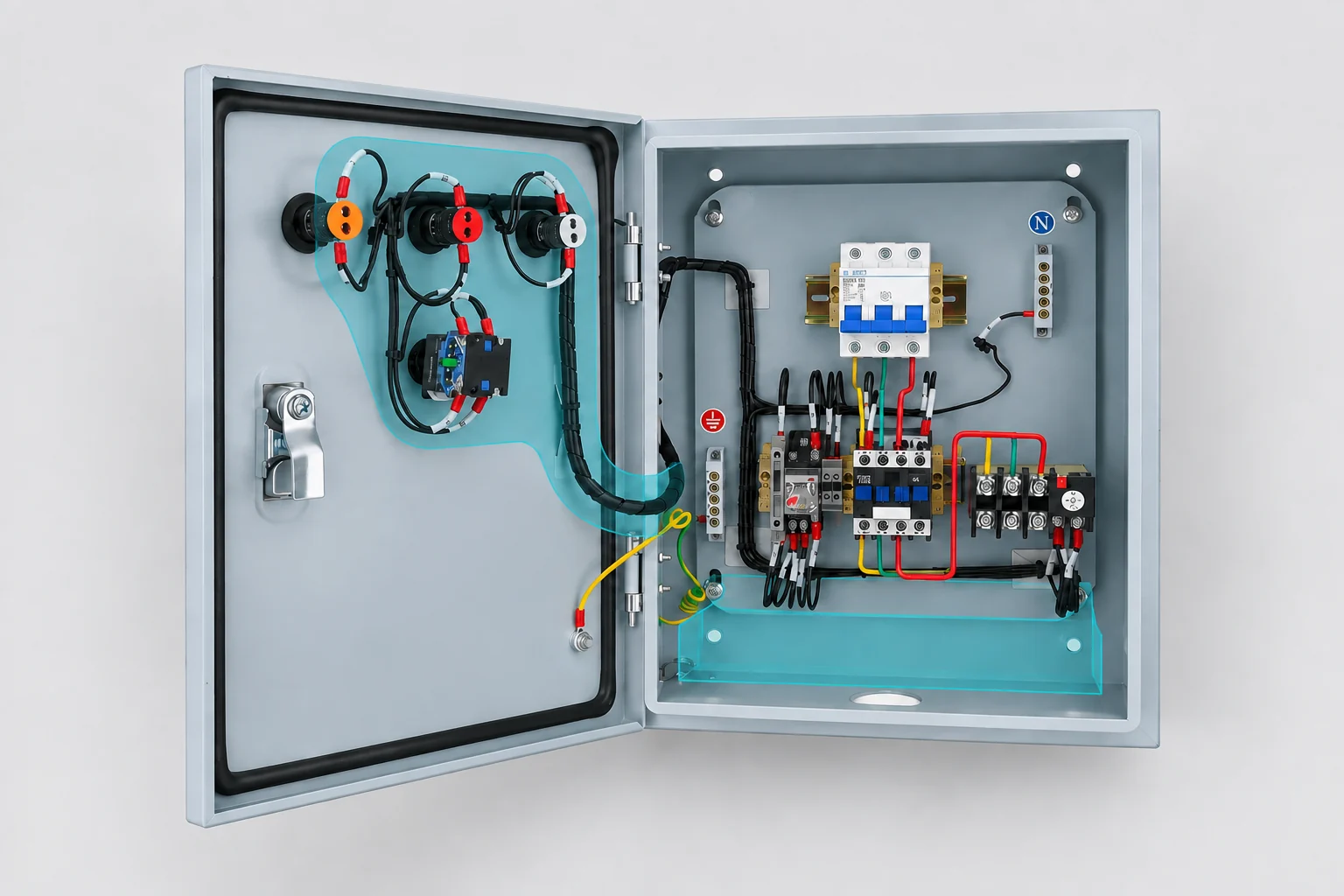
Mark these spaces as keep-out zones in the model. Include grounding points and room for labels or insulation where they’re needed. A marked area gives the fabricator something specific to preserve when reviewing a flange, fixing or cable entry.
If you’re still choosing the overall size, use the electrical enclosure sizing guide to work through usable mounting space and depth.
Coordinate Sheet Thickness, Bends and Reliefs
Choose the material and thickness around the enclosure’s size, supported loads, environment, and weight requirements. Record the material grade and thickness in millimeters or inches so the quote doesn’t depend on interpreting a gauge number.
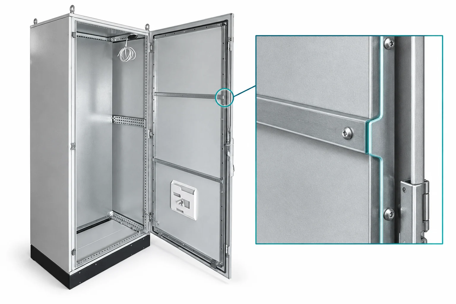
If a wide panel needs more stiffness, consider a return edge, rib or gusset before increasing the thickness of every panel. Approved Sheet Metal’s guide to formed reinforcement explains how these features support sheet metal parts. For a stainless enclosure, the 304 and 316 comparison can help you frame the material discussion around the installation environment.
Give the bend review specific inputs
Your CAD settings affect the flat pattern. Match those settings to the material and forming process before releasing production files. Protolabs’ bend-radius guidance explains how thickness, radius, bend angle and forming method affect bend allowance.
Use this table to prepare the discussion:
| Item | What you provide | What to settle with the fabricator |
|---|---|---|
| Material and thickness | Grade, nominal thickness and relevant load or weight requirements | Stock availability and forming suitability |
| Inside bend radius | The radius shown in the model; identify any radius needed for a mating part | Tooling choice and achievable geometry |
| Flanges and returns | Length, direction and nearby features | Minimum workable flange and tool access |
| Bend sequence | Formed model and areas where access is restricted | An order that allows each bend to be made |
| Bend allowance or K-factor | Current CAD settings, if you’re supplying a flat pattern | The bend data to use for the production flat |
| Flat-pattern ownership | Whether you expect to supply it or need it prepared | Who creates it and which revision is approved |
If the fabricator prepares the flat pattern, give them the formed model and the dimensions that control fit. If you supply it, check it against the agreed bend data. Either route gives you a clear owner for the file used to cut the sheet.
Make room at bend ends
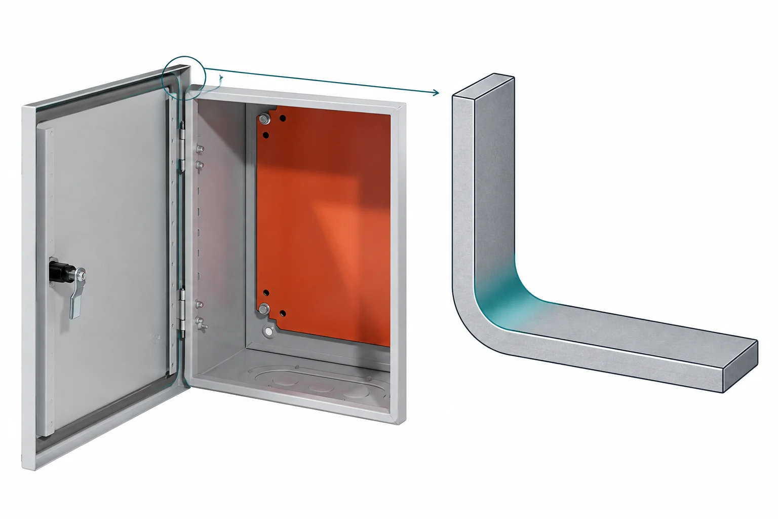
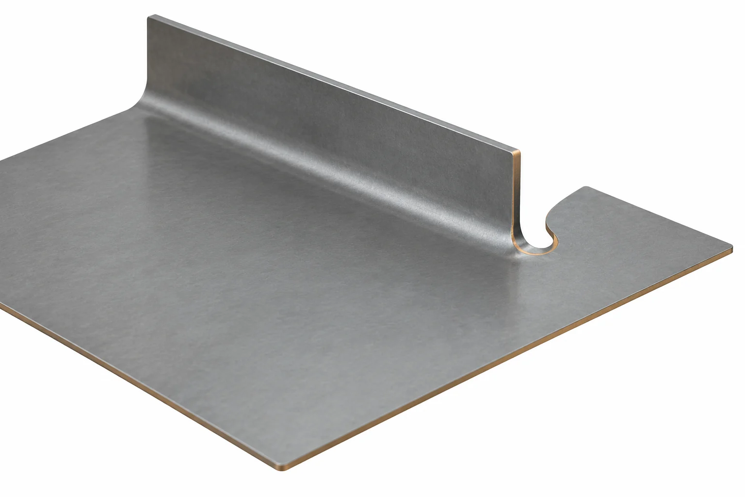
A relief cut gives material room to move where a bend ends near an edge, tab or adjoining wall. Protocase’s bend-relief guide shows how reliefs address tearing, cracking and local distortion.
Show the relief shape in the design and review its width and depth with the chosen material and radius. Where that corner meets a seal or visible edge, include the joining and finish requirements in the same review.
Position Holes and Cutouts Around the Forming Process
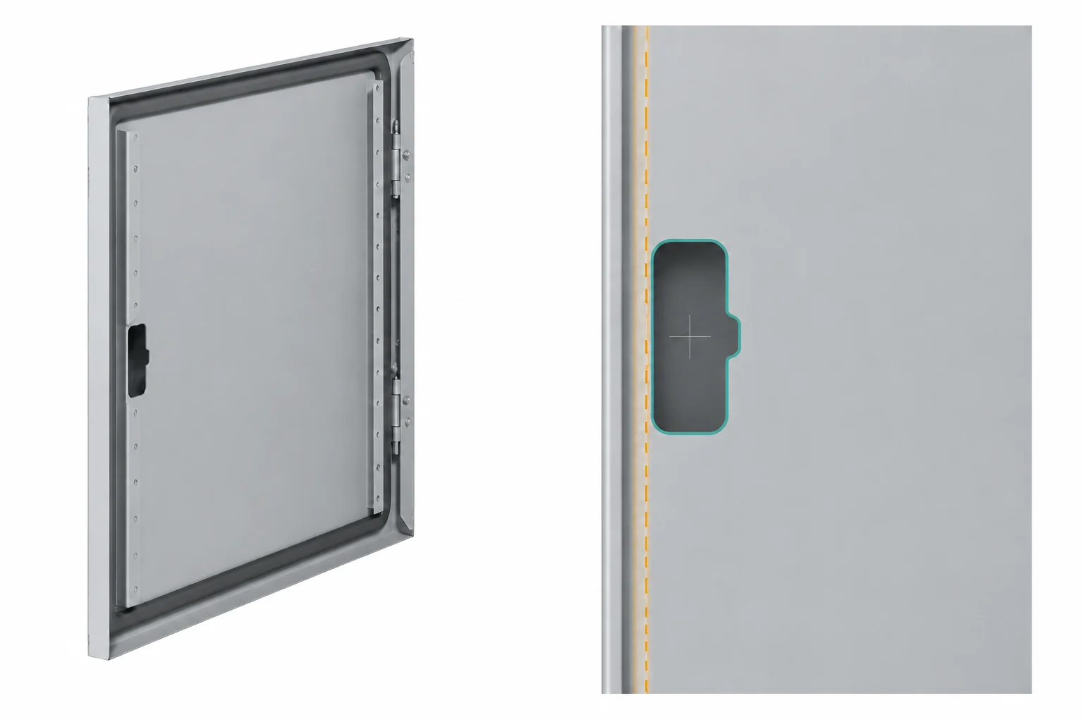
A connector opening needs to hold its shape after the panel is bent. Features close to the forming area can stretch or flare, as described in Protocase’s cutout placement guidance.
For each opening, identify the nearest bend and the dimension that controls its position. State where that dimension starts and ends. A distance from a hole center to a bend centerline is different from the distance between the hole edge and the bend tangent.
Review the opening with the component installed
| Check | What to show or decide |
|---|---|
| Position | Hole or cutout location from the agreed datum, plus its nearest bend reference |
| Forming | Material, thickness, inside radius, and the clearance needed for the selected tooling |
| Component fit | The connector, bezel, gasket or fastener that occupies the opening |
| Installation | Insertion direction and access for the plug, latch and assembly tool |
| Finished condition | Whether the size applies to bare metal or the coated opening |
If the opening is close to a bend, send that detail for review while its position can still change. Ask whether moving the feature, changing the local geometry or using a different manufacturing sequence will give you the required fit. You’ll have a specific decision to resolve before releasing the panel.
Give ventilation a defined job
Locate vents around the heat sources and the intended airflow path. Leave room to fit and replace fans or filters, and state the dust or water exposure the enclosure needs to handle. These are linked decisions: Approved Sheet Metal’s ventilation guide covers airflow alongside component layout and environmental protection.
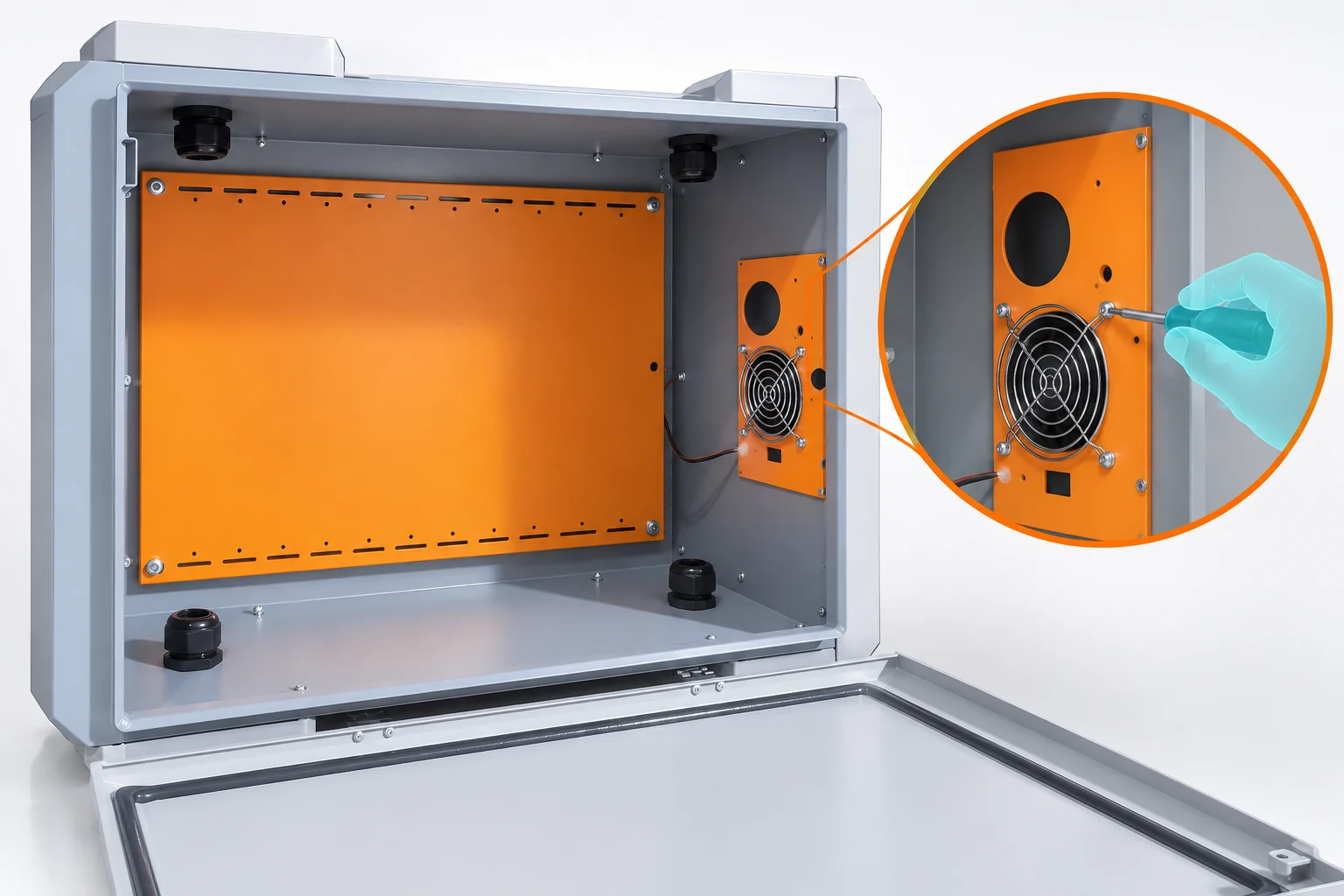
Record who will check the thermal design. That lets the mechanical drawing show the agreed openings while keeping the temperature and airflow questions with the person responsible for them.
Specify Datums, Tolerances and Assembly Clearances
Start with the surfaces and holes that locate the enclosure in use. Use those features to establish the drawing’s datums so related dimensions share a clear reference.
For example, if the enclosure bolts to a machine frame, identify that mounting interface and dimension the related hole pattern from it. If the box slides into a recess, its outside width may be just as important as a connector cutout. Choose critical dimensions by what they do in your assembly.
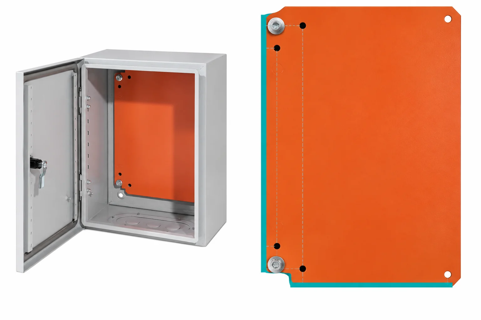
Put specific tolerances on those features, and identify the general tolerances that apply to the remaining manufactured dimensions. Keep dimensions supplied for information clearly marked as reference dimensions. Komaspec’s technical drawing guidance covers how to communicate dimensions, tolerances and manufacturing notes in the drawing package.
Check a mating pair at its limits
Consider a removable cover that fits over two enclosure walls. For this illustrative fit check, compare the smallest permitted cover opening with the largest permitted body width, including the specified finish on the mating surfaces. Then check screw alignment and the cover’s removal path.
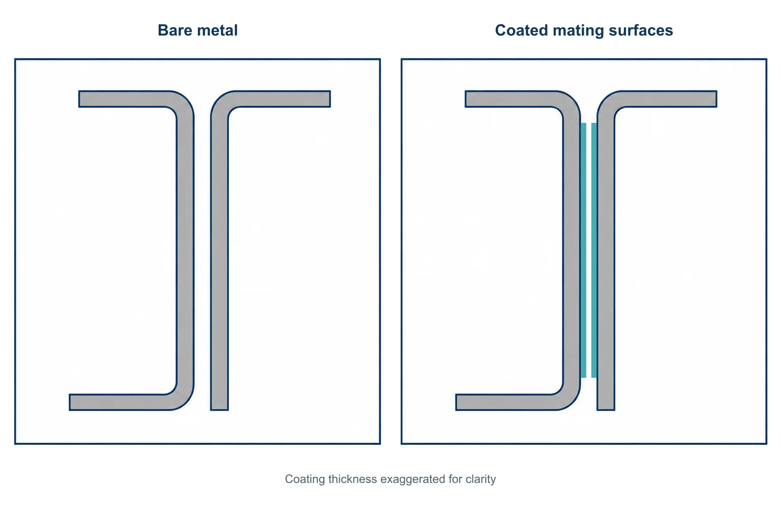
This makes the clearance review concrete. You can see which dimension needs a tighter limit, where more clearance is available, and what to measure on the finished parts. Protolabs’ sheet metal assembly guidance discusses the effect of forming variation and powder coating on mating components.
Call out whether each critical fit is checked after forming or after finishing. For a gasketed lid, include the gasket space and closure condition. For dimensions that cross several bends, agree on the measurement setup so the first article and later parts are checked the same way.
Plan Hardware, Joining and Finish Allowances
A thread size alone leaves several manufacturing questions open. The fastener also needs a suitable hole, enough surrounding sheet, the correct installation direction, and room for the installation tools.
For self-clinching hardware, follow the selected part’s datasheet and PEM’s installation guidance. Put the following in your hardware schedule:
- Manufacturer, part number and thread size.
- Compatible sheet material, thickness range and hardness limits.
- Installation-hole size and minimum edge distance.
- Installation side, tool access and assembly sequence.
- Finish requirements and the inspection or fit check to perform.
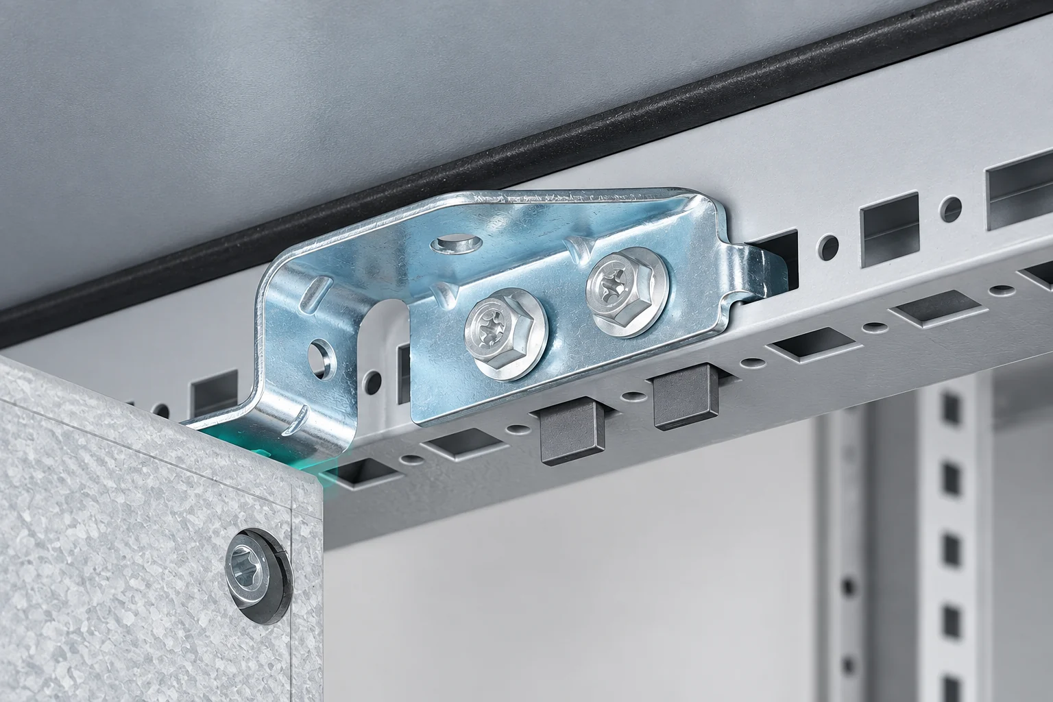
With those details on the drawing, the shop can review the actual fastener you’re using. You’ll also have a clearer basis for checking any proposed substitution.
Choose joints around assembly and service
Use a removable fixing where you’ll need to open or replace a panel. For a welded joint, show the weld requirement and leave access for welding and any subsequent grinding. Riveting, spot welding, adhesives and tabs or slots each need their own access and sequence review.
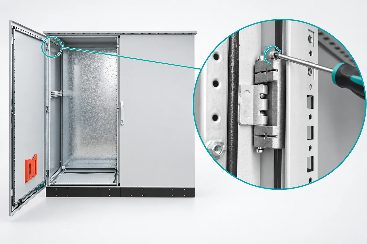
Show how the parts locate before the joint is completed. In Approved Sheet Metal’s Test Devices case study, the teams revised rivet positions and reduced the rivet count. The fabricator also added slot-and-tab connections to help assembly and welding.
Specify the finish where it affects fit
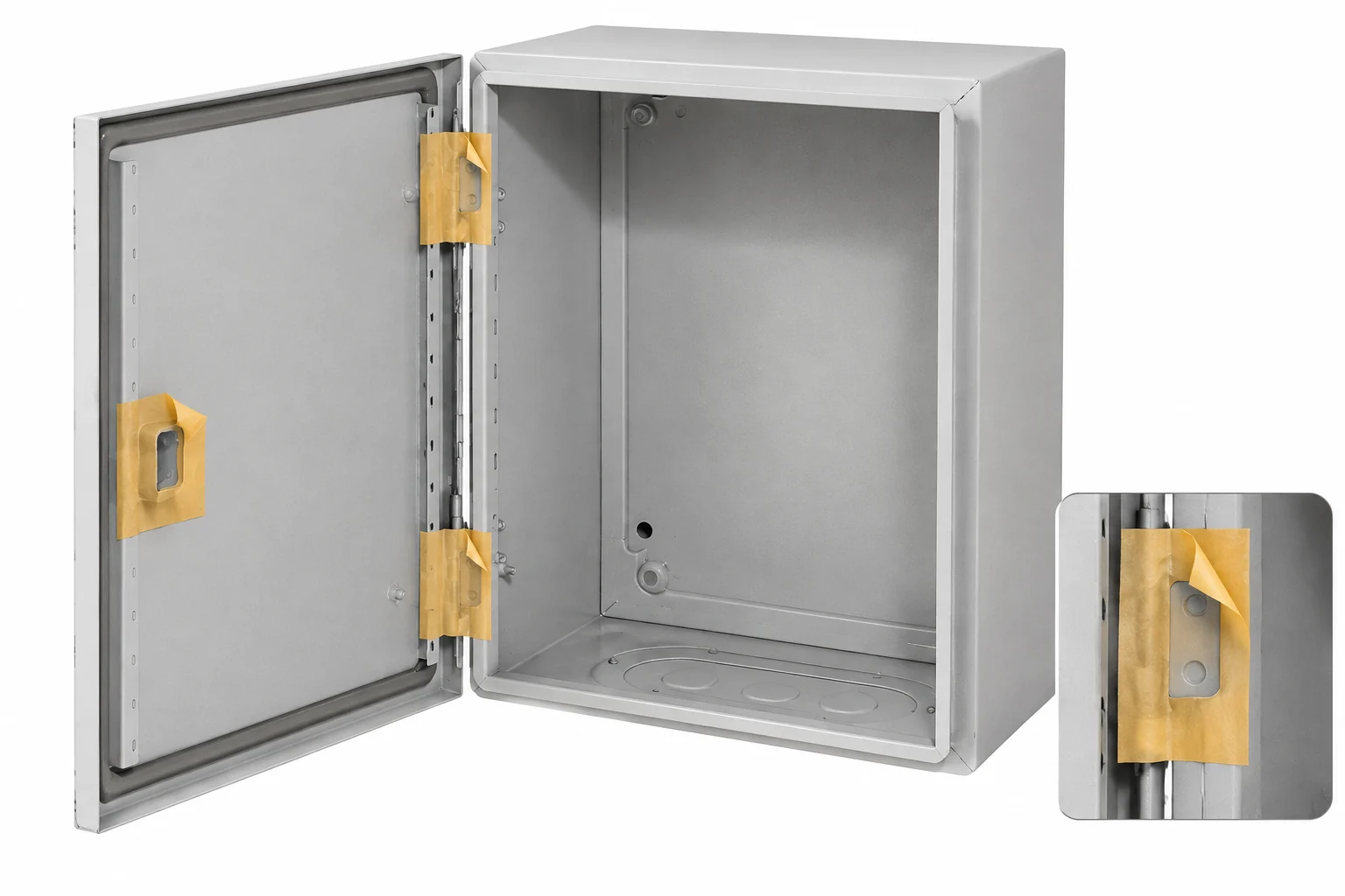
Call out the finish before the part is cut. State the finish type, color or surface appearance, masking areas, and any threads or mating surfaces that need particular treatment. Include grounding or bonding interfaces and cosmetic acceptance requirements.
Coating and surface treatments can change a hole or joint’s final size; Protolabs’ finishing guidance explains why the finish belongs in the dimensional review. Your drawing should make it clear which interfaces must fit after finishing and whether the finish is applied before or after assembly.
Check the Drawing Package Before Fabrication
Use one revision across the model, part drawings, assembly drawing and bill of materials. If you’ve changed a cutout, make sure the matching drawing and hardware details changed with it.
For an initial review, send the best information you have and identify the open questions. Before production release, use the checklist below to close them. Add an owner and a status to each row in your project record.
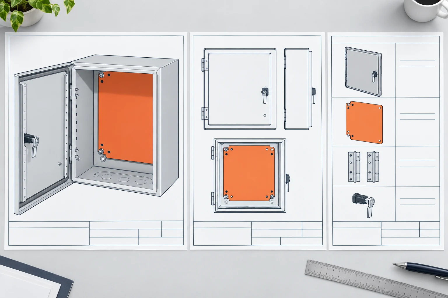
Drawing package checklist
| Review item | Complete when | Suggested owner |
|---|---|---|
| Layout and interfaces | Equipment, connected plugs, mounting, service access and ventilation requirements are defined | Your design team |
| Material and formed geometry | Grade, thickness, bends, flanges and reliefs are agreed | Design team and fabricator |
| Flat pattern | Its owner, bend data and production revision are agreed | Assigned file owner |
| Holes and cutouts | Sizes, locations, corner details and bend references match the components | Design team and fabricator |
| Critical dimensions | Datums, tolerances, finished condition and inspection method are clear | Design and quality teams |
| Hardware and joining | BOM part numbers, installation access, joints and assembly order are defined | Design team and fabricator |
| Finish and appearance | Finish, masking, contact surfaces and cosmetic requirements are recorded | Your team and fabricator |
| Release and delivery | Files share a revision; quantity, approval steps, target date and packaging are agreed | Project and purchasing teams |
Use a test fit to answer the remaining questions
Choose what you want to learn from a first article before ordering it. You might need to check a connector, a lid opening, a mounting pattern or a tool-access problem. An unfinished prototype can answer some geometry questions; coated fits need a check in the intended finished condition.
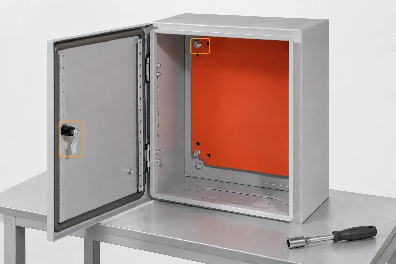
In Approved Sheet Metal’s Gradient Technologies project, test-fitting unfinished prototypes exposed measurements that needed correction before the final parts and a small production run. Carry any measurement changes into the released drawing before ordering the batch.
For custom enclosure manufacturing at FN, you can bring these open questions into the drawing review. Point out the components that must fit, the dimensions your installation depends on, and the details still being decided. That keeps the discussion focused on your assembly and gives the quotation a clearer scope.
FAQ: Sheet Metal Enclosure Design
How close can a hole or cutout be to a bend?
Define the measurement reference first, then review the distance with the sheet thickness, inside radius, feature size and tooling. If the feature is fixed by a mating component, flag that constraint so the fabricator can assess the geometry or manufacturing sequence around it.
Who should create the flat pattern?
Agree on an owner before releasing production files. If you supply the flat pattern, use the agreed bend data and revision. If the fabricator prepares it, send the formed model and the dimensions that control fit.
Should dimensions apply before or after finishing?
State the condition for each critical interface. A cover that must slide over a coated body needs a finished-part fit requirement. The drawing should also identify masking and any surfaces to leave bare.
Can I request a review while the design is still being developed?
Yes. You can start with your current drawing, sketch or specification. Include the dimensions, quantity, installation environment and details you already know, then list what you want to settle during the review.
Send Your Drawings for a Fabrication Review
Send your drawings, enclosure dimensions, material requirements, cutout layout, and quantity for a fabrication review. Add the drawing revision and highlight the interfaces that need the closest attention.
Send your drawings for review. Use the contact form for your project summary, then email the drawing or sketch to the address shown on that page, with your project name in the subject line. If a detail is still open, include it as a question for the review.