

A circuit breaker opens a circuit when its protection mechanism detects an overload or short circuit. For the basic operating sequence, see Eaton’s circuit-breaker fundamentals. It releases the operating mechanism, separates its contacts, and extinguishes the arc that forms between them. In a common low-voltage thermal-magnetic breaker, heat triggers overload protection, while an electromagnet responds to high fault current.
That explains the sequence, but it leaves a question you might recognize: why can a motor start without tripping the breaker, while an overloaded circuit opens a little later? The answer is how much current flows, how long it lasts, and which protection function responds.
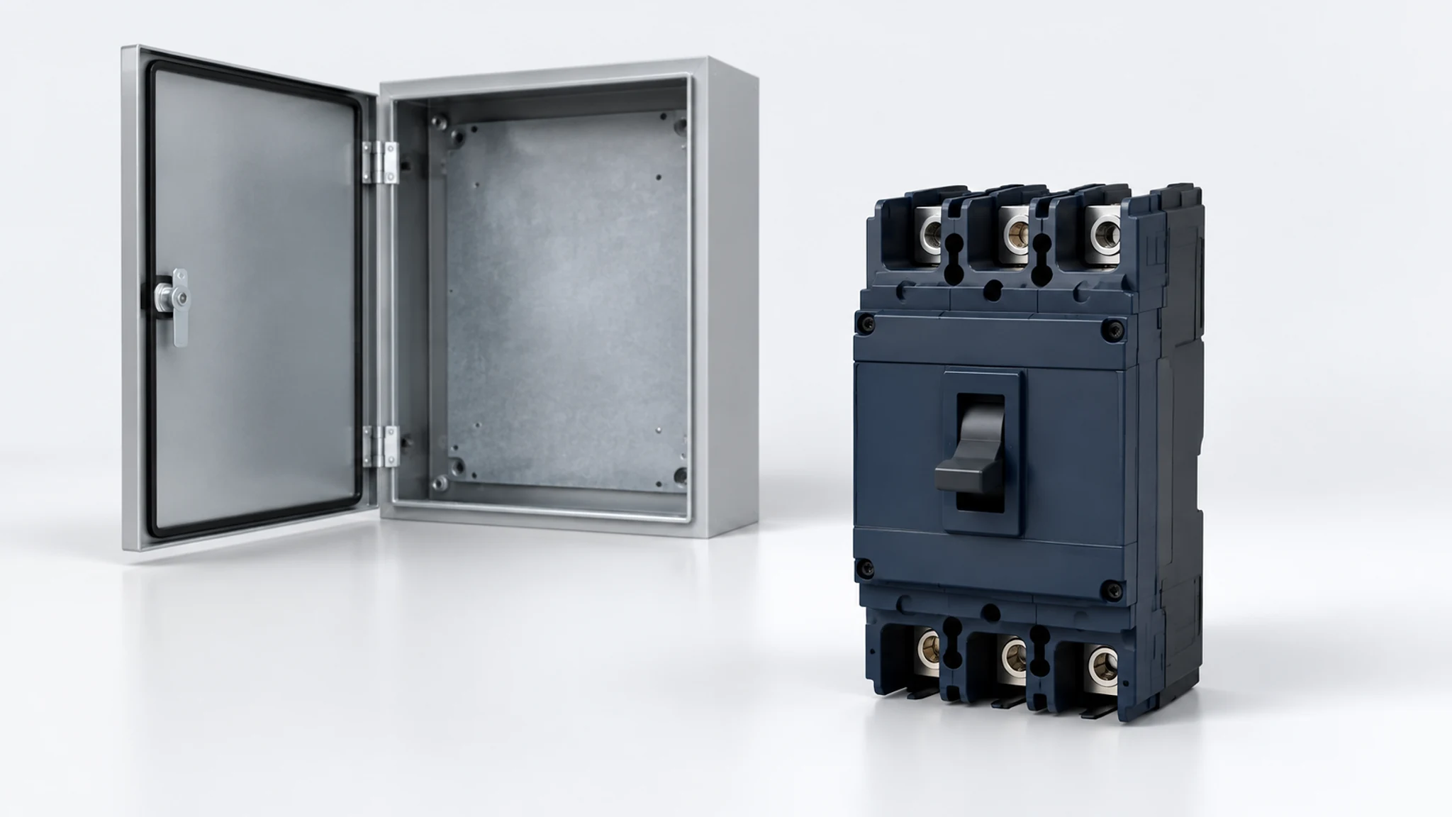
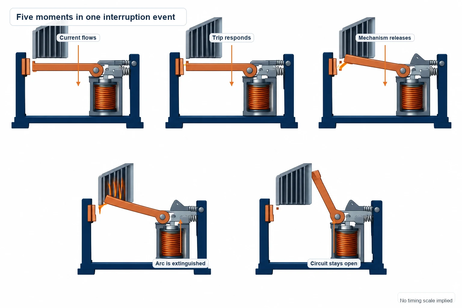
Inside a Circuit Breaker: The Five-Step Operating Sequence
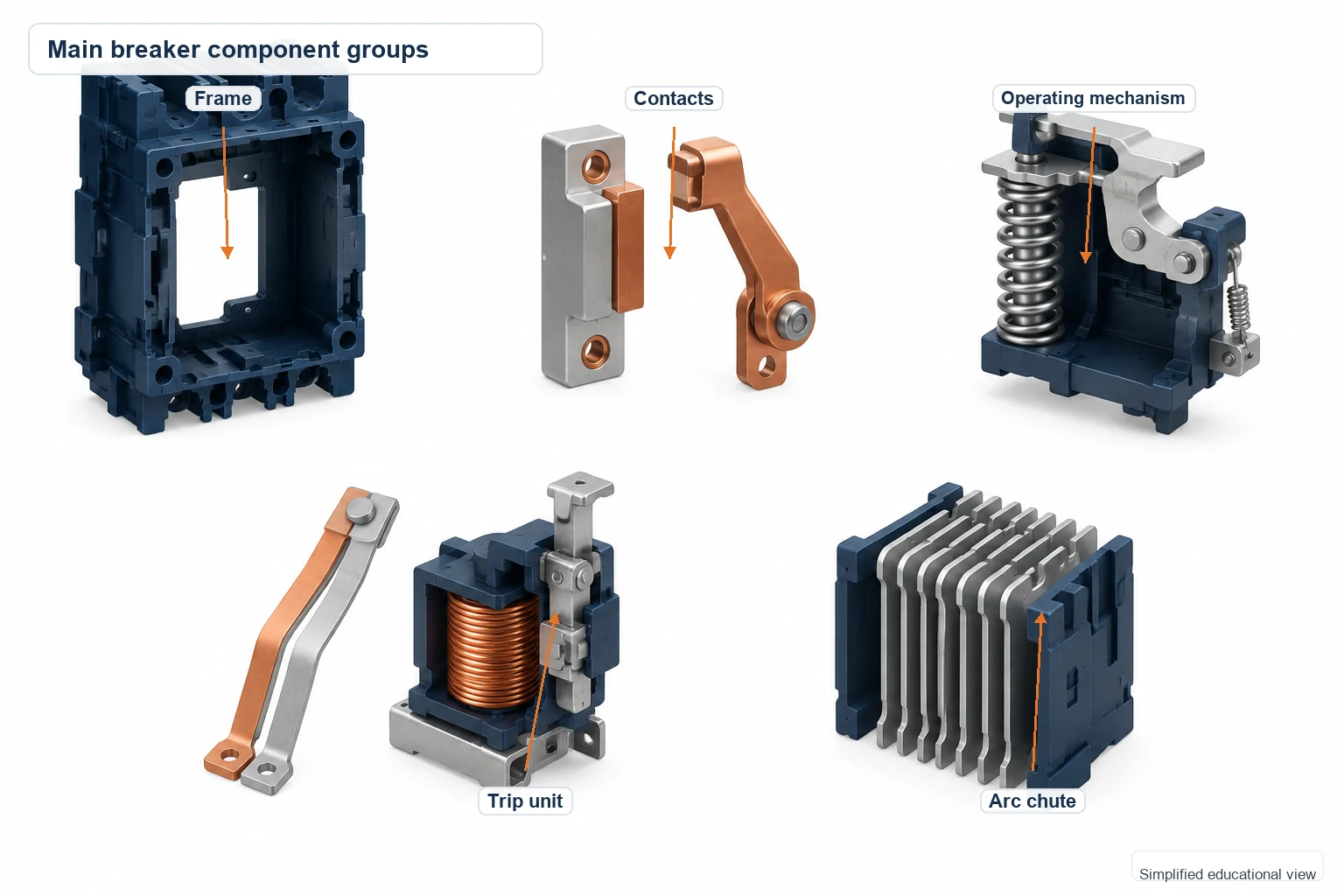
We’ll start with a common low-voltage thermal-magnetic breaker. Its main breaker components are the frame, contacts, operating mechanism, trip unit, and arc extinguisher.
1. Closed contacts carry the load current
With the breaker on, its contacts touch and allow current to pass. The trip mechanism remains ready to respond while the circuit supplies the connected load.
The ampere rating helps you select the device, but its response also depends on time. A short current surge and a sustained overload can produce different outcomes. You’ll find that relationship in the manufacturer’s time-current curve.
2. An overload or fault activates the trip unit
During a sustained overload, heating causes the thermal element to operate. A much higher fault current can activate the magnetic trip. Schneider Electric’s thermal-magnetic documentation shows these as separate overload and instantaneous protection functions.
This gives the breaker two ways to respond: a delayed response to an overload and a much faster response to high fault current. The exact thresholds belong to the specific breaker and its settings.
3. The mechanism releases and the contacts move apart
When the trip condition is reached, the trip unit releases the operating mechanism. Stored mechanical energy drives the opening action.
Think of the trip unit as the trigger and the operating mechanism as the part that carries out the movement. Opening the contacts interrupts the supply path; finding the cause of the trip is the next part of the investigation.

4. The breaker extinguishes the arc
Current can briefly continue across the opening contact gap as an arc. The breaker has to extinguish that arc to finish interrupting the circuit.
Low-voltage breakers commonly use an arc chute. Medium-voltage vacuum breakers use a vacuum interrupter. These are different ways of handling the interruption, which is one reason a breaker’s voltage and interrupting ratings matter alongside its ampere rating.
5. The breaker stays open
After interruption, the contacts remain separated until the breaker is reset and closed. Depending on the design, the handle, a trip indicator, or an electronic record can help you identify its status.
If a breaker keeps tripping, have a qualified electrician investigate before resetting it again or increasing its rating. The cause may be in the load, wiring, connections, protection settings, or the device itself.
Thermal, Magnetic, and Electronic Trips: What’s the Difference?
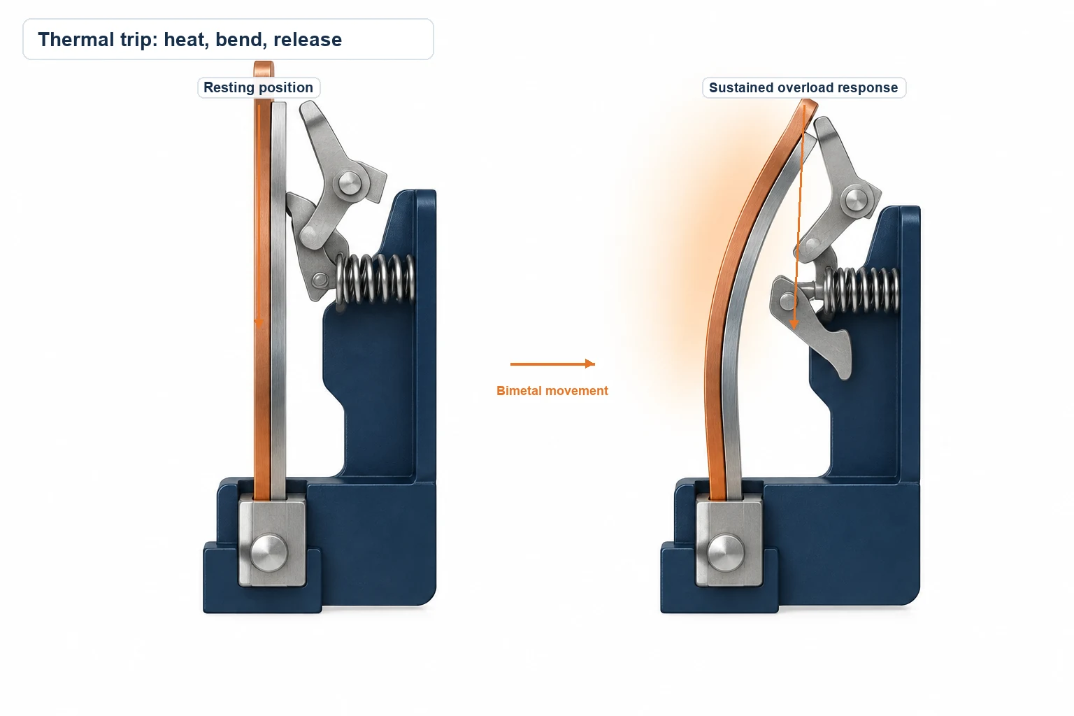
Thermal protection responds to a sustained overload
In a thermal-magnetic breaker, a bimetal heats and bends until it releases the trip mechanism. That takes time. A brief surge may pass, while an overload that continues can cause a trip.
For your project, the useful document is the time-current curve. It shows how current and duration relate to operation, so you can compare the breaker’s response with the load’s starting and running behavior.
Magnetic protection responds to high fault current
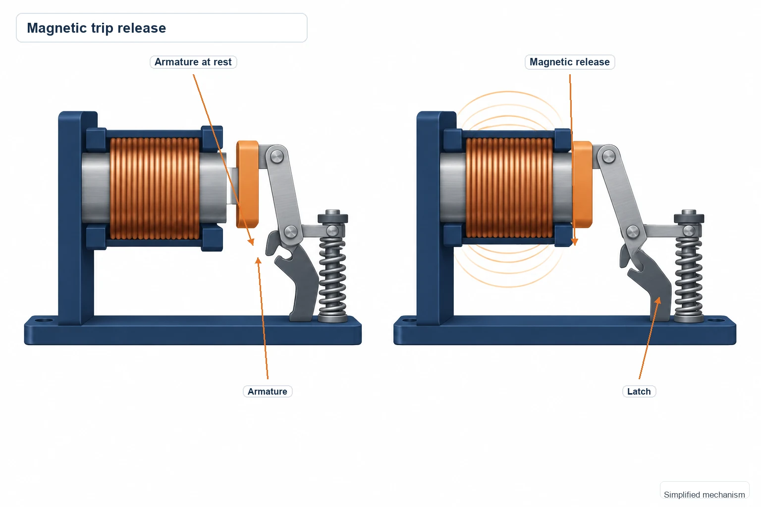
The magnetic element responds to a high current and releases the mechanism much faster than the thermal element. It provides the instantaneous short-circuit protection in a thermal-magnetic design. Pickup levels and AC/DC characteristics vary by device.
Electronic protection compares measurements with settings
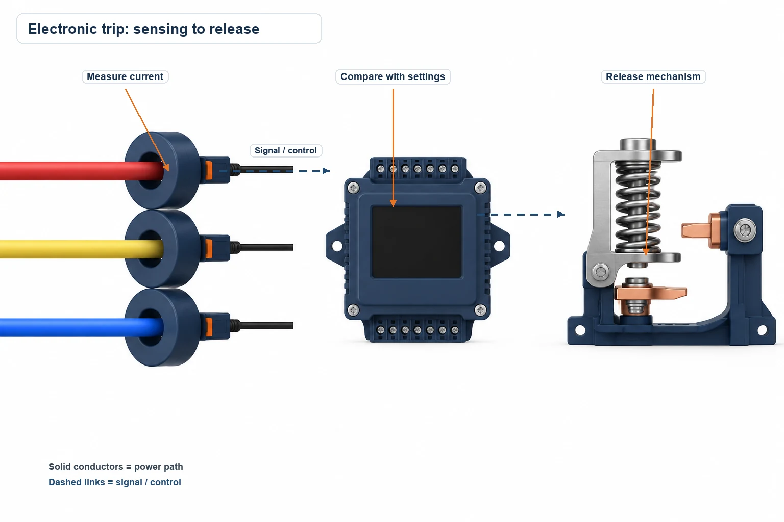
An electronic trip unit uses sensors and control electronics. In Schneider Electric’s documented example, the unit continuously measures current and compares the readings with its protection settings before operating the trip release.
Depending on the model, electronic units offer adjustable protection, diagnostics, monitoring, communications, or coordination features. Some include ground-fault protection. Check which functions come with the exact trip unit you’re specifying.
What Does the Breaker Protect Against?
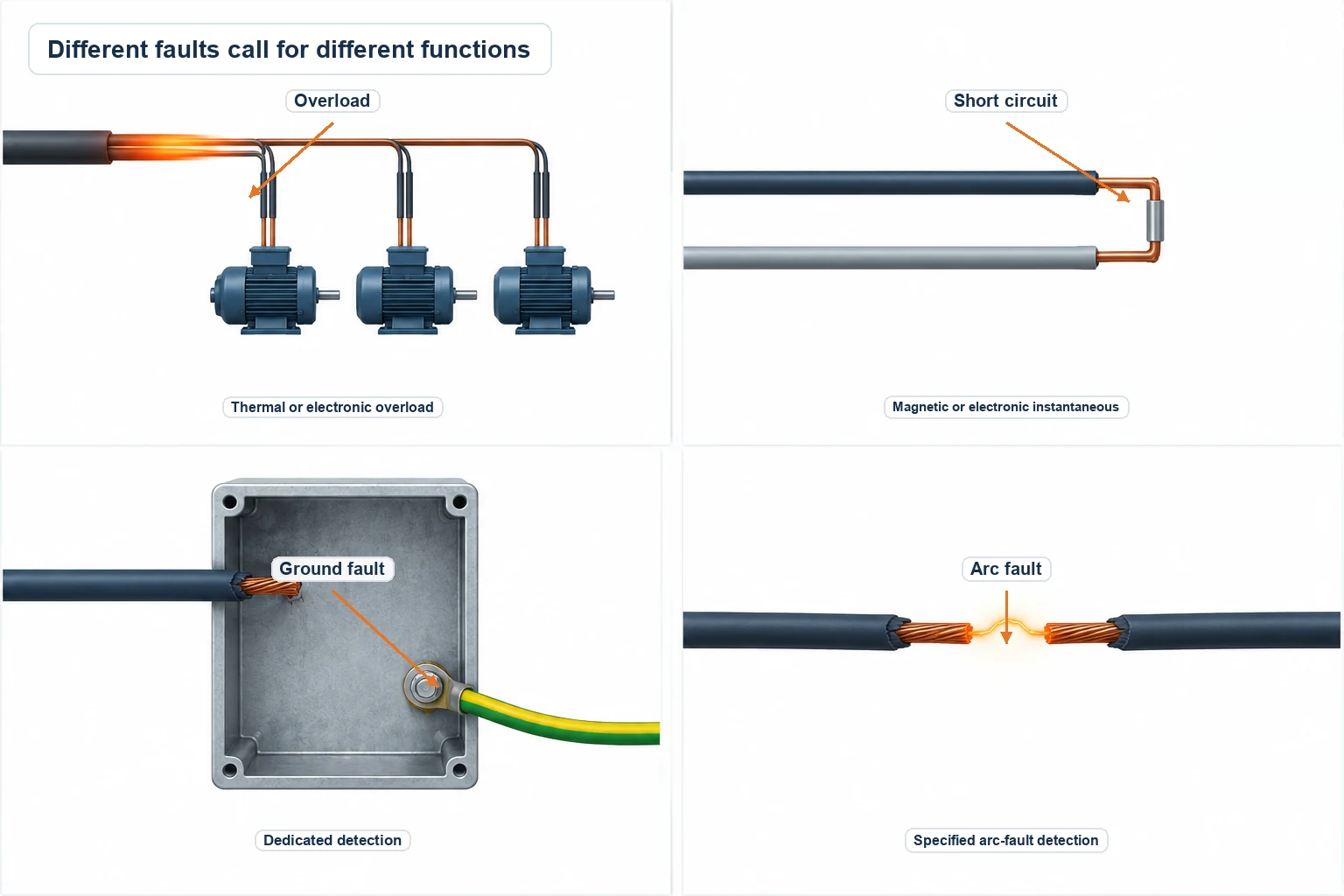
Start with the fault you need to detect, then match the protection function to it.
| Condition | Protection to look for | What to check |
|---|---|---|
| Sustained overload | Thermal or electronic overload protection | Load current, conductor ampacity, and the trip curve |
| High short-circuit current | Magnetic or electronic instantaneous protection | Pickup level and interrupting rating |
| Ground fault | A dedicated ground-fault function or separate protective device | The required detection function and its settings |
| Arc fault | AFCI or another specified arc-fault detection system | The device's stated arc-fault protection function |
Thermal-magnetic overload protection, ground-fault detection, and arc-fault detection are different functions. A historical CPSC recall notice makes that distinction clear: the affected AFCIs could still function as ordinary circuit breakers while an electronic component failure prevented arc-fault detection. The recall concerned specific products, not every AFCI.
For conditions such as overvoltage or undervoltage, identify the additional protection or control equipment your design needs. You can then give the supplier a clear list of functions instead of relying on the general description “circuit breaker.”
Why Doesn’t a Breaker Always Trip as Soon as Current Rises?
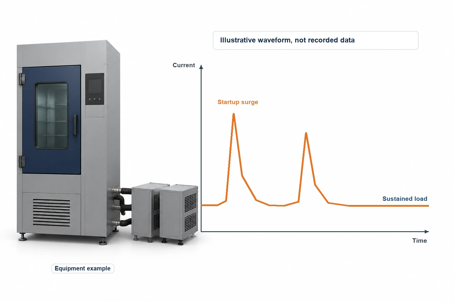
Imagine watching a compressor start. The current rises, then settles toward its running level. The question is whether that current crosses the breaker’s trip characteristic for long enough to operate it.
Fluke investigated a temperature chamber connected to a 120 V, 20 A branch circuit. Its dual-compressor startup produced a peak of 49.7 A, followed by a sustained load near 25 A. The breaker didn’t trip during every recorded event. The investigation identified the chamber as the overload source and called for a dedicated branch circuit sized for the equipment.
That case gives you a useful way to frame a trip investigation: what was running, how high did the current go, and how long did it stay there? Compare that information with the breaker curve before deciding whether the device is unsuitable or the circuit is overloaded.
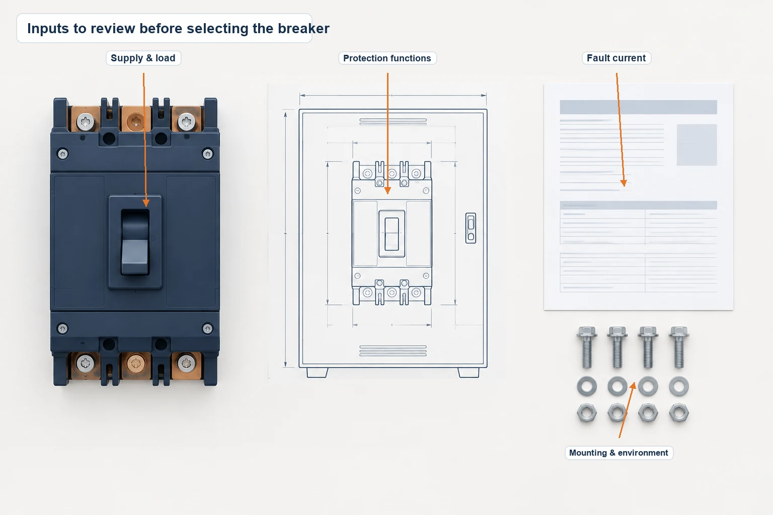
What Should You Check Before Choosing a Breaker?
The electrical designer needs the supply and load information. The panel builder also needs the physical details. Bringing those together early lets you work on the enclosure layout with the actual device in front of you, at least on the drawing.
| Project detail | What you need to establish |
|---|---|
| Supply voltage, frequency, and AC or DC | A device rating suitable for the circuit |
| Running current and startup behavior | A trip characteristic suited to the load while protecting the circuit |
| Conductor ampacity | Appropriate overcurrent protection for the wiring |
| Available fault current | Sufficient interrupting capacity at the installation point |
| Required protection functions | The right trip unit and any additional protective devices |
| Upstream and downstream devices | Protection settings and coordination |
| Poles, terminals, and mounting | Compatibility with the panel, conductors, and accessories |
| Installation environment | Temperature, moisture, dust, corrosion, and enclosure requirements |
The manufacturer’s markings and installation documents supply the device-specific ratings, terminal information, and application conditions. Keep those documents with the project drawing so the people selecting, mounting, and wiring the breaker are working from the same information.
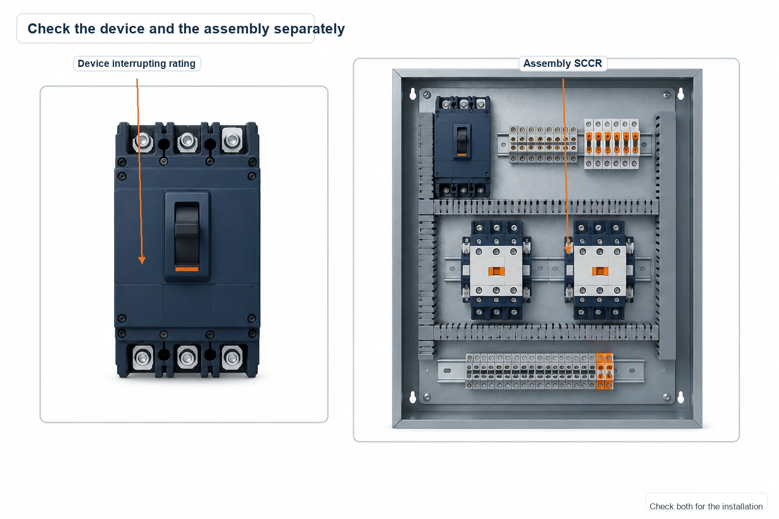
Check the panel SCCR separately
A breaker’s interrupting rating describes the fault current that device can interrupt. The panel’s short-circuit current rating, or SCCR, depends on the assembly and its components.
In an Eaton Bussmann case study, several components limited a Viking Masek packaging panel to 5,000 A SCCR. Component substitutions, including a fused protection solution, raised the overall panel rating to 65,000 A.
So ask for the panel rating as well as the breaker rating. A high-rated breaker on the bill of materials doesn’t automatically give the complete assembly the same SCCR.
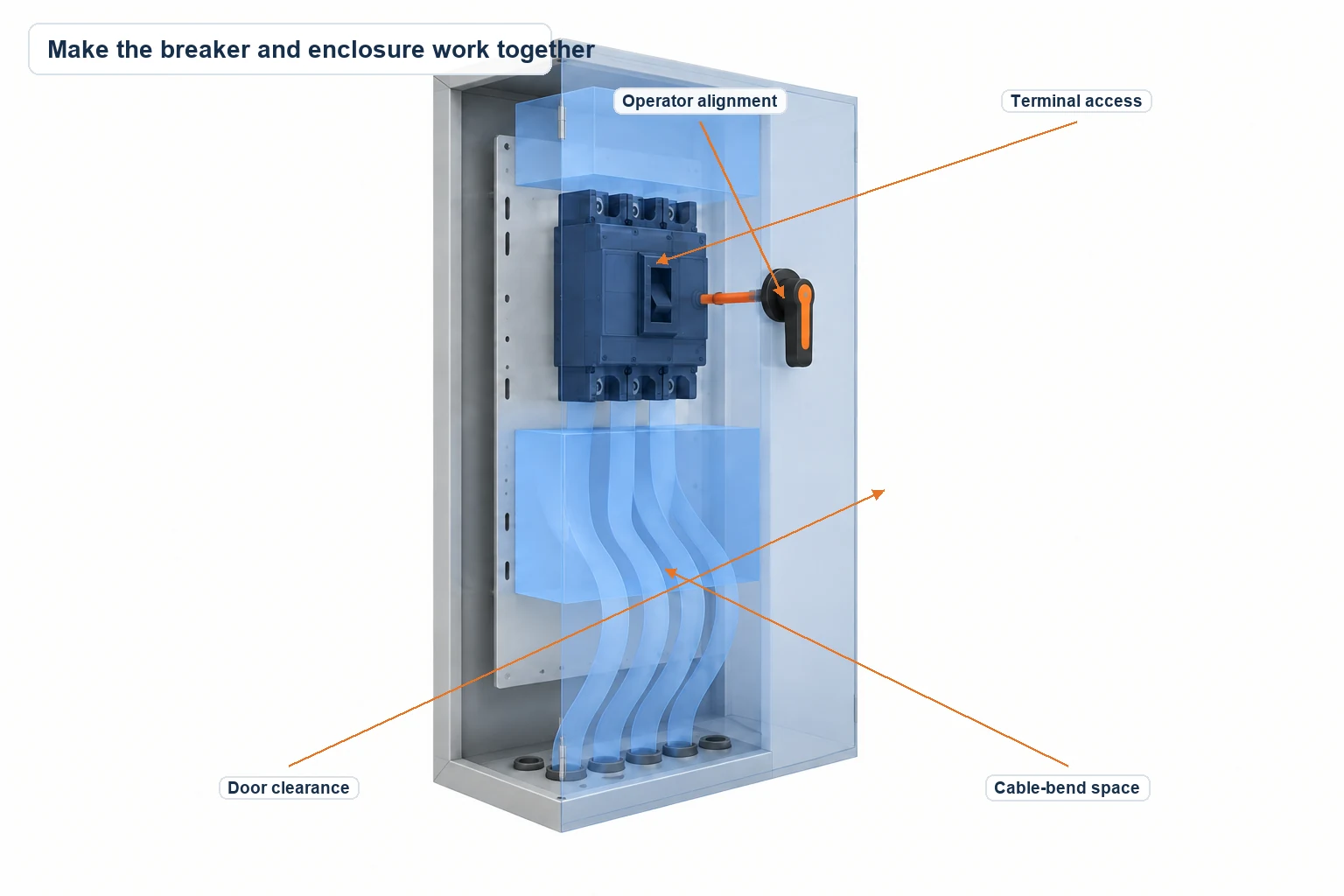
Making the Breaker and Enclosure Work Together
Once you’ve selected the breaker, the questions become physical. Can you reach the terminals? Is there room for the cable bends? Where does the door-mounted operating handle need to sit?
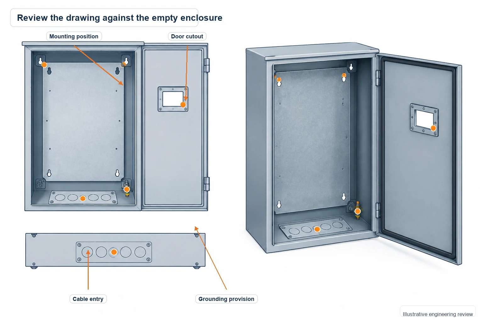
Put those details on the enclosure drawing:
- Breaker model, mounting points, and mounting-plate position.
- Terminal access, cable-entry direction, and wiring space.
- Handle cutout, operator arrangement, and door clearance.
- Grounding provisions and the specified mechanical accessories.
- Space and openings for the thermal-management arrangement selected by your electrical designer.
Our electrical enclosure sizing guide helps you work through usable space, wiring access, and depth. For projects with a defined cooling arrangement, the enclosure cooling guide explains the factors to review with the system designer.
What you get when FN builds to your drawing
At FN Enclosure, we manufacture the enclosure body and mechanical features to your approved drawings. You can specify the dimensions with your mounting layout and cable routes in mind. Your electrical designer selects the breaker and protection scheme; we review and fabricate the cabinet from those requirements.
Before fabrication, we review the drawing and bill of materials. You can compare the mounting-plate position, door cutouts, grounding studs, and cable entries with your device information while changes are still on paper.
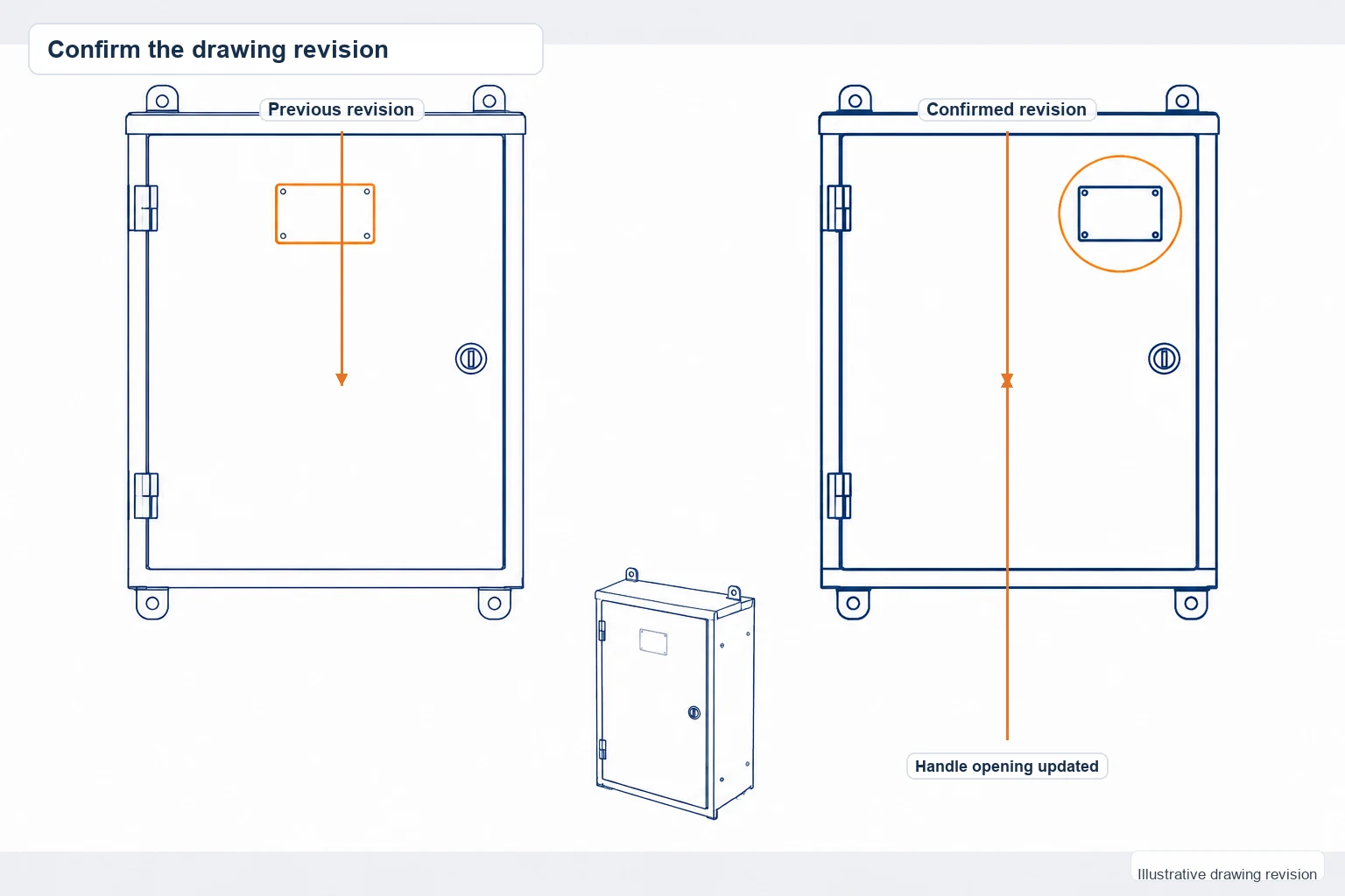
If a handle opening or mounting position changes, we confirm the revision in writing. The approved drawing becomes the reference for manufacture and inspection, giving your purchasing team and panel builder a clear record of what was ordered.
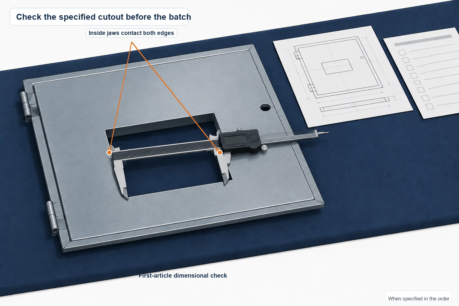
Need to check a first unit before the batch goes ahead? Include first-article approval in the order. Batch production then follows that approval, giving you a checkpoint for the specified dimensions and mechanical interfaces.
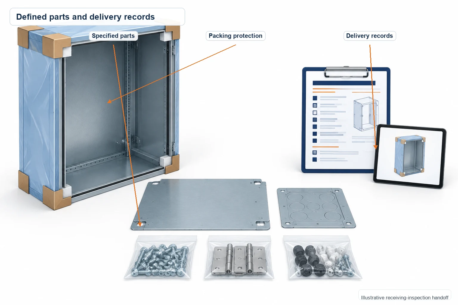
Your quotation and bill of materials define the enclosure parts, hardware, and any optional DIN rails or gland plates. Final inspection records, packing photos, and labels support the shipment, so your receiving team has information to compare with the order when the enclosures arrive.
You can see how this works on our custom electrical enclosures from drawings page.
Circuit Breaker FAQs
What is a circuit breaker?
It’s an electrical switching device that can automatically interrupt a circuit when a defined fault condition occurs. Unlike a fuse, which normally needs replacement after operating, a breaker can usually be reset after the cause has been investigated.
Can startup current trip a breaker?
Yes. A short startup surge can cross the instantaneous pickup level, while a longer event can reach a time-delayed trip characteristic. Compare the startup current and duration with the manufacturer’s time-current curve.
Does an electronic trip unit include every protection function?
The functions depend on the model. Confirm the overload, short-circuit, ground-fault, monitoring, and communication features you need against the selected trip unit documentation.
What should I send for a breaker enclosure quotation?
Start with the breaker model or datasheet and your layout drawing. Add the required enclosure dimensions, operating-handle details, cable-entry locations, installation environment, quantity, and any inspection documents you need.
Send your drawing to FN Enclosure for an enclosure review. We’ll use the drawing and device information to review the mechanical requirements and define what is included in the quotation.