
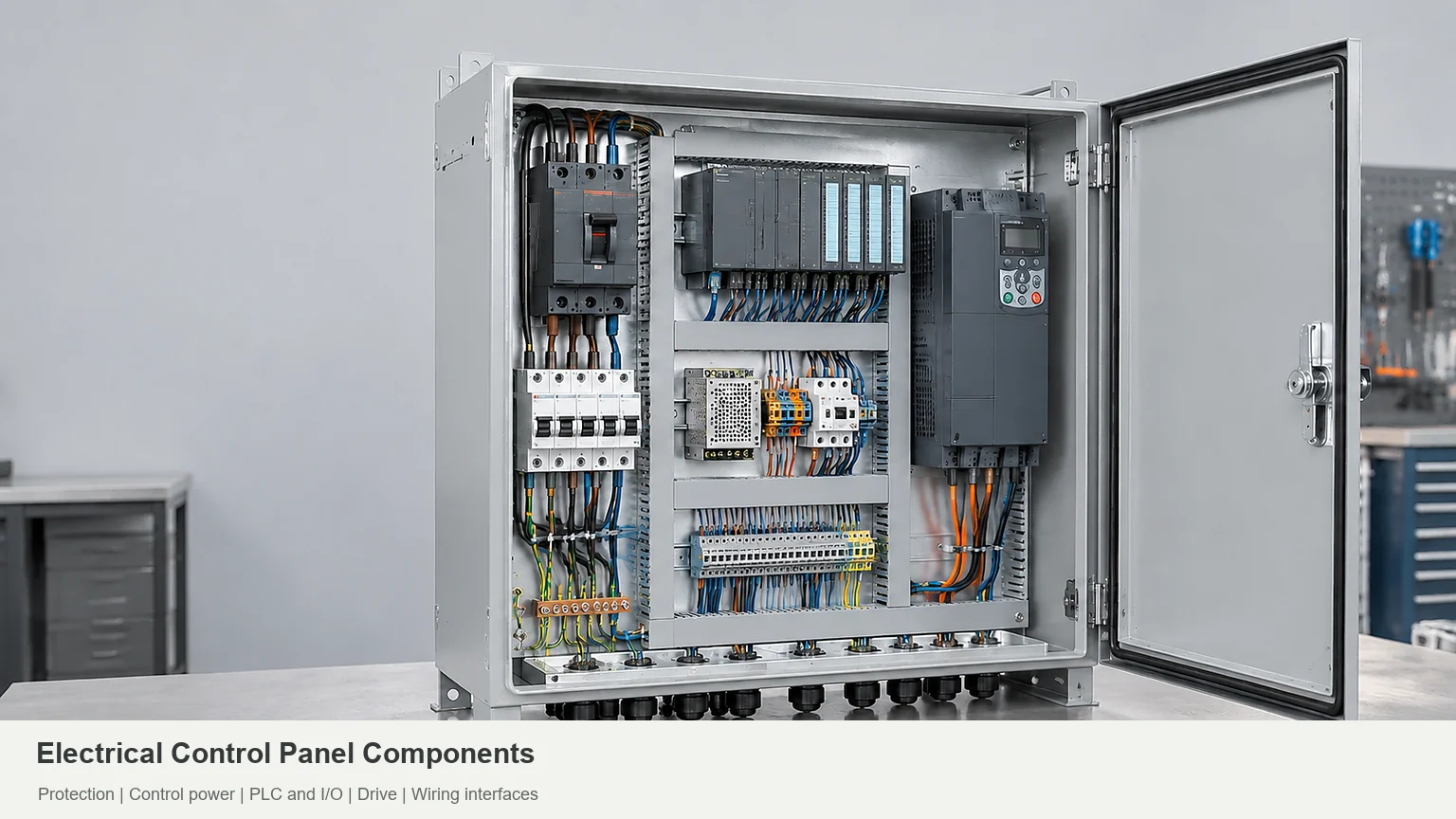

A control panel is easier to evaluate when power, control, wiring, and enclosure interfaces are visible together.
Electrical control panel components distribute power, protect circuits, control equipment, and connect operators to the process. A typical panel combines disconnects, circuit protection, contactors, control power, terminals, and an enclosure. PLCs, HMIs, and drives belong on the list when the application needs them UL Solutions panel guidance; Eaton’s UL 508A design guide; RealPars control panel overview.
If you’re checking electrical control panel parts against a BOM, don’t stop at the parts list. Check what each device needs around it: wires, plugs, airflow, mounting hardware, and room for a hand or tool. Fitting a component on the drawing isn’t the same as being able to connect or replace it Rockwell’s wiring and grounding guidelines; FN’s industrial automation enclosure guide.
Electrical Control Panel Components at a Glance
Use this list to read a bill of materials (BOM). For industrial control panel components, the useful question is not whether every panel has the same parts; it is whether each selected part has a defined job and a workable interface. This list covers common groups, not a requirement to buy all fifteen UL Solutions panel guidance; Eaton’s UL 508A design guide; RealPars control panel overview.
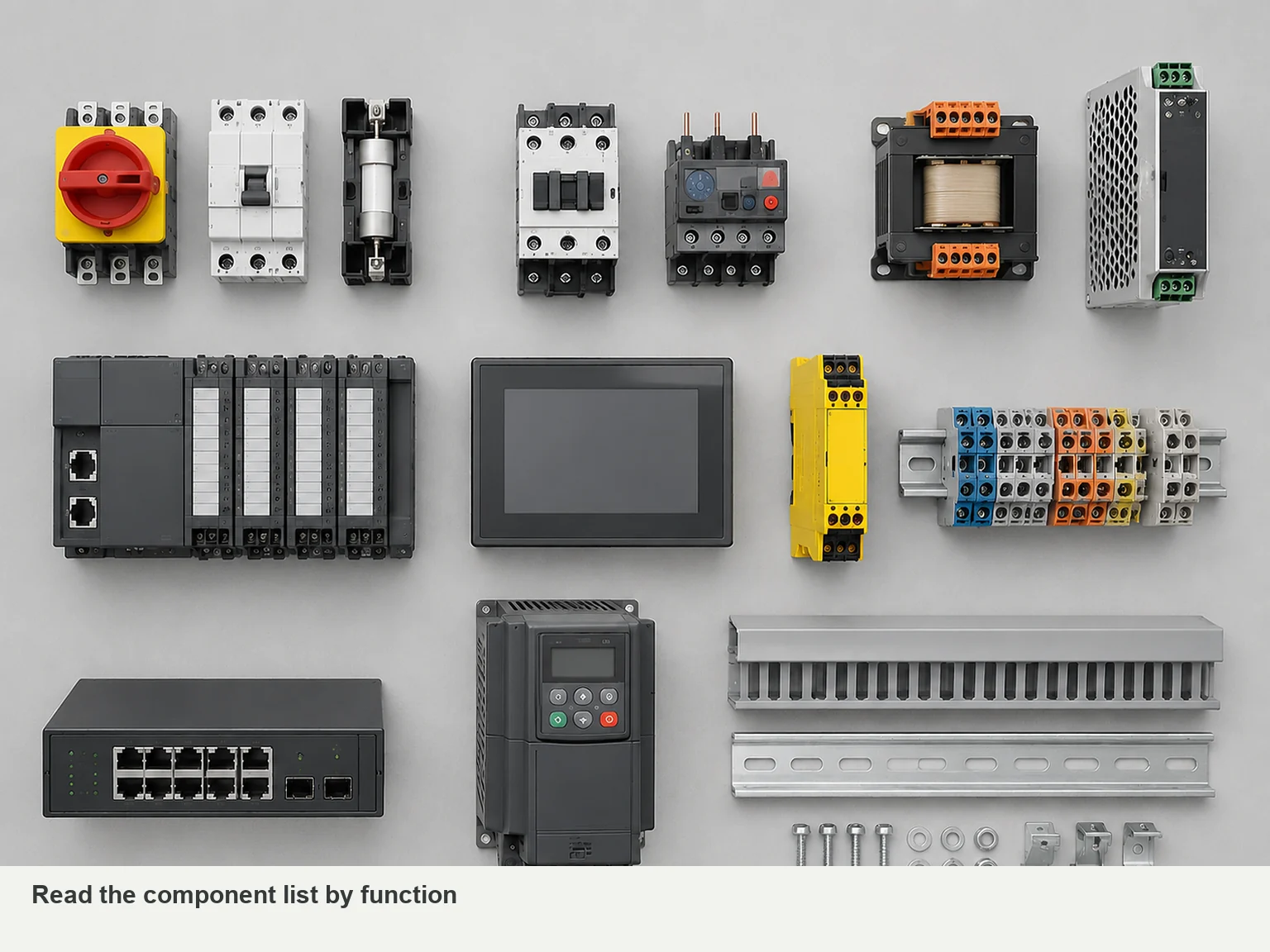
| Component | What it does | Check before ordering |
|---|---|---|
| Enclosure and mounting plate | House and support the assembly | Usable depth, mounting loads, environment, and drawing revision |
| Main disconnect | Disconnects the specified supply circuit | Electrical ratings, operating mechanism, and isolation scope |
| Circuit breakers or fuses | Provide the specified overcurrent protection | Circuit role, ratings, and downstream device requirements |
| Power distribution blocks | Split power into outgoing circuits | Wire sizes, connection capacity, and assembly suitability |
| Transformer or DC power supply | Provides the required control voltage | Input supply, output demand, and startup load |
| Contactors | Switch motors or other loads | Load duty, coil voltage, and switching frequency |
| Motor overload protection | Protects against specified motor overload conditions | Motor data, adjustment range, and other required protection |
| VFD or soft starter | Controls motor speed or starting behavior, respectively | Whether the process needs speed control or controlled starting |
| PLC and I/O modules | Run programmed logic and handle input/output signals | Signal types, channel count, communications, and software handover |
| HMI, buttons, and indicators | Accept operator commands and display status | Operator tasks, device models, cutouts, and rear clearance |
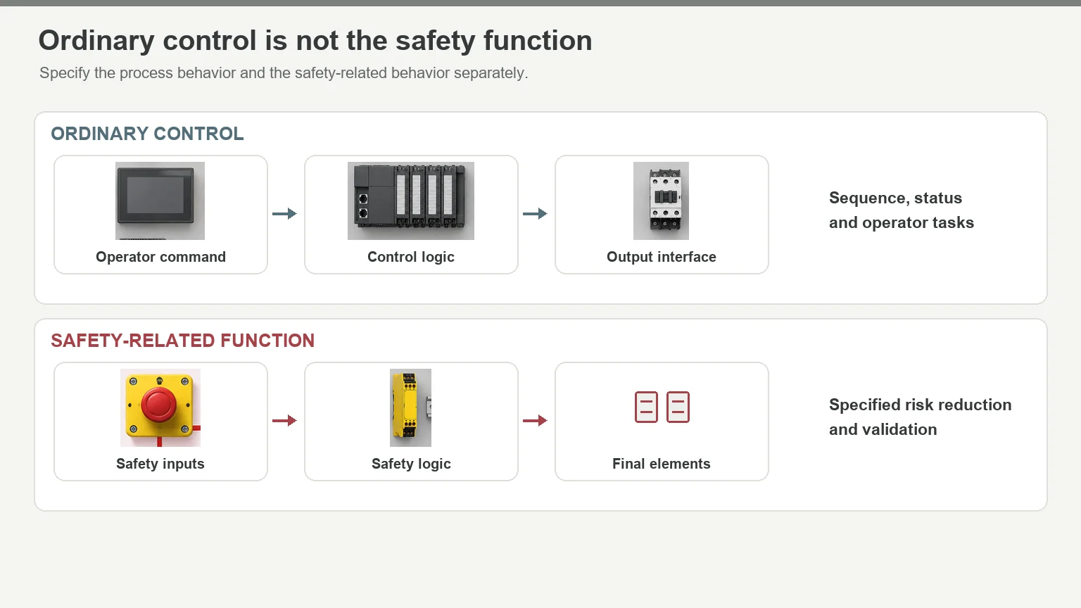
| Safety relay or safety controller | Performs specified safety-related logic | Risk assessment, required behavior, and validation responsibility |
| Terminal blocks and PE terminals | Connect field wiring and protective earth conductors | Wire sizes, connection method, labels, and tool access |
| Industrial network switches | Connect communicating automation devices | Ports, protocols, diagnostics, and configuration backup |
| DIN rails, wire ducts, and labels | Support devices and organize wiring | Fixing points, routing space, and access for maintenance |
| Fans, cooling units, heat exchangers, or heaters | Manage temperature or condensation | Heat load, ambient conditions, contamination, and service access |
A programmable logic controller (PLC) usually sits inside the cabinet. The human-machine interface (HMI) may sit on its door or at a separate operator station. Motors, sensors, and valves are commonly outside. Mark that boundary on the drawings so the quote separates panel equipment from field equipment RealPars control panel overview; FN’s industrial automation enclosure guide.
How the Components Work Together
Take a pump as a simple example. A level sensor sends a signal to a controller. The controller issues a run command, and a starter or drive operates the motor. The HMI, if fitted, gives the operator status information and controls Eaton’s UL 508A design guide; RealPars control panel overview.
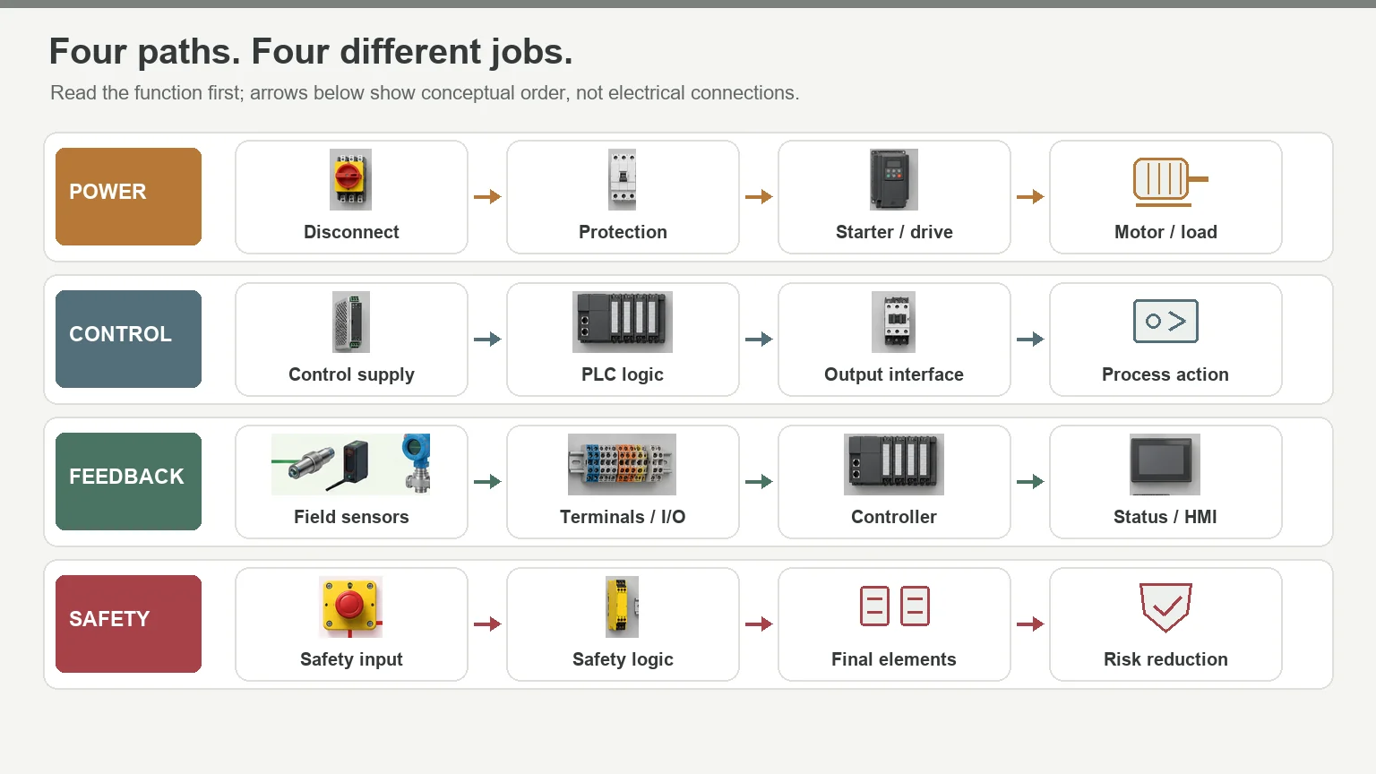
The sensor measures, the controller decides, and the starter or drive handles the motor. Circuit protection and safety-related controls have separate duties. Keep those duties separate in the specification, even when one product combines several functions UL Solutions panel guidance; Eaton’s UL 508A design guide; Rockwell’s safety documentation.
Seven Checks Before You Approve the Panel
1. Know what switches—and what protects
A contactor switches a load. It doesn’t automatically provide short-circuit protection. Motor overload protection serves a different purpose from branch-circuit short-circuit protection, too. A combined device may cover several duties, but its selection must establish which ones UL Solutions panel guidance; Eaton’s UL 508A design guide.
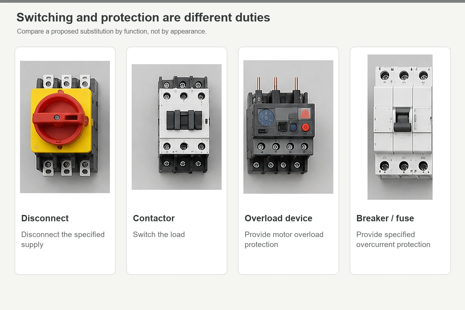
Have the designer identify switching, overload protection, and short-circuit protection on the schematic. That makes a proposed substitution easier to review: you’re comparing functions, not just matching current ratings. For the protection basics, see how a circuit breaker works.
2. Choose motor control for the job
Does the motor need to run at different speeds, or does it only need controlled starting? A variable-frequency drive (VFD) and a soft starter answer different questions. A contactor handles switching duties; a drive isn’t automatically the better choice Eaton’s UL 508A design guide.
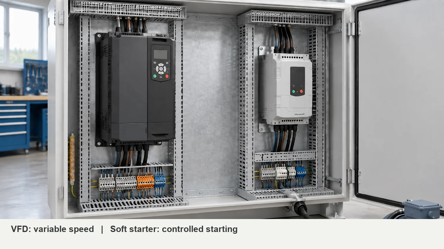
Define speed, starting frequency, load behavior, and stopping requirements before comparing models. Then get the selected device’s dimensions, weight, heat loss, and clearance requirements. Motor output power isn’t the heat load inside the cabinet FN’s industrial automation enclosure guide.
3. Size control power for startup, too
The transformer or DC supply must match the incoming supply and connected control equipment. Some panels need both devices; others don’t Eaton’s UL 508A design guide.
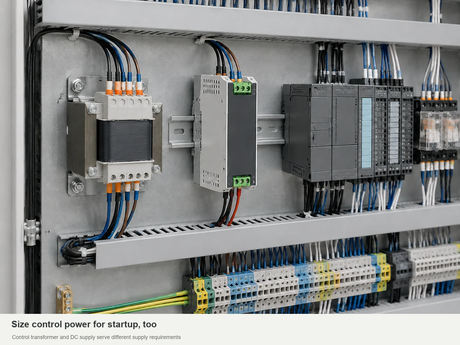
List the PLC, HMI, sensors, relays, and other control loads. Have the designer check steady demand and simultaneous startup demand. If backup power or redundancy matters to the process, put it in the specification now—not after the power supply has been ordered.
4. Define the behavior before choosing the PLC and HMI
The PLC runs the control program. The HMI displays information and accepts commands. They work together, but they aren’t interchangeable RealPars control panel overview.
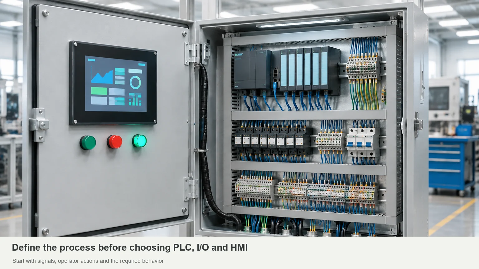
Start with an I/O list: digital inputs and outputs, analog signals, temperature signals, and networked devices. For the screen, list the operator’s actual tasks—starting a sequence, reading a measurement, changing a setting, or acknowledging an alarm. Those tasks should drive the interface choice.
Treat safety-related behavior separately. A safety-rated device alone doesn’t validate the whole function; the inputs, logic, outputs, and validation must work together. Assign that work to the responsible safety designer Rockwell’s safety documentation.
5. Leave room to connect and replace devices
A terminal strip needs more than space for its plastic housings. It needs room for incoming wires, labels, and connection tools. Drives and other serviceable devices also need a usable removal path Rockwell’s wiring and grounding guidelines; FN’s industrial automation enclosure guide.
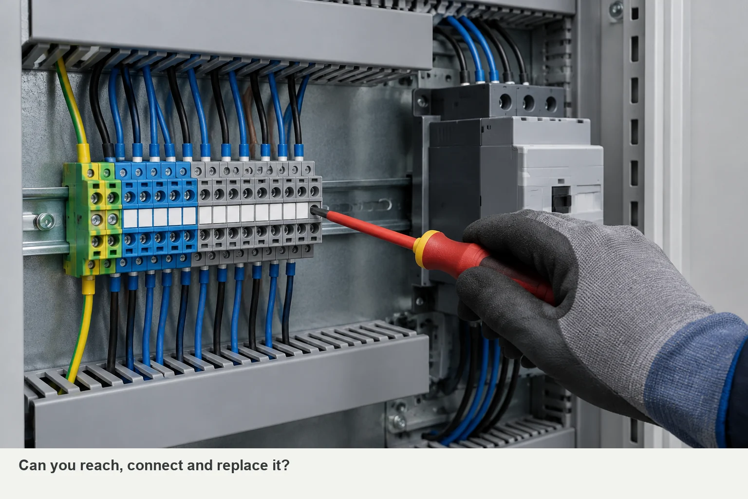
Review the terminal plan, cable entries, and component layout together. Can you reach a connection after the ducts are filled? Can you replace a device without removing the one beside it? These questions reveal space requirements that a bare mounting-plate layout can miss.
Keep noisy power wiring and sensitive signals arranged to the manufacturer’s guidance. Specify grounding and bonding connections rather than assuming that a DIN rail or painted metal surface supplies the intended connection Rockwell’s wiring and grounding guidelines.
6. Treat heat and moisture as separate problems
An operating drive may need heat removal; a cold cabinet may need condensation control. An enclosure heater addresses a different problem from a fan or cooling unit STEGO’s condensation guide.
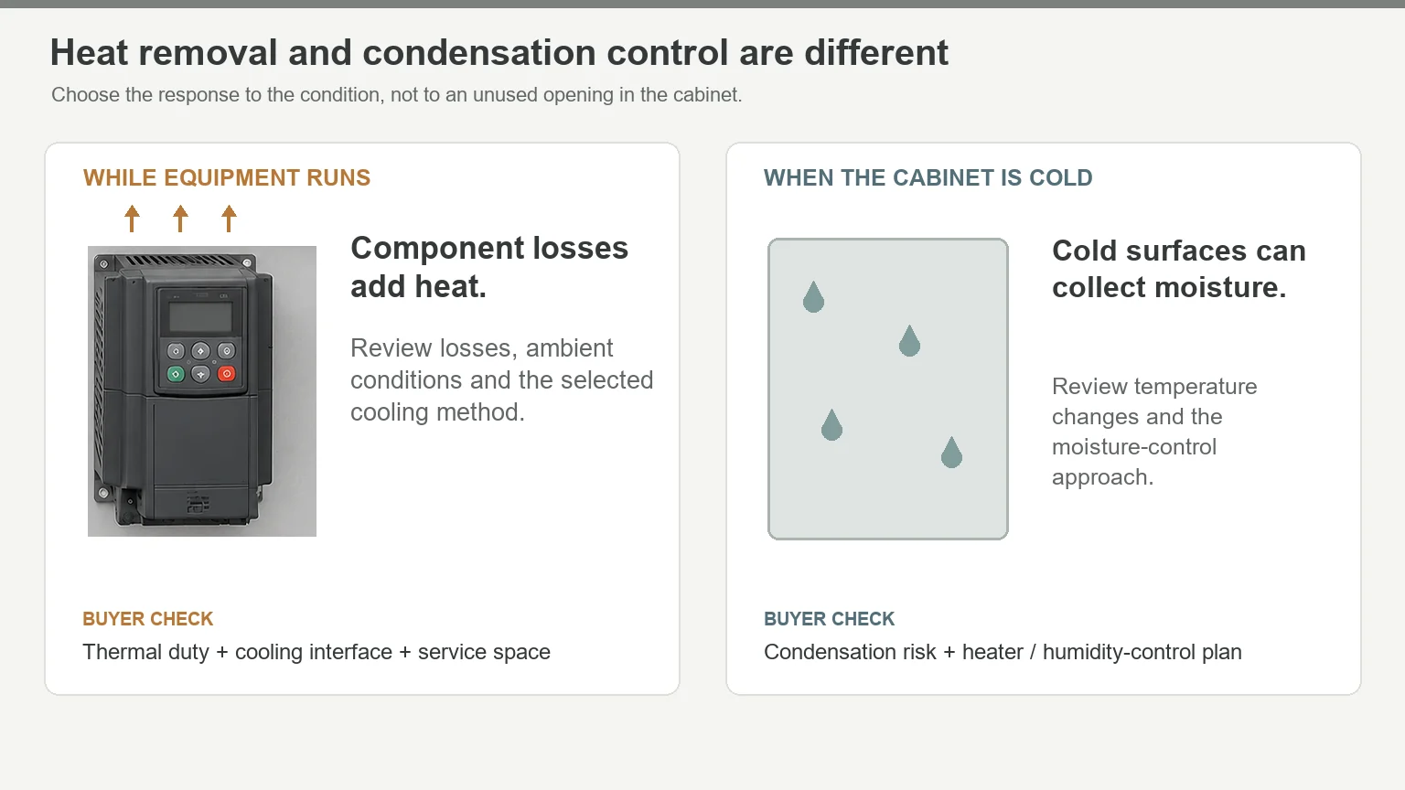
Base the thermal review on component losses, ambient temperatures, sun exposure, and permitted contamination. Reserve space for the selected equipment and its service access. Choosing a cooling unit because it fits a spare opening reverses the design process FN’s industrial automation enclosure guide.
7. Check the panel rating, not a collection of labels
For a project using short-circuit current rating (SCCR), request the completed panel’s rating and supporting method. The interrupting rating printed on one breaker is not the assembly’s SCCR. The panel rating must be reviewed against the available fault current and the selected component arrangement Rockwell’s SCCR guidance.
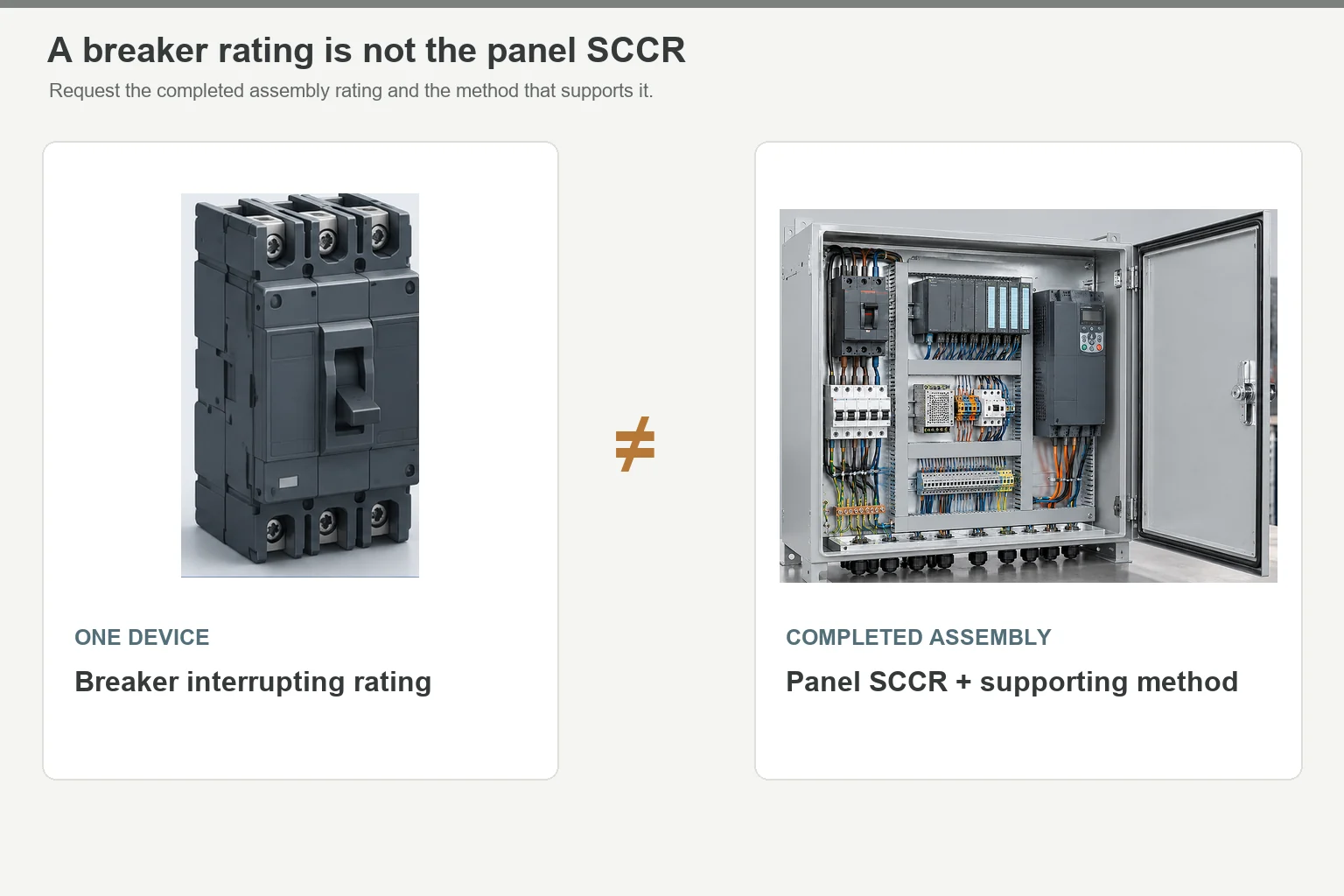
The same distinction applies to certification: approved components don’t automatically produce an approved panel. UL’s panel program also addresses wiring, protection, environmental ratings, and markings UL Solutions panel guidance.
Keep the enclosure requirement specific. Openings, gaskets, hardware, and assembly affect the finished configuration; an IP or NEMA target doesn’t replace that review FN’s industrial automation enclosure guide.
Three Applications, Three Different Component Lists
Brewery: individual temperature loops
Axis Controls built a panel for Sambrooks Brewery with temperature controllers operating cooling-water solenoid valves for nine fermentation tanks. The controllers and operator controls sat on the door of a stainless-steel enclosure Axis Controls’ brewery case study.
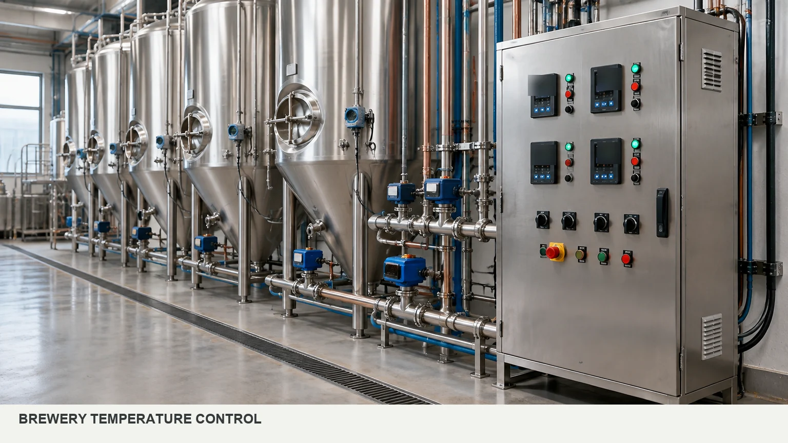
For a job like this, list the control loops and operator adjustments first. Then decide how much control hardware the process needs—and how much door space those controls will occupy.
Pressure testing: sequence and measurement
AutomationDirect describes a pressure-test project involving Stephens Machine and Par Electric & Engineering. The panel combined a Productivity2000 PLC, C-more HMI, motor starter, control transformer, circuit protection, and control and safety relays. It sequenced valves and evaluated pressure behavior AutomationDirect’s pressure-test case study.
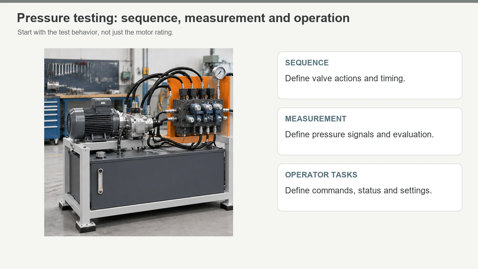
A motor rating alone won’t specify that panel. The test sequence, measurement signals, and operator screens belong in the purchasing brief.
Solar monitoring: network diagnostics
Gantner Instruments uses WAGO managed Ethernet switches in photovoltaic monitoring and control cabinets. WAGO’s published application describes their role in network diagnostics and monitoring WAGO’s Gantner application.
Put the switch configuration, port labels, and replacement procedure in the handover package—not just the switch on the BOM.
Freeze the Interfaces Before Releasing the Enclosure
An HMI’s screen size isn’t a cutout drawing. You need its exact model, mounting geometry, rear depth, and connector clearance. The front can fit while the space behind it is wrong FN’s industrial automation enclosure guide; FN’s enclosure vs. control panel guide.
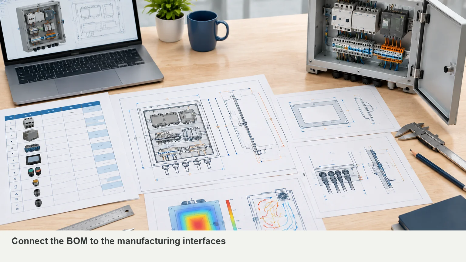
The same principle applies to drives, cable entries, and cooling equipment. Use the matrix below to turn component choices into drawing requirements. FN’s industrial automation enclosure guidance covers the inputs for these interfaces FN’s industrial automation enclosure guide.
| Selected item | Information to confirm | What belongs on the drawing |
|---|---|---|
| HMI | Exact model and mounting drawing | Cutout, corner geometry, fixing points, rear depth, and plug access |
| Door-operated disconnect | Exact operating mechanism | Handle position, shaft/interface geometry, and internal clearance |
| Drive or soft starter | Dimensions, weight, losses, and required spacing | Supports, airflow clearances, and cable approach |
| Terminal blocks and ducts | Terminal plan, wire sizes, and routing | Connection access, duct capacity, and field-wiring space |
| Cable glands or entry plates | Cable count, diameters, direction, and entry devices | Hole pattern, sealing interfaces, and bending space |
| Cooling equipment | Selected model and installation requirements | Opening, mounting, clearances, and service access |
| Future equipment | Defined devices or a reserved zone | Space that remains free after wiring and cooling are included |
Change the HMI or drive after approval? Review the drawing before fabrication. Matching the old device’s electrical duty doesn’t prove that the new one fits the same opening or mounting pattern FN’s enclosure vs. control panel guide.
Keep quotation drawings and fabrication drawings clearly marked. A provisional layout can support a discussion; the factory needs the approved revision to cut, drill, and assemble. The enclosure vs control panel guide explains that handoff FN’s enclosure vs. control panel guide.
What to Send with Your Enclosure RFQ
Send one matching set of files—not a current BOM with an older door drawing:
- BOM: manufacturer, exact part number, quantity, and data sheets.
- Layout: overall size, mounting plate, door equipment, and reserved space.
- Interfaces: cutouts, mounting patterns, cable entry, and installation details.
- Environment: temperatures, dust, moisture, washdown, corrosion, and location.
- Thermal requirements: component losses and the system designer’s cooling or heating plan.
- Order details: quantity, destination, drawing status, supply scope, and acceptance documents FN’s industrial automation enclosure guide; FN’s custom enclosure guide; FN’s enclosure vs. control panel guide.
Keep responsibilities visible in the quote. FN can build the enclosure body and agreed mechanical interfaces. Assign electrical design, wiring, software, thermal design, safety validation, and final system approval to named project owners FN’s industrial automation enclosure guide; FN’s enclosure vs. control panel guide.
Have a preliminary BOM or layout? Send it to FN for a mechanical scope review before the enclosure drawing is released. Include any fixed cutouts, cable-entry limits, installation space, and unresolved component selections.
Frequently Asked Questions
The main groups are power entry, protection, load switching, control power, control logic, operator interfaces, terminals, and the enclosure. Add drives, network equipment, or climate control when the application calls for them UL Solutions panel guidance; Eaton’s UL 508A design guide; RealPars control panel overview.
No. The control task determines the hardware. The brewery example uses dedicated temperature controllers; the pressure-test example combines a PLC and HMI for sequencing and operator interaction. Start with the process, not a standard shopping list Axis Controls’ brewery case study; AutomationDirect’s pressure-test case study.
No. Motor overload protection and circuit overcurrent protection have different roles. Some devices combine functions, so check the selected device and circuit arrangement rather than relying on its name Eaton’s UL 508A design guide.
No. The assembly also needs the appropriate component use, wiring, protection, ratings, and markings. Where your project requires panel certification, request evidence for the completed panel UL Solutions panel guidance.
Yes. Send the preliminary BOM, sketch, or size envelope and mark what’s unresolved. Cutouts, mounting positions, cable entries, and clearances need an approved basis before fabrication—not before the first conversation FN’s custom enclosure guide; FN’s enclosure vs. control panel guide.
Start with the BOM or Sketch You Have
You don’t need to guess every missing dimension before contacting FN. Send the files you have for your custom electrical enclosure. We’ll identify the missing mechanical inputs and the next step toward an approved drawing and quotation FN’s custom enclosure guide; FN’s enclosure vs. control panel guide.
Send your BOM or sketch to FN, along with the environment, quantity, and any fixed installation limits.
Sources
- UL Solutions — Industrial Control Panels and the Panel Shop Program
- Eaton — Control Panel Design Guide (UL 508A)
- RealPars — What Is an Electrical Control Panel?
- Rockwell Automation — Industrial Automation Wiring and Grounding Guidelines
- Rockwell Automation — Short-circuit Current Ratings
- STEGO — Condensation in Your Control Cabinet
- Axis Controls — Sambrooks Brewery Case Study
- AutomationDirect — Automation Expands Machine Shop’s Success
- WAGO — Gantner Instruments Customer Application
- FN Enclosure — Industrial Automation Enclosures
- FN Enclosure — Custom Electrical Enclosures
- FN Enclosure — Electrical Enclosure vs Control Panel
- Rockwell Automation — Safety Solutions Technical Documentation