
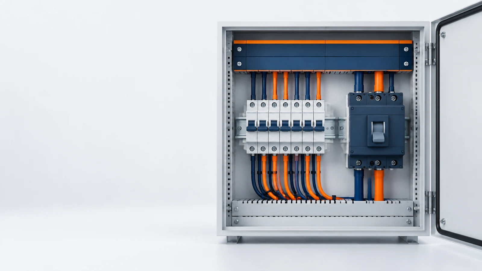

Short answer: A circuit breaker detects a fault, releases a trip mechanism, pulls its contacts apart, controls the arc between them, and interrupts the current. The important detail is that different breakers detect different problems. An MCB, MCCB, RCD, RCBO, GFCI, AFCI, ACB, and VCB are not interchangeable labels for the same device.
If you only remember one selection rule, make it this:
Do not choose a circuit breaker by amperage alone. Check the fault type, system voltage, available short-circuit current, interrupting rating, trip behavior, coordination, and installation conditions.
What Is a Circuit Breaker?
A circuit breaker is a switch with a protection function. It can open and close a circuit manually, but it can also open the circuit automatically when it detects an electrical condition outside its design limits.
That makes it different from an ordinary switch. A switch waits for a person or control signal. A circuit breaker watches the circuit through a thermal, magnetic, electronic, residual-current, or arc-fault sensing method. When the relevant trip condition is reached, the breaker releases its operating mechanism and opens the current path.
The protection depends on the device. A standard thermal-magnetic breaker is typically used for overcurrent protection. A residual-current device looks for current imbalance or leakage. An arc-fault device looks for electrical patterns associated with arcing. One device should not be described as providing all of these functions unless its product documentation and listing say so. (Schneider Electric) (UL Solutions)
How Does a Circuit Breaker Work?
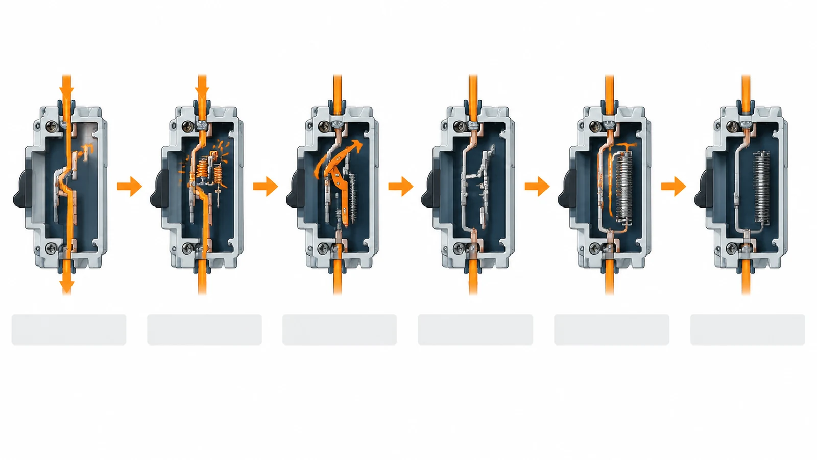
The process is easier to understand if you follow the current through the device:
- A fault or abnormal condition appears.
- A sensing element detects it.
- The sensing element releases the trip mechanism.
- The operating mechanism separates the contacts.
- The breaker controls the arc created by the opening contacts.
- The circuit stays open until it is safely reset, reclosed, or serviced.
The sequence is general. The sensing method, speed, arc-control structure, interrupting medium, and reset procedure change with the breaker family and voltage class.
1. The breaker detects an abnormal condition
A breaker must tell the difference between normal operating current and a condition that could damage the circuit.
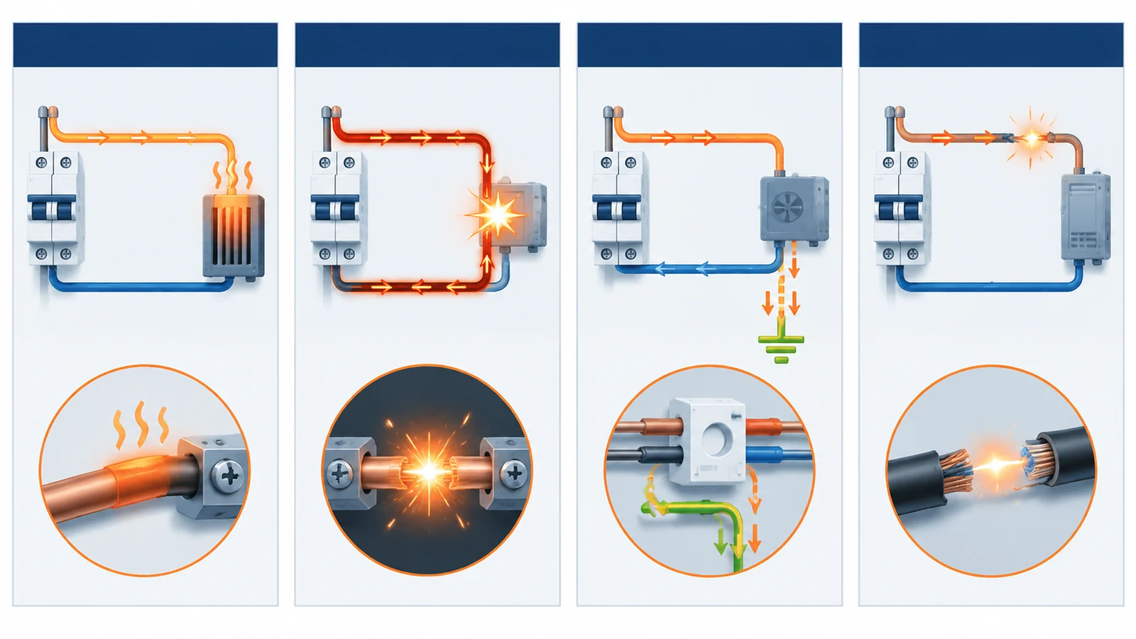
The most common conditions are:
- Overload: The circuit carries too much current for too long. Heat builds up in the conductors and connected equipment.
- Short circuit: A low-impedance fault creates a very high current. The breaker must respond quickly.
- Ground fault or residual current: Some current leaves its intended path or the current returning through the monitored conductors is no longer balanced.
- Arc fault: An unintended arc creates a signal pattern that a suitable arc-fault device is designed to recognize.
- Inrush current: A motor, transformer, power supply, or capacitor may draw a temporary surge that should not be mistaken for a sustained fault.
This distinction matters when you specify the device. A standard overcurrent breaker is not automatically a ground-fault or arc-fault protective device.
2. The trip unit releases the mechanism
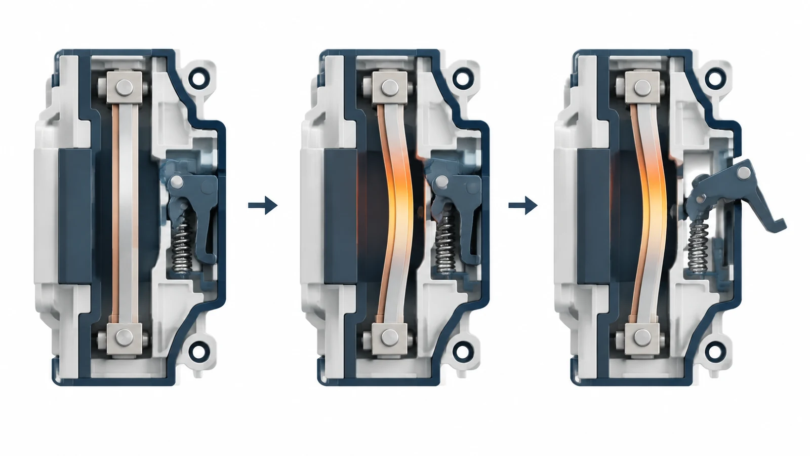
When the sensing element reaches its trip condition, it releases a latch inside the breaker. The latch releases stored mechanical energy, allowing the operating mechanism to open the contacts. The handle may move to a tripped position, but the handle itself is not what detects the fault.
The most common trip methods are:
Thermal trip: A temperature-sensitive element responds to sustained overcurrent. In a thermal-magnetic breaker, a bimetal element heats, bends, and releases the mechanism.
Magnetic trip: An electromagnetic element responds to a high current, such as a short circuit, and trips much faster than a thermal element.
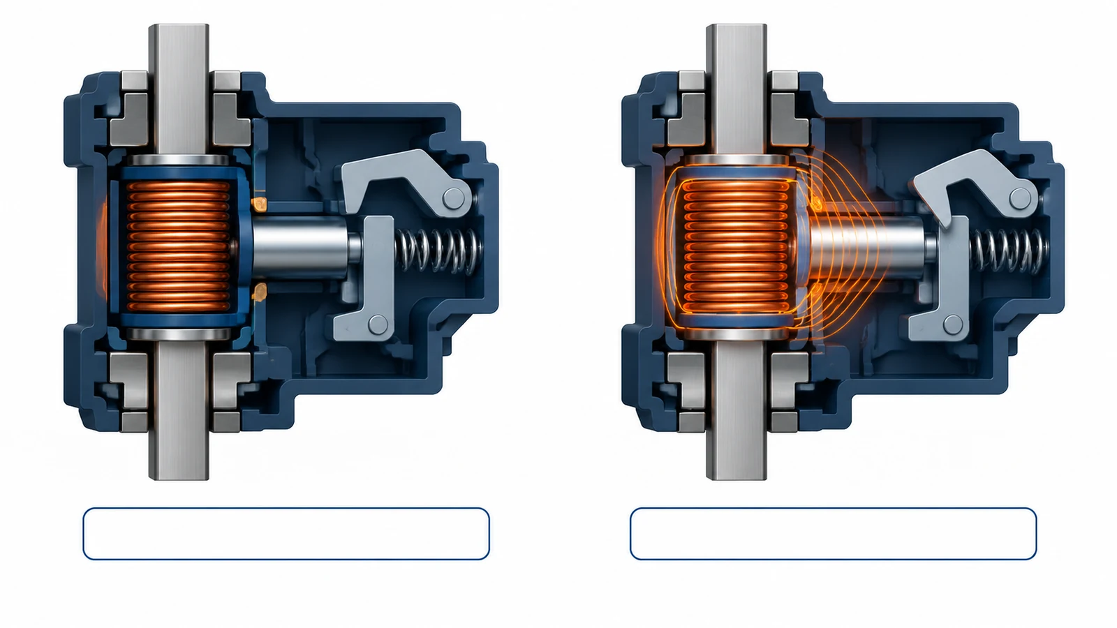
Electronic trip: Sensors and electronic logic evaluate current against configured trip settings. This is common in larger MCCBs and ACBs.
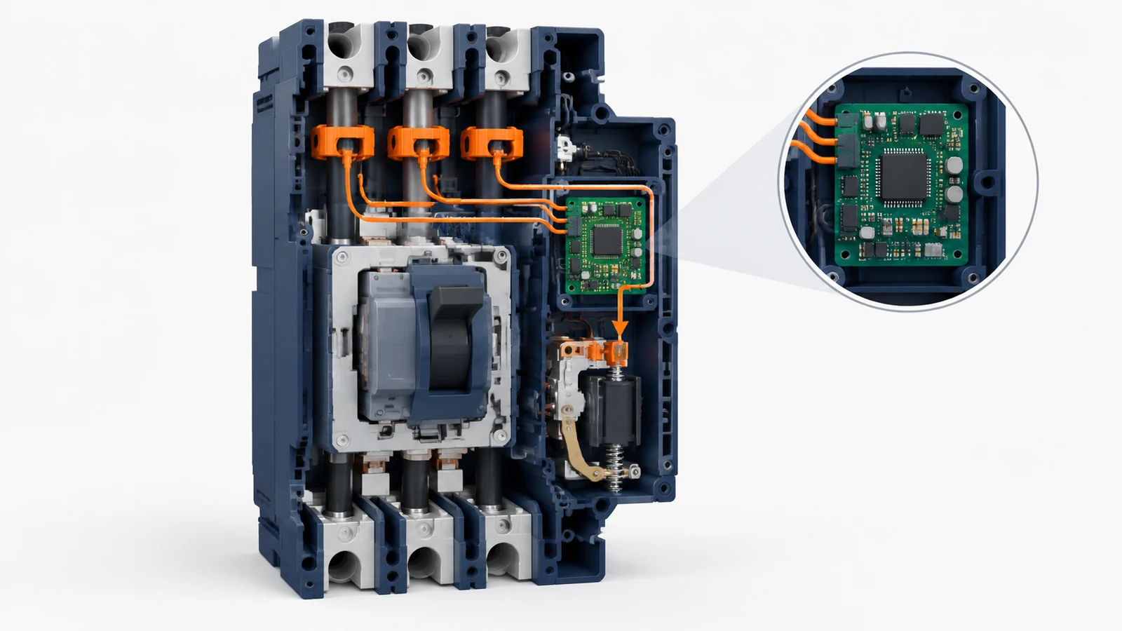
- Residual-current trip: A sensing circuit detects an imbalance between current paths and initiates a trip when the device’s threshold is exceeded.
- Arc-fault detection: An AFCI analyzes electrical signals for characteristics associated with an unintended arc. Listed devices also have specific markings and test functions. (UL Solutions)
Many breakers combine two or more methods. Schneider Electric describes a traditional molded-case breaker as combining a temperature-sensitive device with a current-sensitive electromagnetic device.
3. The contacts separate
Once the mechanism trips, the moving contact pulls away from the fixed contact. Current no longer has a continuous metal path through the breaker.
But opening the contacts does not instantly make the circuit electrically quiet. If current is flowing, the voltage across the opening gap can sustain an arc. The arc is a hot, conductive path that can continue carrying current between the contacts.
That is the part many basic explanations skip.
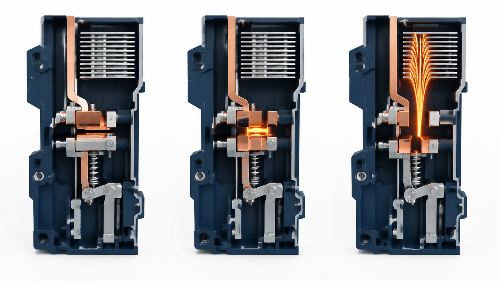
4. The breaker controls and extinguishes the arc
A circuit breaker must manage the arc without allowing it to restrike across the opening gap. Depending on the design, it may use:
- An arc chute or arc splitter;
- Magnetic forces to move and stretch the arc;
- Cooling and deionization of the arc path;
- Air, vacuum, oil, gas, or another interrupting medium;
- Rapid contact separation;
- Current-limiting behavior that reduces let-through energy.
The interrupting medium and arc-control method are major reasons why a low-voltage MCB, an industrial MCCB, an ACB, and a medium-voltage VCB should not be treated as scaled versions of one another.
5. The circuit remains open
After the breaker interrupts the fault, it remains open until a person, control system, or maintenance procedure resets or recloses it.
A breaker that trips repeatedly is giving you information. It may be responding to an overload, short circuit, ground fault, arc fault, damaged equipment, loose connection, incorrect sizing, or a problem inside the breaker. Repeatedly resetting it without finding the cause is not a repair strategy.
What Are the Main Parts of a Circuit Breaker?
The construction changes by breaker family, but most low-voltage breakers include some version of these parts:
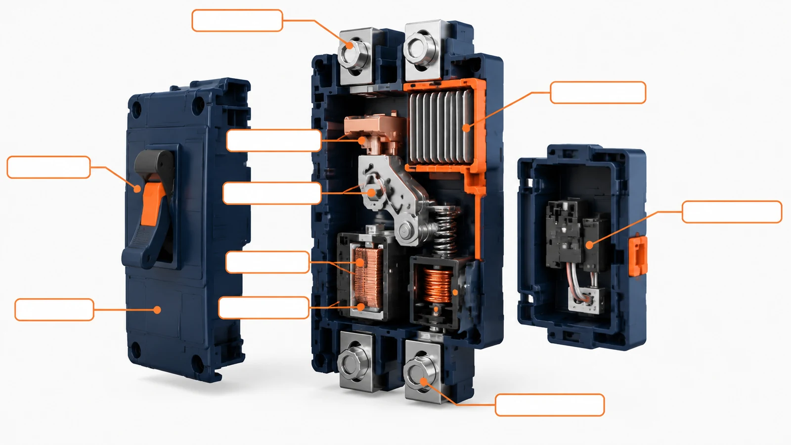
| Part | What it does |
|---|---|
| Housing or molded case | Insulates and protects the internal mechanism. |
| Line and load terminals | Connect the breaker to the supply and protected circuit. |
| Fixed and moving contacts | Carry current when closed and separate to interrupt it. |
| Operating handle or actuator | Allows manual operation and indicates the device state. |
| Trip unit | Detects a defined fault condition and starts the trip action. |
| Thermal element | Responds to sustained heating from overcurrent, where fitted. |
| Magnetic element | Responds to high fault current, where fitted. |
| Electronic sensors and logic | Measure current and apply electronic trip settings. |
| Operating mechanism | Stores and releases the energy needed to open the contacts. |
| Arc-control structure | Controls the arc during interruption. |
| Auxiliary or alarm contacts | Provide status or trip signals in some designs. |
A useful circuit breaker diagram should show two paths at once:
- the current path through the terminals and contacts; and
- the protection path from sensing element to trip mechanism.
That simple separation makes the device easier to understand than a picture covered with unexplained labels.
What Does a Circuit Breaker Protect Against?
The answer depends on the breaker’s protection function. Use the table below as a starting point, not as a substitute for the product documentation.
| Fault or condition | Protection function commonly used | What to check |
|---|---|---|
| Sustained overload | Thermal or electronic overcurrent protection | Trip curve, load current, conductor capacity, and ambient conditions |
| Short circuit | Magnetic, instantaneous, or electronic overcurrent protection | Available fault current and interrupting rating |
| Ground fault or leakage | Residual-current or ground-fault protection | Device function, threshold, conductor arrangement, and installation rules |
| Arc fault | Arc-fault circuit-interrupter function | Product marking, test function, wiring method, and application |
| Motor or transformer inrush | Correct trip characteristic and coordination | Starting current, duration, and downstream equipment |
| Manual isolation | Switching or isolation function | Device rating, isolation requirements, and safe operating procedure |
The key point is simple: a breaker can only protect against the conditions its design is intended to detect. UL Solutions separates general molded-case breaker markings from special markings for devices that also provide ground-fault or combination arc-fault functions.
Types of Circuit Breakers and Their Functions
Circuit breaker terms become much clearer when you separate two questions:
- What is the breaker built for? Construction, voltage class, current range, and interrupting medium.
- What does it protect against? Overcurrent, residual current, ground fault, arc fault, or another defined condition.
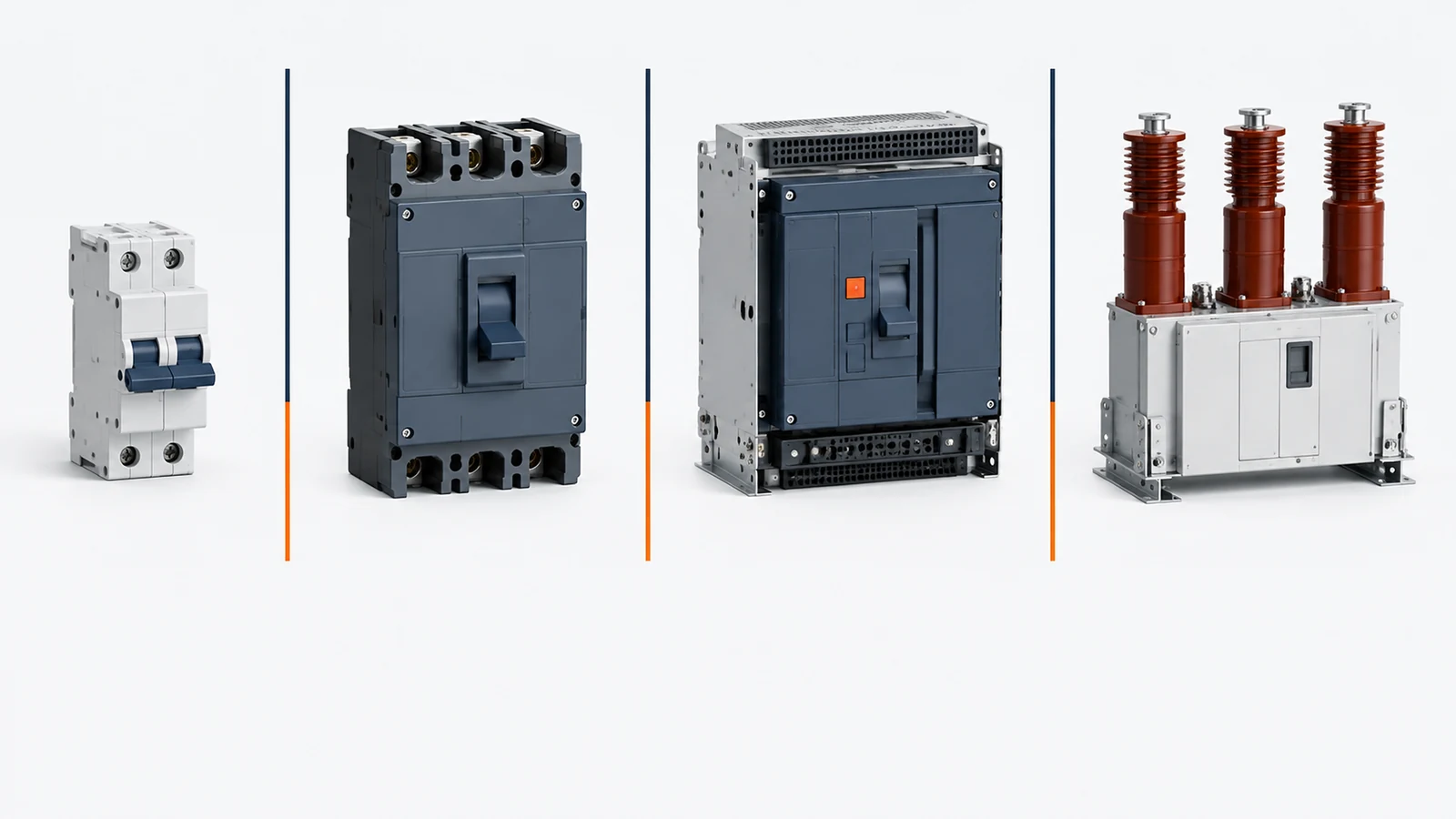
MCB: Miniature Circuit Breaker
An MCB is a compact breaker commonly used for branch-circuit overcurrent protection in residential, commercial, and light-industrial systems.
Typical selection points include:
- Rated current;
- System voltage;
- Number of poles;
- Trip characteristic;
- Interrupting rating;
- Terminal and mounting compatibility.
Many MCB ranges use B, C, or D trip-characteristic letters. Do not select a curve from the letter alone. Confirm the manufacturer’s time-current data and make sure the selected curve suits the connected load.
MCCB: Molded Case Circuit Breaker
An MCCB is a larger molded-case breaker used for feeders, equipment protection, and industrial distribution. It may use a thermal-magnetic trip unit or an electronic trip unit, and some models provide adjustable settings.
An MCCB is not simply an MCB with a bigger amp number. It can bring different requirements for interrupting rating, trip settings, terminals, accessories, coordination, enclosure heat, and available short-circuit current. UL Solutions’ guide covers molded-case breaker ratings, terminations, adjustable trip units, and special markings.
ACB: Air Circuit Breaker
An ACB uses air as its interrupting medium and is commonly associated with larger low-voltage distribution equipment such as switchboards, main breakers, and feeder sections. In a project built around a power distribution enclosure, the breaker dimensions, door access, busbar layout, and service clearances must be checked together.
ACB selection is usually a system decision. You may need to review:
- Main or feeder load;
- Available fault current;
- Electronic trip settings;
- Coordination and selectivity;
- Draw-out or fixed installation;
- Maintenance access;
- Accessories, communication, and remote operation.
VCB: Vacuum Circuit Breaker
A VCB interrupts current in a vacuum interrupter and is commonly used in medium-voltage distribution and industrial systems.
The important design questions are different from those for a small branch breaker. Review system voltage, insulation coordination, switching duty, fault level, protection scheme, and maintenance requirements. Do not treat a VCB as a direct substitute for an MCB or MCCB.
SF6 and other medium- or high-voltage breakers
Some medium- and high-voltage breakers use gas or another specialized interrupting medium. Their design and maintenance can involve insulation, interrupting duty, environmental conditions, gas management, protection coordination, and project-specific requirements.
A general article can introduce these families, but detailed selection belongs in a dedicated medium-voltage or high-voltage guide.
RCD, RCCB, and RCBO
These terms are associated with residual-current protection, although terminology and product definitions vary by market and product standard.
- RCD: A broad term commonly used for residual-current protection devices.
- RCCB: A residual-current circuit breaker that generally does not provide the complete overcurrent function of an RCBO.
- RCBO: Combines residual-current protection with overcurrent protection in one device.
Confirm the exact function, system arrangement, product listing, and installation instructions before selecting one of these devices.
GFCI and AFCI
In North American terminology:
- GFCI refers to ground-fault circuit-interrupter protection.
- AFCI refers to arc-fault circuit-interrupter protection.
Both devices can open a circuit, but they do not perform the same job as a standard thermal-magnetic breaker. Their markings, test functions, wiring methods, and installation instructions matter. UL Solutions documents specific identification and test-related requirements for listed ground-fault and arc-fault devices.
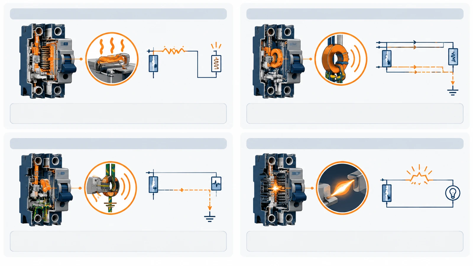
DC circuit breakers
Do not assume an AC breaker is suitable for DC service. DC interruption depends on the voltage, current, polarity, fault behavior, arc characteristics, switching duty, and the manufacturer’s DC ratings.
This matters in photovoltaic systems, batteries, energy-storage systems, and DC distribution. For renewable-energy equipment, review the breaker and the solar enclosure as one installation. Battery and energy-storage projects may need a different energy storage enclosure arrangement. A similar-looking current rating is not enough. Confirm the breaker’s actual DC application and interrupting ratings.
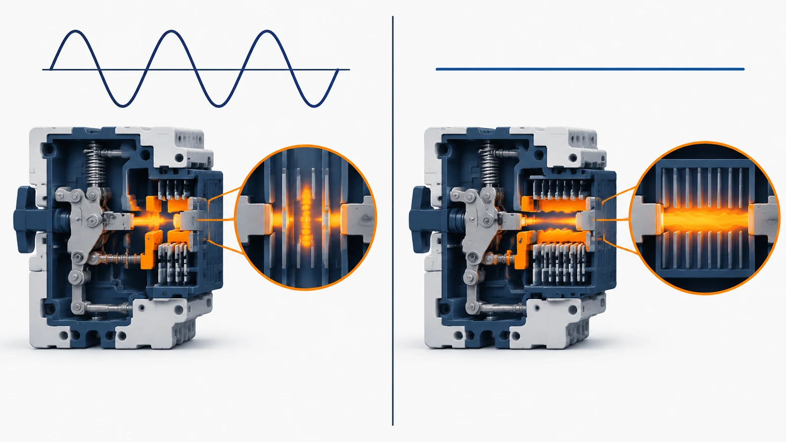
Why Do Circuit Breakers Trip?
A tripped breaker is not automatically a failed breaker. It is a protective response, and the timing of the trip can provide a useful clue.
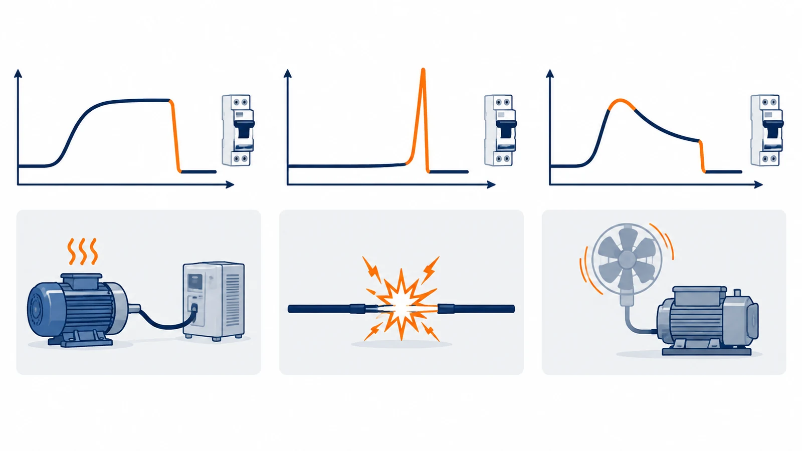
- Trips after the circuit runs for a while: Suspect sustained overload, heat buildup, poor ventilation, or a thermal condition.
- Trips immediately when a load is connected: Suspect a short circuit, ground fault, or severe inrush problem.
- Trips when a motor or transformer starts: Check starting current and the trip characteristic.
- Trips randomly or repeatedly: Check loose connections, damaged equipment, leakage, moisture, nuisance-trip conditions, or a breaker/accessory problem.
- A GFCI or RCD trips: Investigate current imbalance or leakage instead of replacing it with a standard breaker.
- An AFCI trips: Investigate the connected equipment, wiring, and arc-fault conditions using the product instructions and qualified testing.
Do not bypass the breaker. Do not replace it with a larger rating simply to stop the trips. The conductors, terminals, enclosure, and upstream/downstream protection must be reviewed together.
How Do You Select the Right Circuit Breaker?
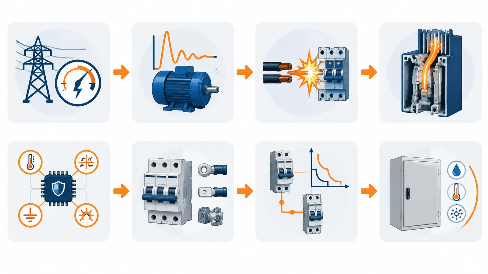
Use this order. It prevents the most common mistake: choosing an amp rating first and asking the other questions later.
1. Identify the system
Confirm AC or DC, system voltage, phase arrangement, frequency where relevant, installation location, and load type.
2. Confirm the normal load and inrush
Record the continuous operating current. Then check whether motors, transformers, capacitors, power supplies, or other equipment create a temporary inrush current.
3. Verify the available fault current
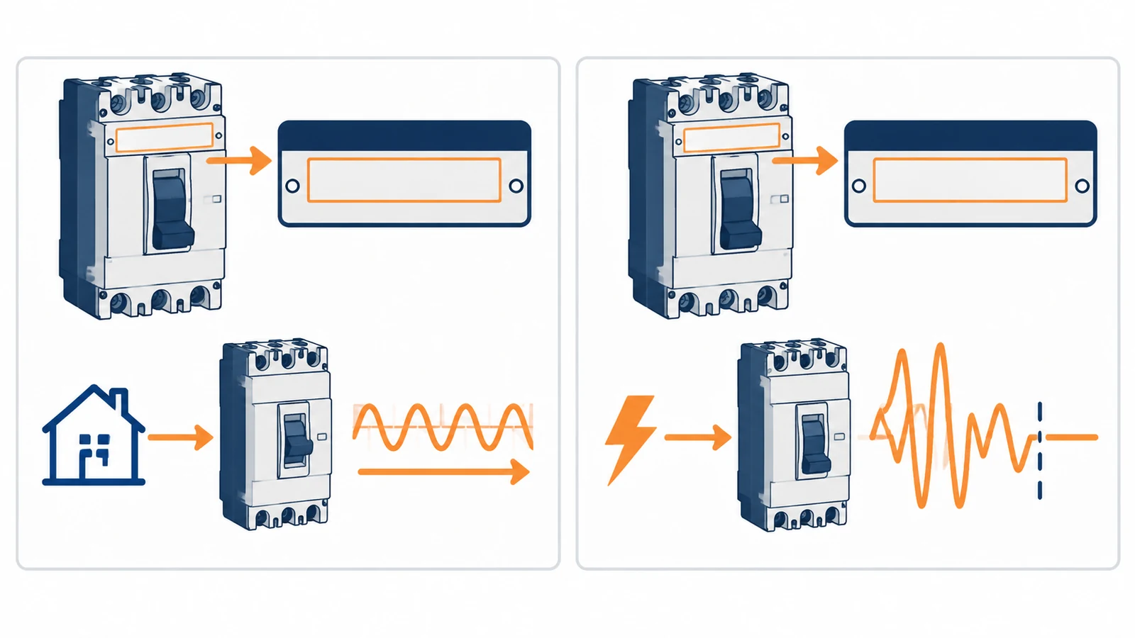
Normal load current tells you how the circuit operates. Available fault current tells you what the breaker may need to interrupt during a fault. They are not the same number.
4. Check the interrupting or breaking rating
A breaker’s normal rated current describes its current-carrying application. Its interrupting rating describes the fault current it is rated to interrupt under specified conditions.
This distinction belongs in every serious selection guide. UL Solutions notes that the overall combination may be limited by the lower short-circuit or interrupting rating marked on the end-use equipment in which the breaker is installed.
5. Choose the protection function
Decide whether the circuit needs:
- Overcurrent protection;
- Residual-current or ground-fault protection;
- Arc-fault protection;
- Shunt trip;
- Undervoltage release;
- Motor protection;
- Alarm or auxiliary contacts;
- Remote operation or communication.
6. Confirm poles, terminals, mounting, and accessories
Check the number of poles, neutral requirements, conductor range, terminal type, busbar compatibility, mounting arrangement, clearances, accessories, door access, and service space.
7. Review coordination and selectivity
The goal is not merely to make a breaker trip. In a coordinated system, the protective device nearest to the fault may be intended to operate first, allowing other circuits to remain energized.
Use manufacturer coordination data and the project protection study. Do not infer selectivity from a product name or a generic table.
8. Check the enclosure and environment
Temperature, altitude, enclosure heating, humidity, dust, vibration, corrosion, outdoor exposure, cable routing, and working space can change the final selection. OSHA’s electrical-safety resources emphasize the need to address electrical hazards through appropriate safety practices and controls.
Circuit Breaker vs. Fuse
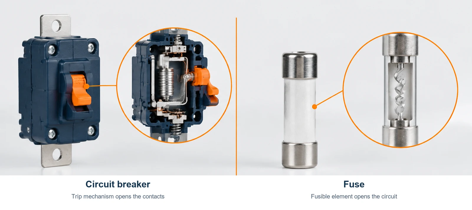
Both devices protect against excessive current, but they do it differently.
| Consideration | Circuit breaker | Fuse |
|---|---|---|
| After operation | Often resettable after the fault is cleared | Normally replaced |
| Interrupting action | Opens contacts through a trip mechanism | Melts a fusible element |
| Status | May provide handle, flag, auxiliary, or alarm indication | Depends on the fuse and holder |
| Adjustment | Some breakers offer adjustable trip settings | Selected by fuse type and rating |
| Maintenance | May need testing, inspection, or replacement | Requires replacement and holder inspection |
| Selection | Must consider trip behavior, coordination, and interrupting rating | Must consider fuse class, rating, interrupting capability, and coordination |
Neither is automatically the better choice. The decision depends on fault level, operating duty, maintenance strategy, space, coordination, replacement requirements, and project standards.
Circuit Breakers Inside Electrical Enclosures
Once a breaker is installed in a panel or enclosure, the surrounding system becomes part of the design. A correctly rated breaker can still create problems if the enclosure leaves no room for heat dissipation, cable bending, terminal access, or maintenance.
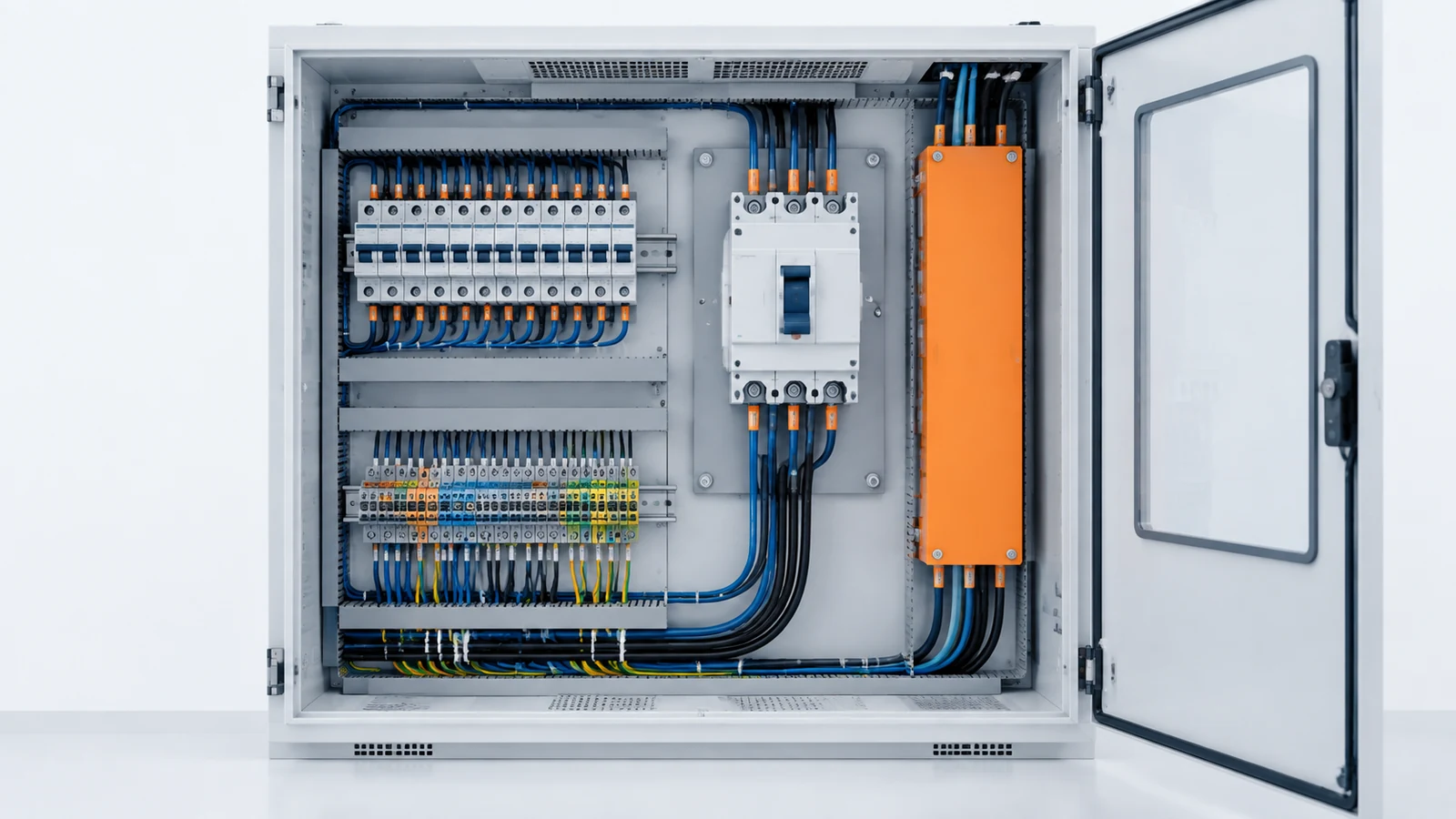
Review these points before finalizing a power distribution enclosure or an industrial automation enclosure:
- Breaker and accessory dimensions;
- Busbar, terminal, and conductor routing;
- Heat generated by the breaker and nearby devices;
- Clearances, separation, and insulation requirements;
- Door, cover, and handle access;
- Maintenance and test access;
- Cable-entry location and bend radius;
- Required environmental protection; for outdoor installations, confirm the outdoor electrical enclosure is suitable for the actual environment;
- Labels, warnings, circuit identification, and documentation;
- Space for future expansion, if required by the project.
For an enclosure RFQ, send the breaker model or electrical specification, system voltage, normal current, fault level, pole count, accessories, quantity, mounting arrangement, cable-entry requirements, environmental conditions, and required enclosure dimensions. If the project includes multiple enclosure types, start from the relevant electrical enclosure applications page and then confirm the exact mechanical and electrical requirements.
Circuit Breaker FAQs
Can I reset a tripped circuit breaker immediately?
Only reset it when it is safe to do so and the cause is understood or the equipment has been checked. Repeated trips require investigation, not repeated resets.
Is an MCB the same as an MCCB?
No. Both can provide overcurrent protection, but they differ in size, typical current range, trip-unit options, accessories, and system application. Follow the manufacturer’s ratings and the project requirements.
Does every circuit breaker protect against electric shock?
No. Overcurrent protection and shock protection are different functions. A standard overcurrent breaker should not be presented as a residual-current or ground-fault device unless it is specifically designed and identified for that function.
What is breaking capacity?
Breaking capacity, interrupting capability, or interrupting rating refers to the fault current a device is rated to interrupt under specified conditions. It is different from the breaker’s normal rated current.
Can an AC breaker be used on a DC circuit?
Not automatically. Confirm the manufacturer’s DC voltage, current, polarity, interrupting, and application ratings first.
When should a circuit breaker be replaced?
Replacement may be necessary after damage, failed testing, repeated unexplained operation, overheating, worn contacts, obsolete accessories, or a change in system requirements. A qualified person should determine whether the problem is the breaker, wiring, connected equipment, or protection design.
Final Circuit Breaker Selection Checklist
Before specifying or purchasing a breaker, confirm:
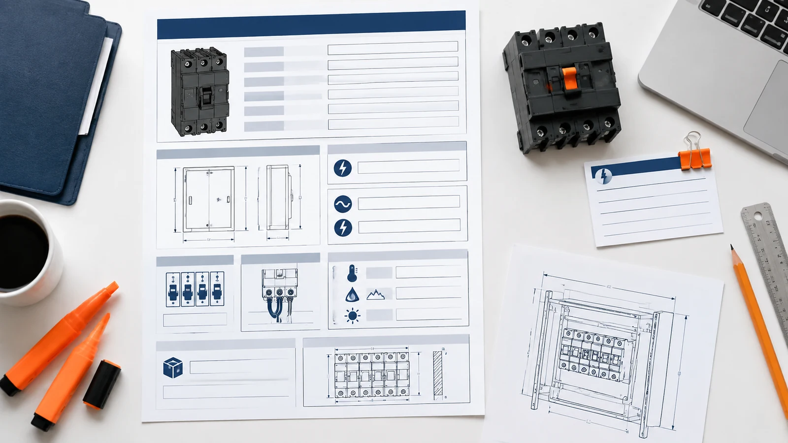
- AC or DC system;
- System voltage and phase arrangement;
- Normal and continuous load current;
- Inrush or starting current;
- Available short-circuit current;
- Required interrupting or breaking rating;
- Number of poles and neutral requirements;
- Overcurrent, residual-current, ground-fault, or arc-fault function;
- Trip characteristic or electronic settings;
- Coordination and selectivity requirements;
- Conductor, terminal, and busbar compatibility;
- Ambient temperature and altitude;
- Enclosure dimensions, heat dissipation, and service access;
- Required accessories, alarms, interlocks, and communication functions;
- Applicable project, regional, manufacturer, and safety requirements.
Conclusion
A circuit breaker does five jobs in sequence: it detects a defined abnormal condition, releases its mechanism, separates the contacts, controls the arc, and interrupts the circuit.
The type names describe different things. MCB and MCCB describe product families. ACB and VCB describe breaker designs used in different system contexts. RCD, RCBO, GFCI, and AFCI describe specialized protection functions.
For selection, start with the fault you need to control—not with the amp number printed on the handle. Then verify system voltage, normal load, available fault current, interrupting rating, trip behavior, coordination, terminals, enclosure conditions, and maintenance access.
If you are preparing an enclosure or panel RFQ, send the breaker specification, system conditions, layout or dimensions, cable-entry requirements, environmental conditions, quantity, and target application. That gives the enclosure design a real electrical context instead of forcing it to work from a product label alone.
Sources and Further Reading
Schneider Electric — Different types of circuit breakers explained
UL Solutions — Molded Case Circuit Breaker Marking and Application Guide