

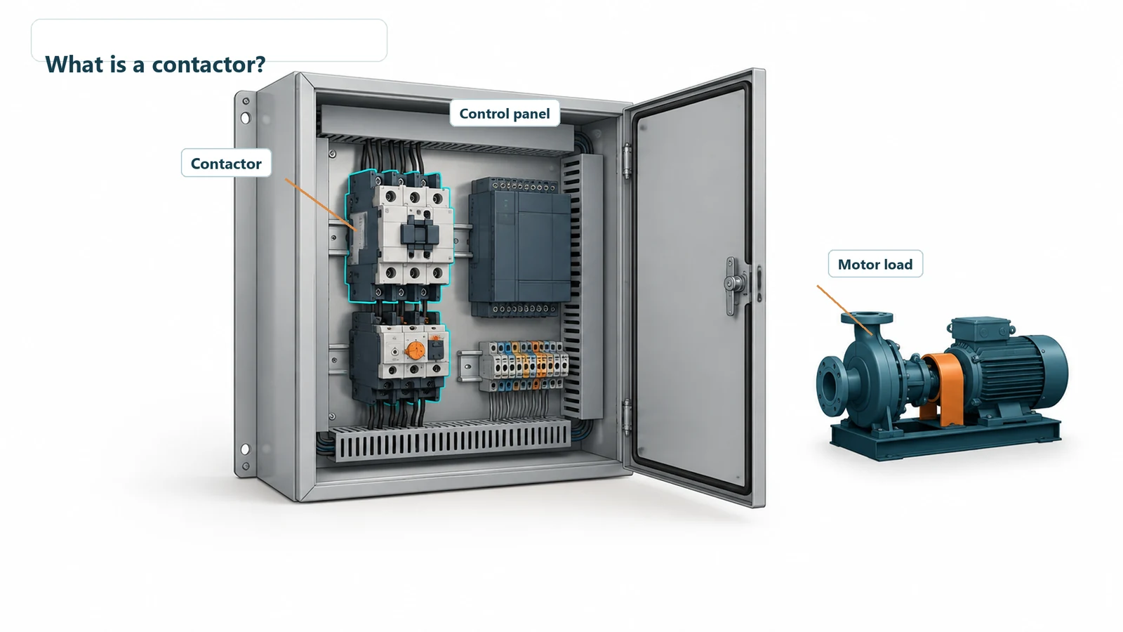
A contactor is an electrically controlled switch that turns a power circuit on or off. In a conventional electromagnetic contactor, a coil moves the main contacts, allowing a small control circuit to operate a larger load, such as a motor, heater, or lighting circuit.
Take a pump as an example. The controller sends the start command, while the contactor connects power to the motor. The motor current flows through the contactor’s main contacts, keeping that load off the controller’s output.
If you’re planning a control panel, it helps to understand both sides of this arrangement: how the contactor switches the load, and what space and connections it needs inside the enclosure.
How does a contactor work?
A conventional contactor has a coil, a moving armature, and main contacts. Many also have auxiliary contacts for control signals. In a typical non-latching design with normally open main contacts, the sequence looks like this:
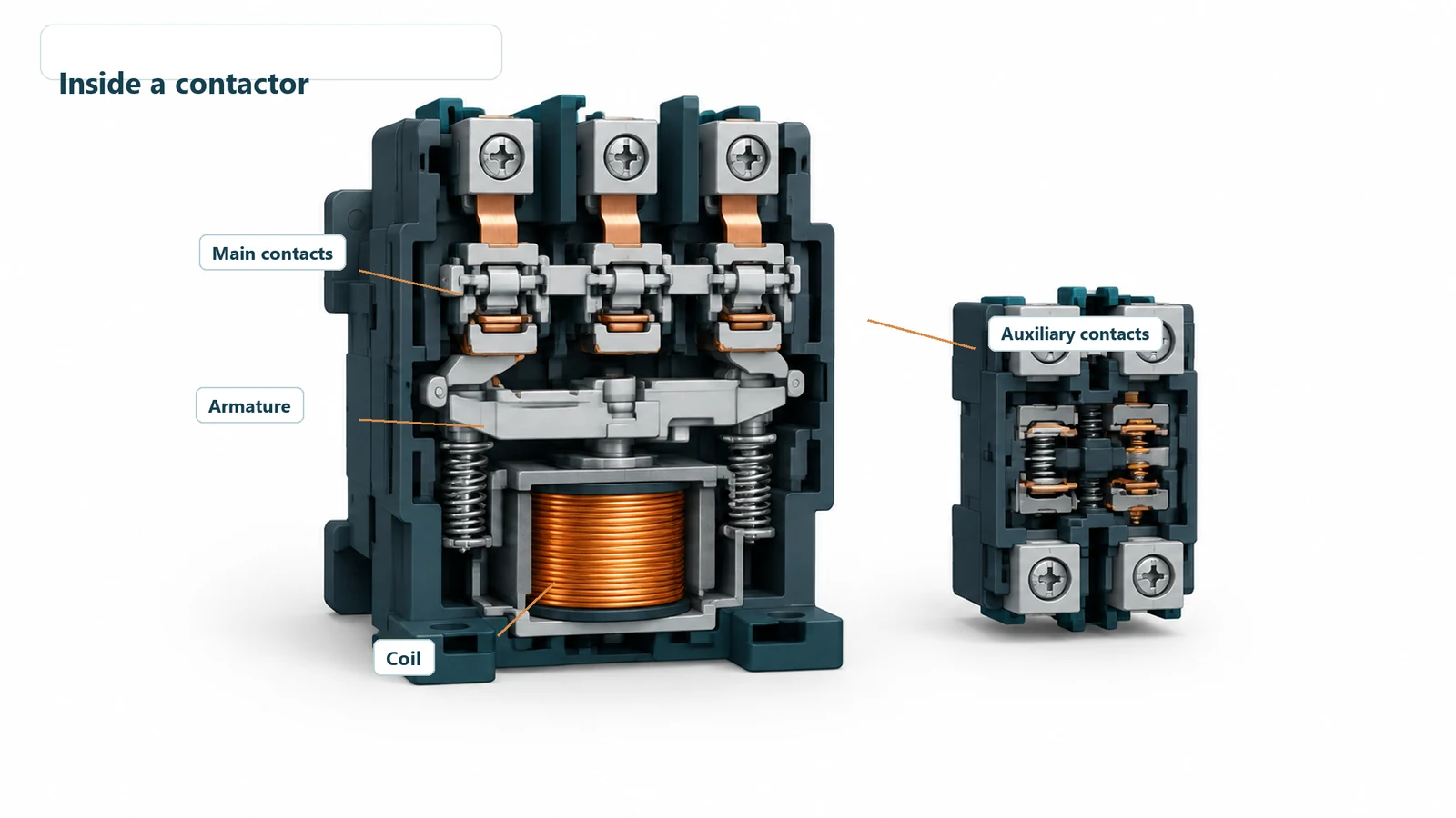
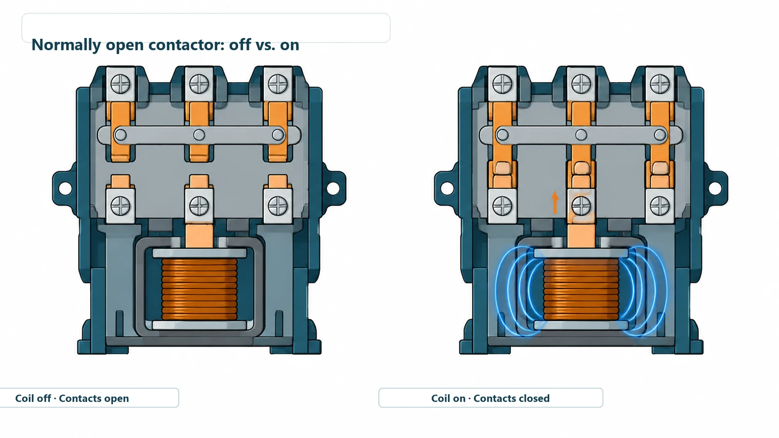
- The control circuit energizes the coil.
- The coil creates a magnetic field that pulls the armature into position.
- The main contacts close, connecting power to the load.
- When the coil is de-energized, the mechanism returns and the main contacts open.
The coil voltage and the load voltage are separate ratings. For example, a contactor can have a 24 VDC coil and switch a 400 VAC motor circuit. The selected device needs the correct rating for each side.
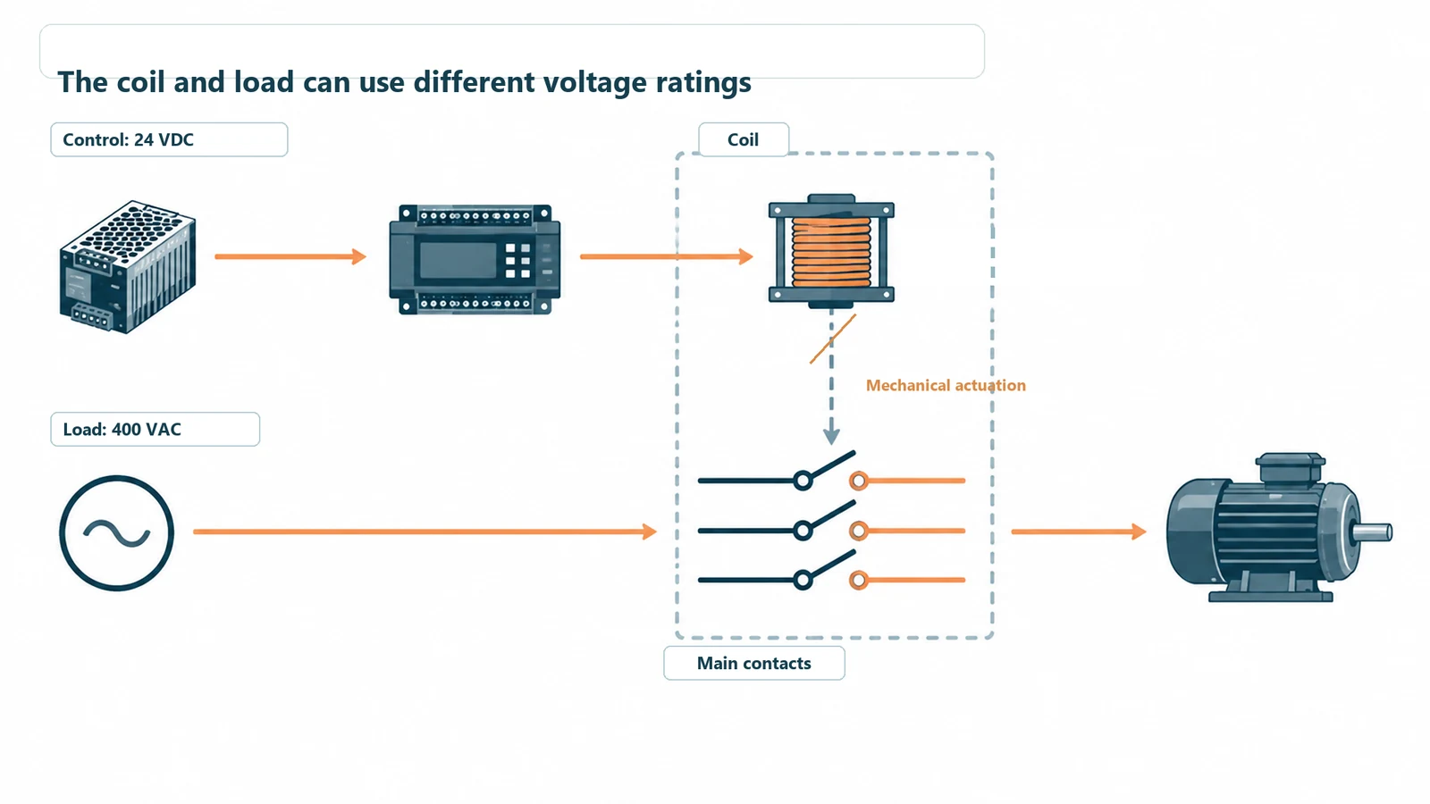
That’s why “24 V contactor” is an incomplete description when you’re ordering a replacement. You also need the main-circuit voltage, load rating, pole arrangement, and intended duty.
Latching contactors retain their state differently. For those devices, follow the model’s operating description rather than assuming that removing coil power opens the contacts.
Where does it fit in a control panel?
Think about what needs to happen when a motor starts. A pushbutton circuit or PLC issues a command. The contactor switches the motor circuit. Protection devices respond to overloads and faults, while auxiliary contacts can return a status signal to the control system.
Each part has a specific job:
| Part | What it does | What matters when you specify it |
|---|---|---|
| Coil | Receives the control command | AC or DC supply, voltage, coil consumption, and control-supply capacity |
| Main contacts | Switch the load current | Load type, operating voltage, current, poles, and switching duty |
| Auxiliary contacts | Support status signals and interlocks | Required normally open or normally closed contacts and their intended use |
| Overload and short-circuit protection | Provide protection around the switching device | Motor and circuit requirements, protective-device selection, and coordination |
These functions need to work together. In a traditional magnetic motor starter, a contactor is paired with an overload relay. The contactor switches the motor, while the overload relay provides motor-overload protection.
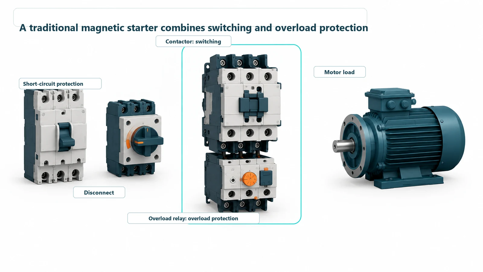
For safety monitoring, an ordinary auxiliary contact is not proof that every main contact has opened. Safety designs use suitable feedback devices, such as specified mirror contacts, as part of the complete safety circuit.
Contactor vs. relay, circuit breaker, and motor starter
If you’re reading a panel drawing or a supplier’s quotation, these names tell you which function each device provides.
| Device | Main job | What that means for your panel |
|---|---|---|
| Contactor | Remote switching of a power load | Lets the control circuit start and stop the connected equipment |
| Control relay | Switching control signals and smaller loads | Handles signal logic or loads within its ratings |
| Circuit breaker | Interrupting overcurrent and short-circuit conditions | Provides circuit protection according to the selected device’s characteristics |
| Traditional magnetic motor starter | Combining a contactor with motor-overload protection | Provides motor switching and overload protection in one arrangement |
| Disconnect or isolator | Providing a means of separation | Handles the isolation function required for the application |
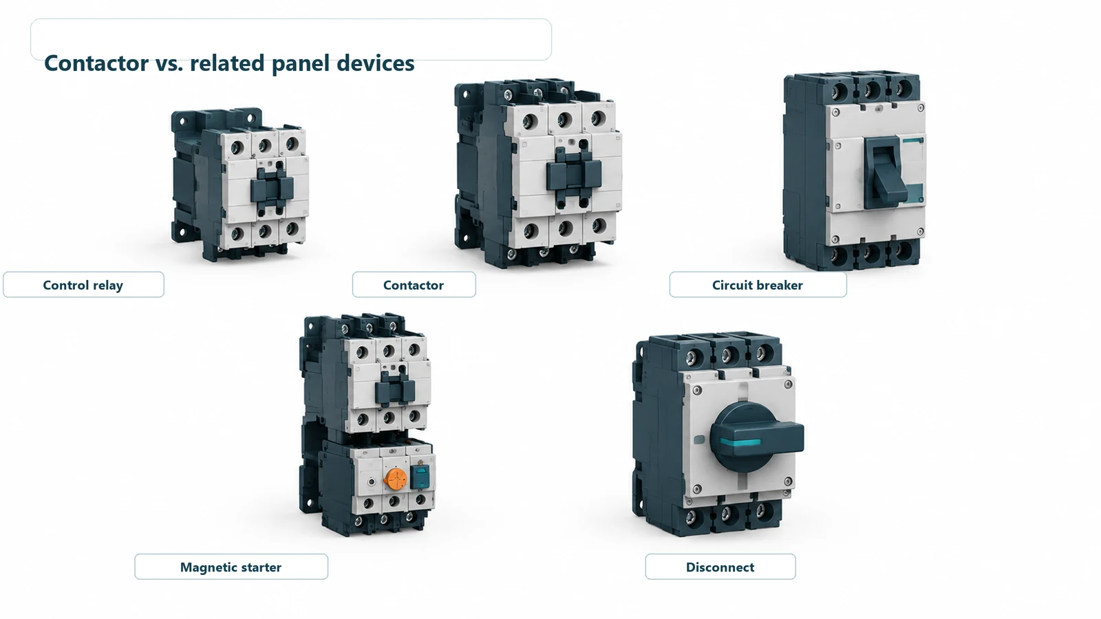
There isn’t a universal current threshold where a relay becomes a contactor. Their ratings overlap. Compare the intended service and manufacturer’s ratings rather than choosing by size or the ampere number alone.
A contactor’s normal stop command also doesn’t replace the isolation procedure needed for maintenance.
What are contactors used for?
Common uses include pumps, fans, compressors, electric heaters, and lighting circuits. The control input may come from a PLC, a thermostat, or a pushbutton circuit.
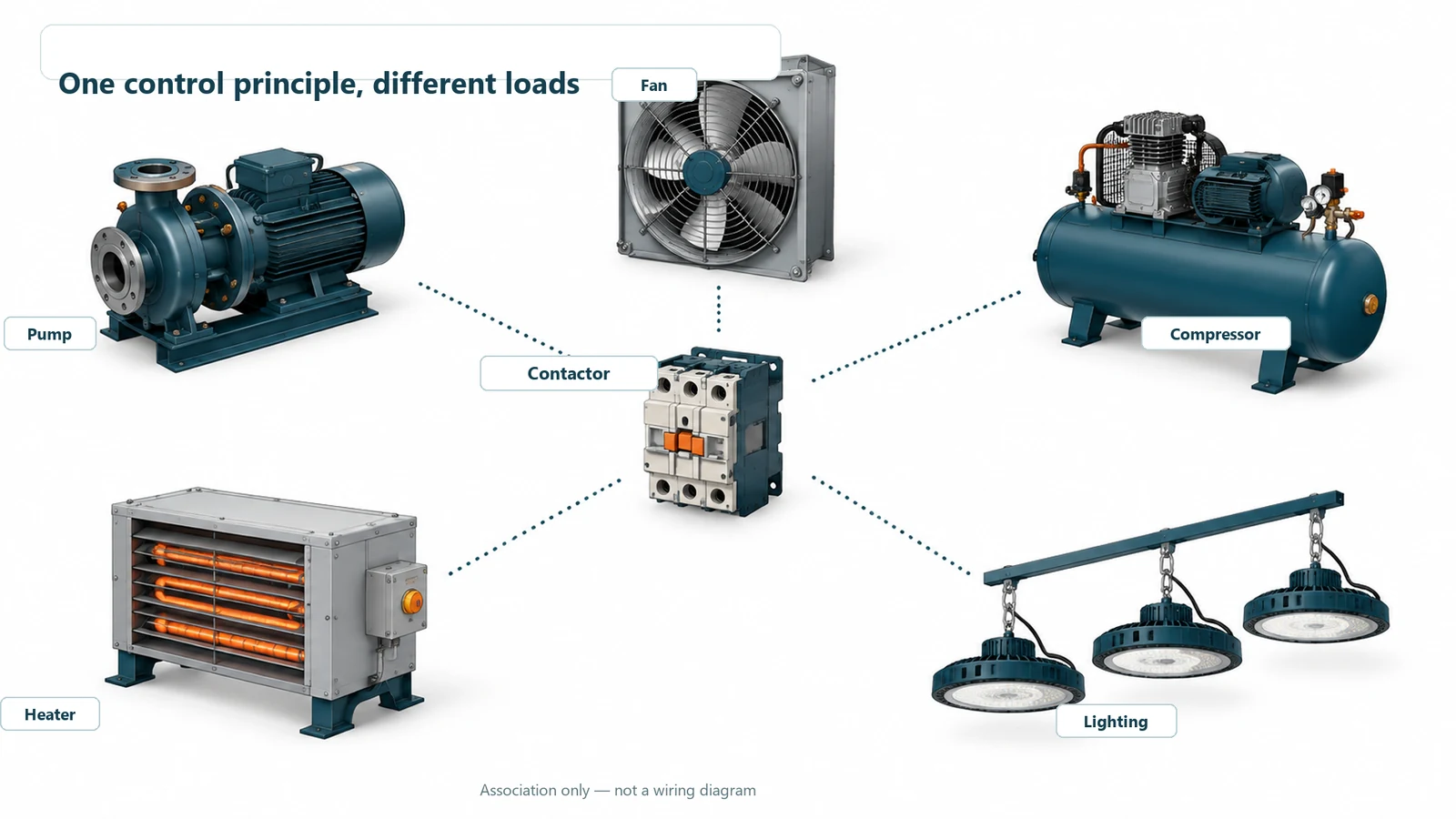
The load changes the selection. Starting a motor places different demands on the contacts from switching a resistive heater. Lighting equipment can also have substantial inrush current. A contactor suitable for one application may have a different usable rating in another, which is why its load category matters.
How do you choose a contactor for your panel?
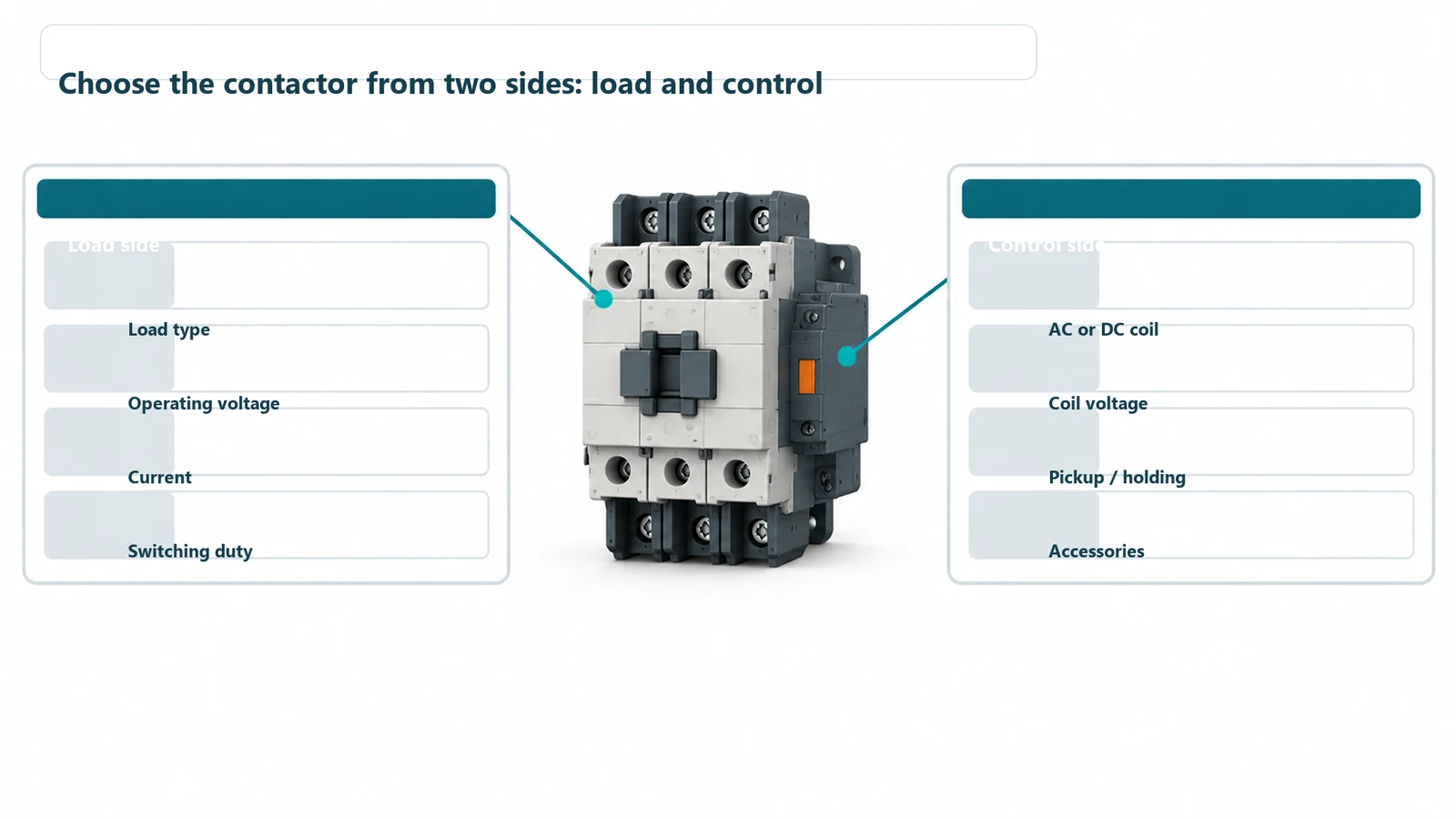
Start with the equipment you’re controlling. Then check the control supply and physical arrangement. That order makes it easier to compare devices that actually suit the job.
Match the load and switching duty
Record the load type, operating voltage, current, and number of poles. Include how often the equipment starts and stops. Starting current and repeated switching affect the duty the contacts must handle.
When comparing two models, use their ratings for the same load category and voltage. Two contactors with similar headline current ratings can be intended for different duties.
Check the coil and control supply
Look at the coil’s AC or DC rating, voltage range, pickup and holding requirements, and suppression provisions. The control supply needs to support the coil when it pulls in as well as when it stays energized.
This also matters when you replace a device. Matching the main-contact rating leaves the coil, control output, and accessories to check. Keep those details together on the component list.
Plan the contacts, protection, and layout together
List the auxiliary contacts needed for status signals and interlocks. Identify the overload and short-circuit protective devices alongside the contactor, so the electrical design covers the complete circuit.
Then look at the layout with the accessories included. Can the installer reach the terminals? Is there room for the conductors to bend? Can the contactor be removed without dismantling the surrounding equipment? These are useful questions to settle before the mounting plate is made.
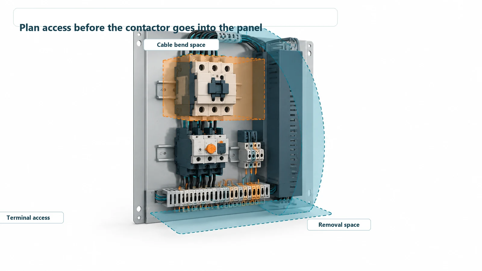
Coil heat and neighboring equipment also belong in the thermal review. Use the component manufacturer’s mounting and clearance requirements when arranging the panel.
Why does a contactor chatter or fail repeatedly?
Repeated contactor damage is a reason to look beyond the replacement part. Low control voltage, an unsuitable switching duty, loose connections, and heat can all affect operation.
An EPRI investigation documented a 40 HP, 460 V compressor whose contactor had repeatedly burned and welded closed. Replacing the motor had not solved the problem. During startup, voltage at the compressor fell from 442 V to 323 V, while the nominal 115 V control supply fell from 117 V to 84 V. The investigator linked the contactor bounce to the low control voltage during starting.
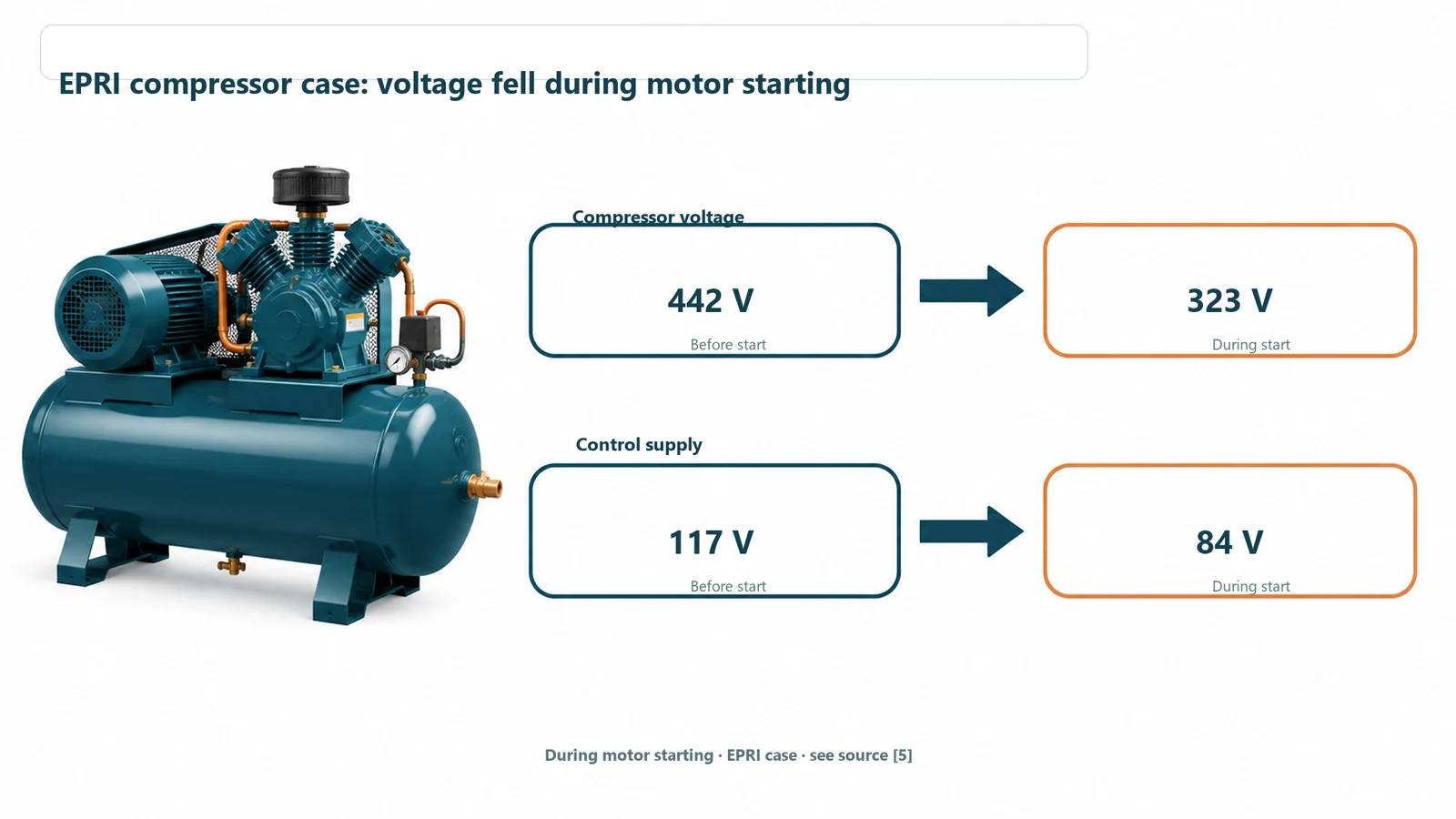
For a similar symptom, have a qualified technician investigate the control supply during startup before replacing the contactor again. A reading taken while the motor is idle can miss the condition described in that case.
Getting the enclosure right around the contactor
The device dimensions are only part of the space you need. The layout also has to accommodate the overload relay, auxiliary blocks, wiring ducts, terminals, and cable bends. Door-mounted devices need room behind them when the door closes.
Ask your panel builder to show those details on the layout you send for enclosure review. For an industrial automation enclosure, that gives us a useful starting point for reviewing mounting features and access before fabrication.
Agree the mounting points and cutouts before fabrication
At FN Enclosure, we manufacture cabinet bodies, doors, and mounting plates to approved drawings. Our custom electrical enclosure review covers mounting positions, cutouts, cable entries, door and gasket fit, material, and finish.
A gland-plate change is easier to make on a drawing than on a finished cabinet. Before production, we review opening coordinates, component clearances, and service access with you, so you can resolve fit issues while the layout can still change.
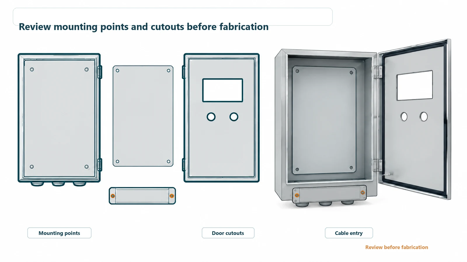
The review also connects the outside of the cabinet with what’s inside. Door cutouts need to suit the devices behind them; cable-entry positions need to work with the internal layout. Bring both sets of details into the same review.
Start with the information you have
You can begin with a CAD or PDF drawing, a preliminary component layout, a sketch, or a sample photo. Mark any components that are still undecided. We can discuss the enclosure requirements while you finish the component selection, then finalize the mounting dimensions before fabrication.
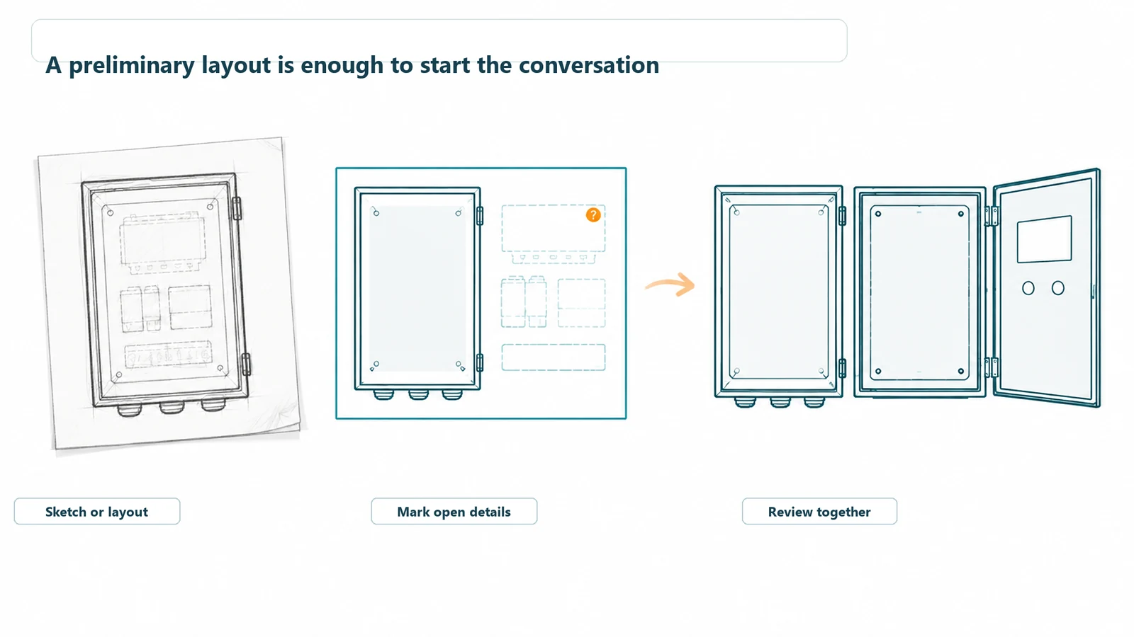
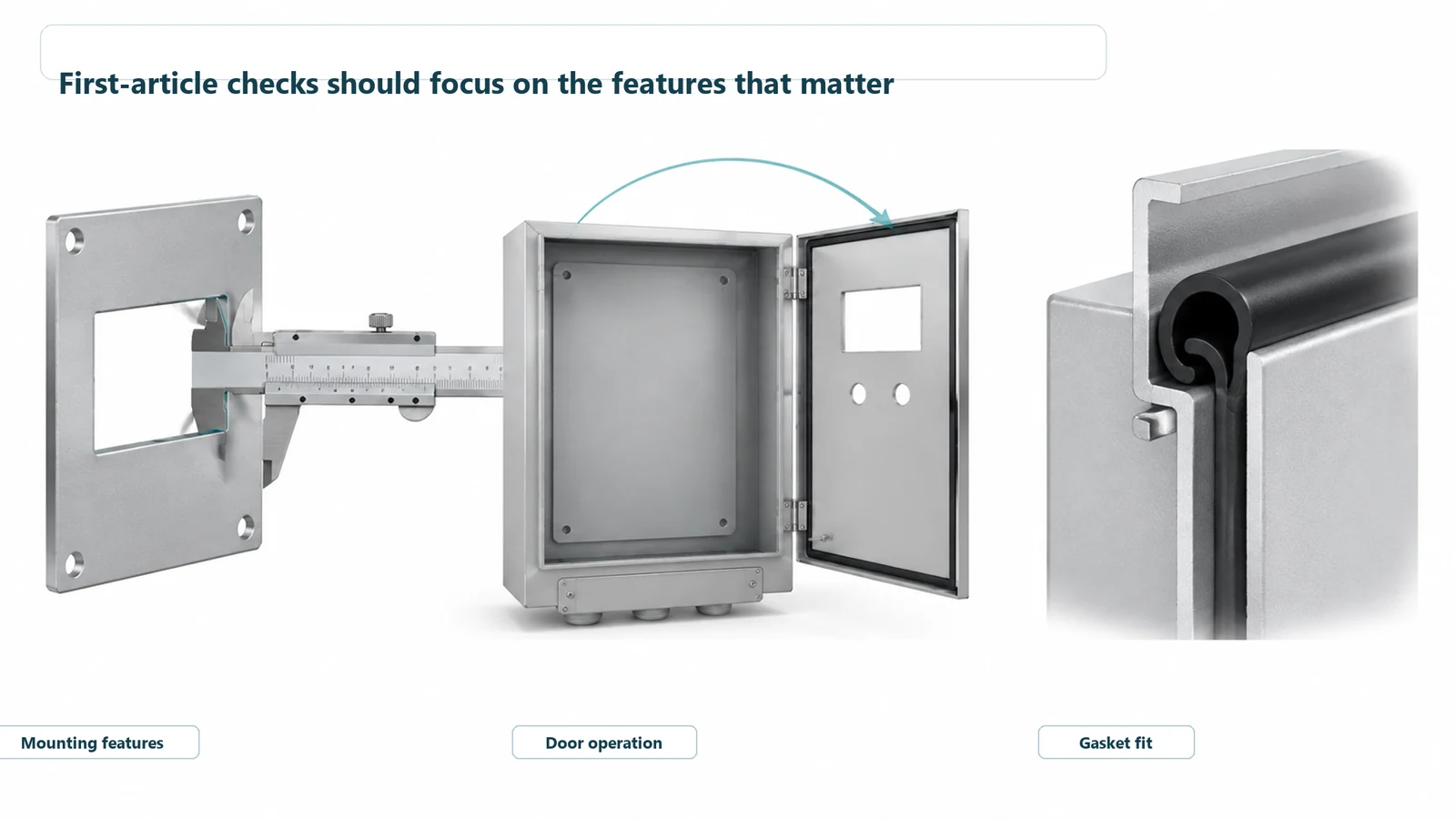
For a new design, first-article checks can cover mounting holes, door operation, cutouts, gasket fit, and finish before batch production is approved. That gives you specific features to review against the drawing rather than relying on an overall cabinet photo.
Your panel builder handles the electrical design and wiring; FN supplies the enclosure and agreed mechanical features. The quotation sets out the included parts and work, keeping the handoff between the two clear.
FAQ
Is a contactor the same as a relay?
They use similar switching principles. Contactors are generally designed for power-load switching, while control relays commonly handle signal logic and smaller loads. Choose using the actual load and device ratings; there is no universal ampere cutoff between them.
Does a contactor protect a motor from overload?
A standard contactor switches the motor circuit; overload protection comes from an overload relay or another suitable protective arrangement. A traditional magnetic starter combines the contactor and overload relay.
Can a 24 VDC coil switch a 400 or 480 VAC load?
Yes, if the contactor is rated for that combination. Check the coil rating and the main-contact rating separately. The main contacts also need to suit the load type and current.
Does an auxiliary contact prove that the main contacts are safely open?
An ordinary auxiliary contact does not provide that proof. Safety feedback needs the appropriate contact arrangement, such as specified mirror contacts, and a safety circuit designed to monitor it.
Do I need a finished panel drawing before contacting FN?
No. Send your preliminary layout or component list and mark the details still being decided. We can begin the mechanical enclosure discussion from there. Final dimensions and mounting details are settled before fabrication.
Planning an enclosure for your control panel?
Send us your layout or project requirements. Include the component list, available space, quantity, and installation environment. If you already have cable-entry or door-cutout drawings, include those too.
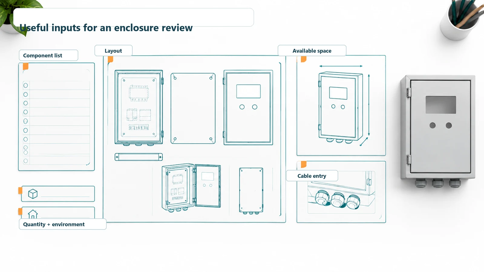
We’ll use those details to review the enclosure’s mounting arrangement and openings with you before production release.