

For HMI enclosure mounting, start with where the operator needs to stand. A wall mount suits a fixed working position beside a suitable supporting structure. A pedestal gives the operator station its own location in the process area. A support arm is useful when the screen must move between working positions or needs adjustment beyond a simple tilt.
These arrangements can overlap. Wall and pedestal describe the support location; a support arm describes the mechanism between that support and the enclosure. A wall-mounted arm or a pedestal with a swivel head may therefore be the right arrangement.

Choose the arrangement around the operating position
| Operating scenario | Best starting arrangement | What the drawing needs to show |
|---|---|---|
| The operator normally stands in one place beside a suitable wall | Fixed wall bracket, or a tilt/swivel bracket if only the viewing angle changes | Supporting structure, mounting height, enclosure orientation and service clearance. |
| The station needs its own position within a process area | Floor-mounted pedestal or a suitable freestanding stand | Floor position, base arrangement, cable entry and surrounding access space. |
| One interface must serve the front and rear of a machine | Support arm with enough reach and suitable joints | Both working positions, the path between them, rotation limits and cable route. |
| Operators need substantially different screen heights | Mount with a specified vertical adjustment range | Lowest and highest working positions, keyboard position and how the mount holds its setting. |
A separate parking position can matter too. An HMI that is reachable during production may still block a machine door during setup. The mounting layout should show the operating, parked and maintenance positions that the task actually requires.
Wall mounting: when the operating position stays fixed
A nearby wall is useful when it places the screen within comfortable reach of the operator’s normal position. If the screen only needs to face slightly left, right, up or down, a short pivot or tilt bracket may provide enough adjustment. ROLEC’s guide to mounting HMI, panel and command enclosures and Hope Industrial’s fully enclosed monitor mounting guide describe these simpler arrangements alongside longer arm systems.
That distinction helps avoid unnecessary reach. A fixed bracket holds the enclosure close to the supporting surface. An arm moves the screen farther into the working area, but also creates a larger swept area and increases the leverage on its base. Adding an arm is justified when that extra movement solves an access problem.
The supporting surface matters as much as the visible bracket. A machine cover panel and the frame behind it are different mounting points. Where a cover cannot carry the assembly’s loads, the connection needs to transfer those loads into a suitable structure. Showing the wall or machine construction on the mounting drawing makes that load path clear.

A rear-opening enclosure needs enough wall clearance for the cover and service work; otherwise, a close wall mount is unsuitable.
Pedestal mounting: when the station needs its own location
A pedestal lets the HMI position follow the process layout. It is a useful starting choice when operators need a fixed station near the equipment they control, without placing it against a wall. The screen can remain at one location while the pedestal carries cables down toward the floor or another connection point.
Envirogen’s case study of J. Wray & Nephew’s distilled-water plant describes a pedestal-mounted HMI in the center of the plant for viewing and controlling process information, including valves, tank levels and pressure.
The base changes how the station occupies the floor. A floor-anchored pedestal transfers its loads through the baseplate and anchors. A freestanding stand relies on its own base geometry and weight for stability. These arrangements cannot be exchanged merely because the enclosure connection looks similar. ROLEC describes a freestanding base, while Hope’s pedestal arrangement uses floor anchoring.

For a fixed pedestal, the useful layout includes the operator’s standing space, the base and the enclosure’s service area. Placing the screen at a convenient height does not help if the base occupies an aisle or the rear cover opens into nearby pipework.

Support arms: when the screen needs to move
An HMI support arm earns its place when the operator needs the same interface in more than one position. Strongarm’s C&B Machinery mounting case describes a pendant that moves from the front operating position of a grinding machine to the rear setup position. That is a specific reach requirement that a fixed wall bracket cannot meet.

The type of movement matters. Horizontal swivel changes where the screen sits around a support. Display tilt changes the viewing angle. Vertical adjustment changes screen height. A jointed arm may provide one or two of these movements without providing all three, so a long reach alone does not establish suitability for operators of different heights.

Draw the route between the required positions. A screen may reach both ends of its travel while its enclosure, keyboard tray or handle strikes a guard along the way. The arm also needs a position where it can stay clear during machine access. Joint limits and the available cable movement belong in that same layout.
Choose the shortest reach and fewest joints that satisfy the working positions. Extra joints can add useful movement, but they also change the assembly’s load capability. ROLEC’s arm configuration guidance explicitly warns that longer profiles and additional joints can reduce the permitted load.
Why weight and reach must be specified together
The load on an HMI mount includes everything it carries: the enclosure, installed HMI and controls, plus any keyboard tray, handles or other attached equipment. Hope Industrial’s configuration guide identifies monitor-and-keyboard combinations that exceed one of its arm options. The display’s weight on its own would therefore give the wrong answer.
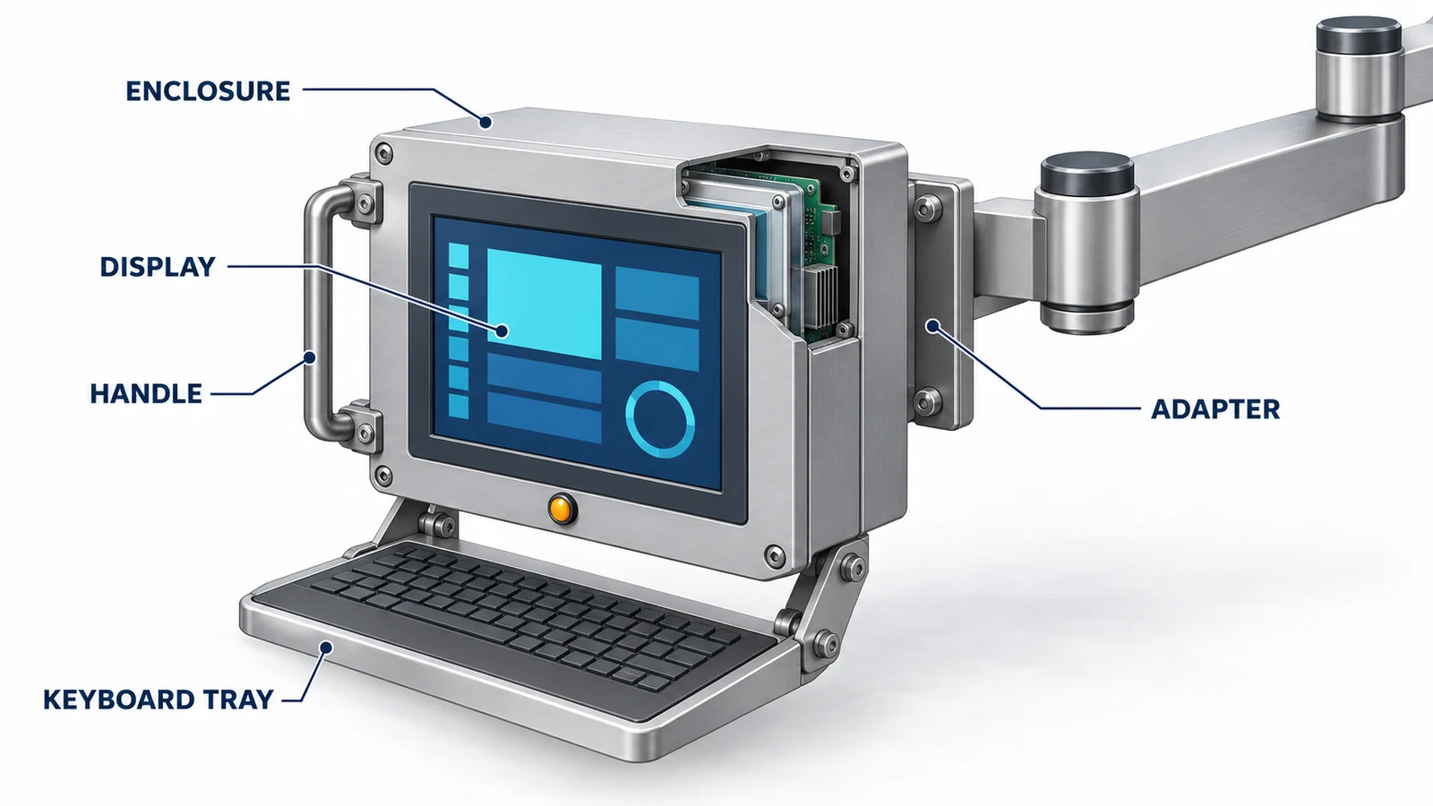
Reach changes the mechanical demand. Moving the loaded enclosure farther horizontally from a supporting joint increases the bending moment produced by its weight. Accessories can shift the combined center of gravity, so the load’s position relative to the joint matters as well as the arm’s nominal length. The relevant input is the horizontal distance from the joint to that combined center of gravity.

A supplier’s headline capacity is only useful with the configuration it describes. The relevant load data must match the selected arm length, joints, base orientation and enclosure connection, as outlined in ROLEC’s suspension-arm selection guide. Rittal’s support-arm overview states its load levels relative to a specified jib length. That condition is part of the rating.
On a pedestal carrying an arm, increasing the horizontal offset of the combined load also increases the moment at the base. The arm’s load rating alone cannot establish whether a freestanding base is stable or an anchored base is adequate.
Match the enclosure connection to the cable route
The enclosure-side interface may be a rear mounting pattern, a bottom flange or a dedicated adapter. METCASE’s TECHNOMET-CONTROL enclosure illustrates the distinction: it has a rear VESA interface as standard, while a modified version can accept a support arm through the base panel.
Changing the attachment side changes where the support sits relative to the enclosure’s weight, rear cover and cable entry. A useful interface drawing therefore shows the mounting face, hole or flange geometry, fastener engagement and cable passage. Matching the hole pattern establishes one part of the fit; it does not establish the capacity of the complete support assembly.

For an HMI support arm enclosure with internal cabling, the cable passage must work through the adapter and joints as well as the straight arm sections. A cable may fit through the profile while its fitted connector cannot pass through a joint. That difference determines whether the cable can be pulled through, whether covers must open for installation, or whether a different connection arrangement is needed.

Teguar’s food-processing panel-PC case brings these decisions together: the application required a swing-arm installation with cables routed inside the arm, and the selected computer configuration had to match the customer’s mounting infrastructure. Cable routing was part of the hardware choice.
Movement adds another constraint. The cables need enough freedom for the permitted travel without becoming trapped or tensioned. An external route also needs a defined path so that excess cable does not enter a machine opening or catch on nearby equipment. The arm’s usable movement ends wherever the cable arrangement can no longer follow it safely.
Leave space to open and service the enclosure
As VarTech explains in its guide to mounting industrial computers in confined spaces, the enclosure needs space for service as well as normal operation. A rear door needs room to swing; a removable panel needs room to come away from the enclosure. The technician also needs access to the fasteners, connectors and any component being replaced. A small gap behind a closed box does not necessarily provide that access.
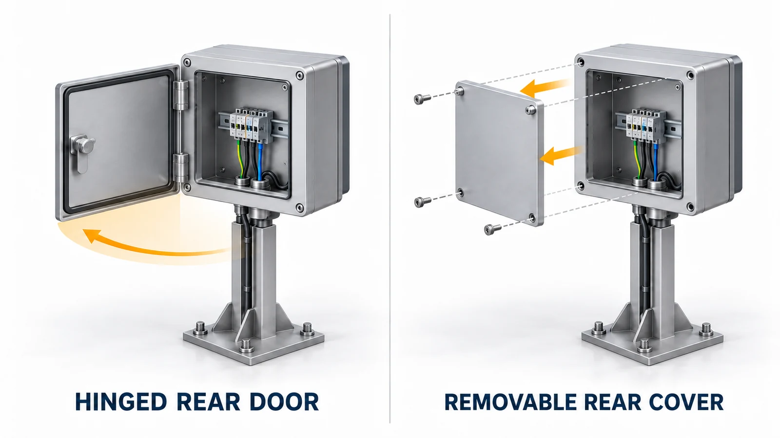
Armagard’s Florette workstation case describes enclosure workstations installed on stands with front and rear access. For that arrangement, positioning the rear against another machine would remove part of the access the enclosure was designed to provide.
Show the open door or removed cover on the layout. If the HMI must swing aside for maintenance, include that position and the cable movement needed to reach it. This makes the service requirement visible before the mounting holes and cable entries are fixed.
Turn the layout into an enclosure brief
At the early selection stage, a layout sketch is enough to establish the operating positions, available support and required movement. The interface drawing becomes useful once a bracket, pedestal or arm has been selected. Together, those documents explain where the enclosure belongs and how it connects.
For quotation, add the complete mounted weight, cable route and service position to the selected support’s interface drawing. State who supplies the enclosure, adapter, arm or pedestal, and who installs the assembly. That avoids treating an enclosure with mounting provisions as an order for a complete support system.

For an FN project, the industrial automation enclosure page outlines the mechanical enclosure scope. Once the mounting arrangement is defined, use FN’s contact page to arrange an enclosure review and email the layout and selected support’s interface drawing.
We fabricate the enclosure body itself — cutouts, mounting pattern and cable entry machined to your drawing. See wall-mounted electrical enclosures. These housings are built to order rather than stocked from a catalog, so send the arm or pedestal part number or drawing you are working to and we machine the mounting pattern, VESA interface and cable entry to match it.
FAQ
Can an HMI support arm be mounted on a wall?
Yes, an arm can connect an HMI enclosure to a suitable wall or supporting structure. The wall attachment must carry the complete assembly, and the layout must leave room for its movement and service access.
Does a longer HMI arm also provide height adjustment?
A longer arm does not automatically provide height adjustment; a fixed-height swivel joint may only move the screen horizontally. Choose a mount with a specified vertical adjustment range when the working height must change.
Is a matching VESA or hole pattern enough to confirm compatibility?
Matching holes establish the attachment layout, but do not establish load capacity or enough space for cables and service. The selected adapter and support must suit the complete assembled station at its intended reach.
Can I keep the existing arm after adding a keyboard tray?
Only if the selected arm configuration still supports the complete assembly at the required reach. The tray and keyboard add weight and may shift the combined center of gravity, so a load check based on the display alone no longer establishes suitability.
What should I send for an HMI mounting-interface review?
A layout sketch should show the operating and service positions, available support and required movement. Once the mounting hardware is selected, add its interface drawing, the complete mounted weight and cable route. State who supplies the enclosure, adapter and support so the request defines the intended supply scope.
Sources
- ROLEC: How To Mount HMI, Panel And Command Enclosures
- Hope Industrial: Configuring a Fully-Enclosed Universal Mount Monitor, Part II
- Envirogen: J. Wray and Nephew distilled-water plant
- Strongarm: C&B Machinery operator-interface mounting
- ROLEC: Configure the Best Modular Suspension Arms
- METCASE: How to Specify TECHNOMET-CONTROL
- Teguar: Food-process hardware collaboration case study
- Armagard: Florette enclosure workstations
- VarTech: Mounting Industrial Computers in Confined Spaces
- Rittal: Support Arm Systems
- ROLEC: Which Modular Suspension Arm Is Best for My Industrial Electronics?