

To bay modular electrical enclosures, establish a common reference for the cabinet frames, use the joining hardware and seals specified for that interface, and plan the cable crossings before closing the joint. If the lineup will ship in sections, decide where it separates before wiring begins.[1][2]

Keep the enclosure drawings and the applicable baying-kit instructions at the assembly area. They should identify the fastening positions, tightening requirements and sealing details. Resolve the missing information before the joint becomes difficult to reach.
For populated equipment, qualified personnel should handle electrical isolation, disconnection and recommissioning. Keep the cabinets secured against tipping or sliding during assembly and panel removal, following the manufacturer’s handling instructions.[3]
Resolve the interface before assembly
Matching cabinet dimensions do not establish that two frames use the same joining interface. nVent’s PROLINE G2 range, for example, has different kits for side-to-side joining, front-to-back joining and connections to certain other frame profiles.[2]
When specifying modular electrical enclosures, ask for an interface drawing that identifies:
- The cabinet sequence and orientation, including which faces will meet.
- The frame connection points, joining parts and space needed to install them.
- The side panels to remove and any internal partitions to retain.
- The gasket path and how it meets the roof, rear and base details.
- The cable crossings and shipping-section boundaries.

Resolve missing gasket details and unfamiliar hole patterns with the enclosure supplier before assembly.
Establish one datum for frames and internal rails
Choose the reference points on the assembly drawing before positioning the cabinets. A useful arrangement identifies a common base level, a front frame plane and the reference height or hole position for components that continue across cabinets.
Check each cabinet against those references. If installers work only from the preceding cabinet, a position error can be carried into the next bay. Mark the agreed datum where it remains visible during assembly and record the measured positions required by the drawing.

Internal alignment needs its own check. In Rittal’s Schaper Steuerungstechnik case, the customer describes cable-clamp rails in adjacent enclosures being one hole out of alignment. The VX25 hole-counting system helps locate the intended mounting position. Specify the rail reference on your own assembly drawing; other enclosure systems may use a different hole pitch or indexing method.[1]
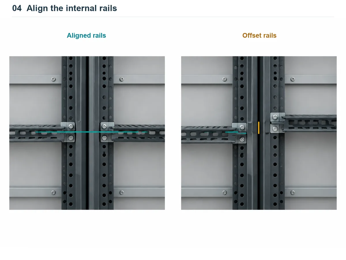
Before final tightening, compare the frame positions and the cross-cabinet rail or duct heights. If connection holes do not line up, narrow down the cause:
- If an entire cabinet sits high or out of plane, check its support and positioning first.
- If the frames align but a bracket or hole does not, check the part number, orientation and drawing revision.
Do not use the joining bolts to force an unexplained mismatch into place. Obtain the enclosure supplier’s correction method before modifying holes or brackets. The same check is worth repeating if a door that fitted before joining begins to bind afterward.
Prepare side panels and joining points while access is open
Identify the facing side panels that the baying arrangement requires you to remove. Keep the outer end panels and any internal partitions required by the design. Label removed parts by cabinet position so that they return to the correct location after transport.
A partition between cabinets can have a functional purpose. ABB’s cabinet-construction instructions for ACS880 multidrive modules in Rittal VX25 enclosures describe dividers used to separate cooling arrangements. That is a reason to check the thermal and electrical layout before treating an internal panel as spare material.[4]

Check the installation access as well as the finished fit. Can a technician reach every joining point with the specified tool after the mounting plates and wire ducts are installed? Can a seal be fitted without removing equipment again?
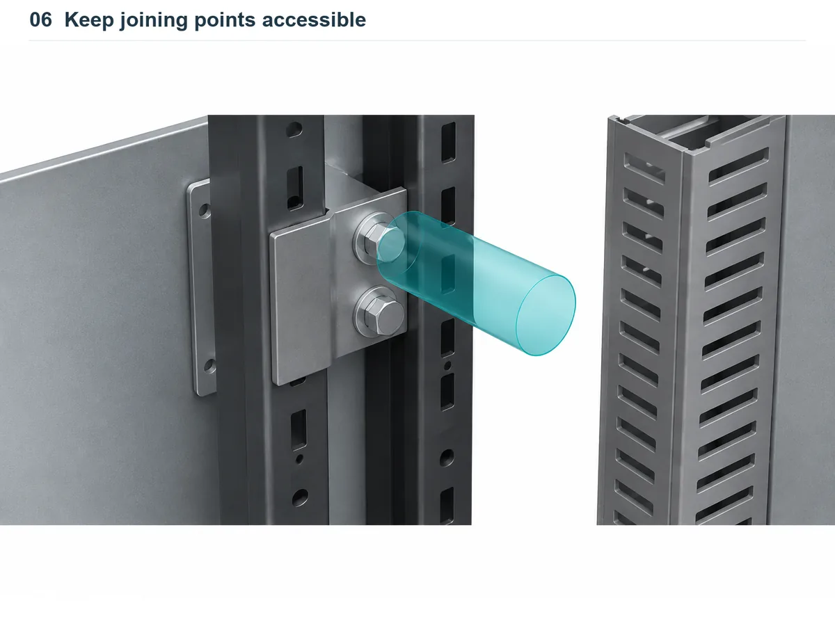
ABB also warns that baying parts must not obstruct later component installation in its reference design. Use that as a review question for your own layout: show the joining brackets, cable ducts and nearby equipment together, rather than approving each in a separate view.[4]
Where doors or panels need removal for access, note their bonding connections and the sequence for restoring them. Keep sealing edges protected while the parts are off the cabinet.[3]
Fit the joint seal before it becomes inaccessible
Confirm the gasket arrangement before bringing the frames together. In Rittal’s Duim techniek case, the baying seals are fitted before the enclosures are joined.[5]
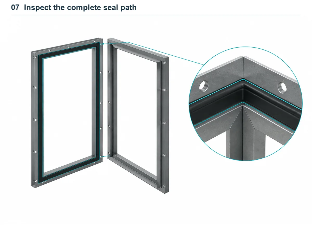
For PROLINE G2 P2AJ, horizontal and vertical gaskets differ, and a spacer controls compression. Select the gasket profiles and compression hardware specified for your joining kit.[2]
At the open joint, inspect the seating surfaces, gasket position and the transitions at corners. Follow the specified arrangement for joints or overlaps. Keep cables, debris and loose hardware out of the sealing path.
Follow the kit’s joining and tightening sequence. Stop if the gasket moves out of position, a specified spacer is missing or the mating faces cannot reach their intended position. Resolve the cause before tightening further.
For a lineup being rebuilt after shipping, check reused seals before closure. Rittal’s VX25 instructions require complete replacement of gaskets damaged in the contact-edge area. Use the replacement criteria for the actual enclosure system; separation alone does not establish whether a seal is reusable.[3]
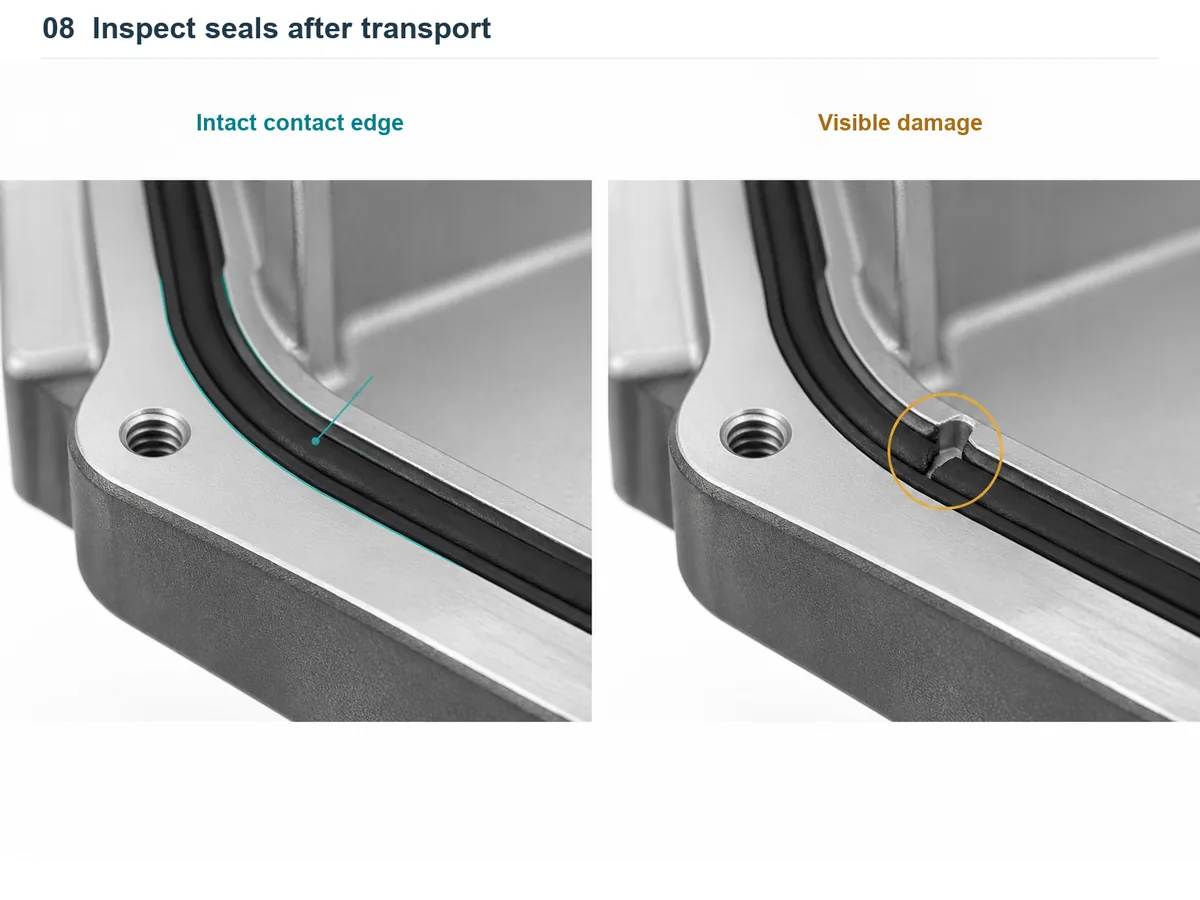
Confirm the required IP or NEMA Type against the documented joined configuration. A visual check can identify missing or displaced seals, but it does not establish the lineup’s protection rating.
Give each cross-cabinet cable route a defined path
Show the crossing location on the drawing before the cabinets are populated. Depending on the design, cables may pass through the open internal interface, through a defined partition opening or through a designed plinth route. Rittal describes plinth arrangements that carry cables beneath the installed equipment; nVent offers a specific sealed-plinth joining kit with cable-edge protection.[6][2]
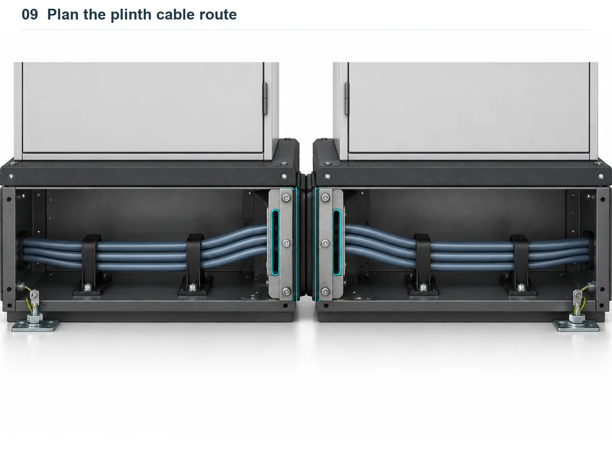
For each crossing, record the opening and support positions, the cable manufacturer’s bend-radius requirements and access for installation or replacement. Arrange support so that the cable weight does not hang from the terminations. Protect cables where they pass metal edges, and keep them clear of the enclosure’s mating and sealing surfaces.

Check the route with the covers and panels fitted in their final positions. An opening that is accessible during wiring may be difficult to reach after the adjacent cabinet and its equipment are in place.
Have the electrical designer specify circuit separation, electromagnetic compatibility (EMC) provisions and termination methods for the equipment being installed.
At a shipping split, identify how each crossing will be disconnected and restored. The electrical designer should specify the terminals, connectors or retermination procedure. The drawing should show where the installer works and which cable ends or connections must be identified.
Include the protective bonding arrangement in this review. Record which connections are disturbed by panel removal or shipping, and require their restoration and verification before electrical acceptance.[3]
Plan shipping sections before wiring
Mark the transport breaks on the same lineup drawing used for assembly. Decide which mechanical joints open, which cables disconnect and which parts travel separately before those interfaces are buried behind installed equipment.
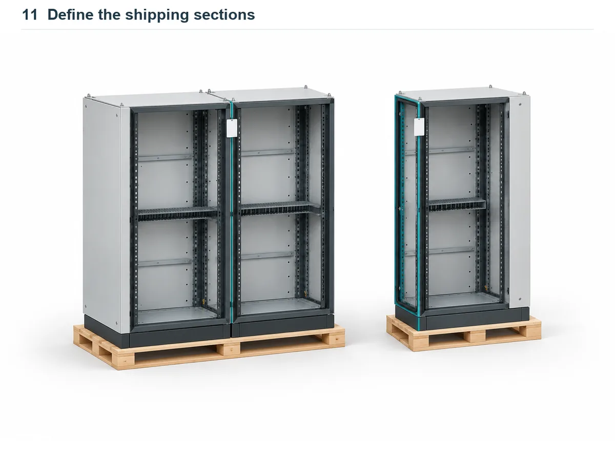
For the Gold Coast Airport expansion, IPD describes a switchboard exceeding 13 meters being built in several shipping sections for reassembly on site.[7]
Choose joining hardware with that sequence in mind. nVent’s PROLINE G2 P2AJJ uses a two-piece bracket designed to allow initial baying, separation for transport and field rebaying without removing the brackets.[2]
Record the factory fit-up before separation: cabinet order, interface identifiers, removable parts, seal condition and the cable-disconnection plan. Put the required replacement parts and site assembly instructions with the relevant shipping section.
Check handling separately. Rittal’s VX25 load-capacity documentation specifies combination angles for crane transport of bayed enclosures. For any populated shipping section, obtain the approved lifting arrangement and load limits for that configuration; do not infer them from the fact that its frames are bolted together.[8]
Check the rebuilt interfaces before electrical acceptance
Use the factory assembly records as the site reference. Give the installer acceptance criteria from the approved drawings and kit instructions, with a clear route for resolving discrepancies.
The following inspection sheet is a useful starting point. Add the project-specific values and sign-off responsibilities before release.

| Check | What to compare or inspect | When to stop and resolve the issue |
|---|---|---|
| Lineup and alignment | Cabinet order, support positions, frame references and cross-cabinet rail heights | A frame remains out of position or a crossing component does not align |
| Mechanical joint | Specified joining parts, fixing locations and recorded tightening checks | Hardware is missing, damaged or inconsistent with the approved detail |
| Joint seal | Gasket seating, corners and contact edges, inspected before the joint is closed | A seal is displaced or damaged, or its condition cannot be checked |
| Cable crossing | Identification, edge protection, supports and clearance with covers installed | A cable is pinched, unsupported or loaded at its termination |
| Panels and bonding | Reinstalled panels, restored bonding connections and the required electrical checks | A connection or check remains unrecorded or unresolved |
Agree who signs off the mechanical assembly and who performs the electrical checks and recommissioning. Record the inspection and required electrical test results, with the responsible person identified for each.
Send an interface brief with the enclosure RFQ
For a multi-cabinet project, include more than individual cabinet dimensions. Send the lineup drawing, required environment and protection level, interface details, cable-crossing requirements and proposed transport breaks. Identify who supplies the joining hardware and seals, who installs them and who accepts the rebuilt assembly.
For an FN enclosure quotation, send the lineup requirements with the drawings or sketches. Ask for the mechanical interfaces and supply scope to be confirmed in the returned drawing package. Keep electrical assembly, site installation and commissioning responsibilities explicit.
FAQ
Can cabinets from different enclosure systems be bayed together?
Matching dimensions are not enough. Confirm that the frame profiles, connection points, joining hardware and seal arrangement are compatible. Obtain an approved interface drawing and the correct kit before assembly.[2]
What should I do if the joining holes do not line up?
Check the common base level and frame position first. If the frames align, compare the bracket part number, orientation and drawing revision. Do not force the mismatch with the joining bolts or modify holes without the enclosure supplier’s correction method.
Should every panel between adjacent cabinets be removed?
Remove the facing side panels required by the baying arrangement, but retain partitions required for cooling or electrical separation. Label removed panels by cabinet position and record any bonding connections that must be restored.[4][3]
Can the joint gasket be reused after transport?
Inspect it before closing the joint and apply the replacement criteria for that enclosure system. Rittal’s VX25 instructions, for example, require complete replacement of gaskets damaged in the contact-edge area. Separation alone does not determine whether a seal is reusable.[3]
Does baying automatically preserve the IP or NEMA Type rating?
Do not assume it does. Confirm the required protection level against documentation for the complete joined configuration, including its seals and cable entries. A visual inspection can reveal missing or displaced seals; it cannot establish the protection rating.
How should cable crossings be prepared for split shipment?
Mark every transport break before wiring. Have the electrical designer define the disconnection and reconnection method, then identify cable ends and connection points. Keep access to the work area and record which supports and bonding connections must be restored.
What should be checked after the lineup is reassembled?
Compare cabinet order, frame and rail alignment, joining hardware, gasket condition and cable supports with the factory records and approved drawings. Restore panels and bonding connections, then complete the required electrical checks and sign-offs before recommissioning.[3]
Sources
- VX25 in use
- PROLINE G2 External Components — Joining Accessories (Spec-01175 B)
- Enclosure baying system VX25 — Assembly and operating instructions
- Drive modules cabinet design and construction instructions
- VX25 large enclosures’ simple installation saves time
- What Does the VX Plinth Have to Do with More Flexible Cable Management?
- Gold Coast Airport Expansion Project
- Technical documentation: Load capacity — Enclosure systems VX25, VX SE