
Industrial Automation Enclosures for PLC, I/O, Drives and HMIs
FN makes enclosure bodies, doors and mounting plates for PLC, I/O, drive and HMI projects. Send a component list or preliminary layout to start the mechanical review. Cutouts and mounting points follow approved drawings before fabrication.
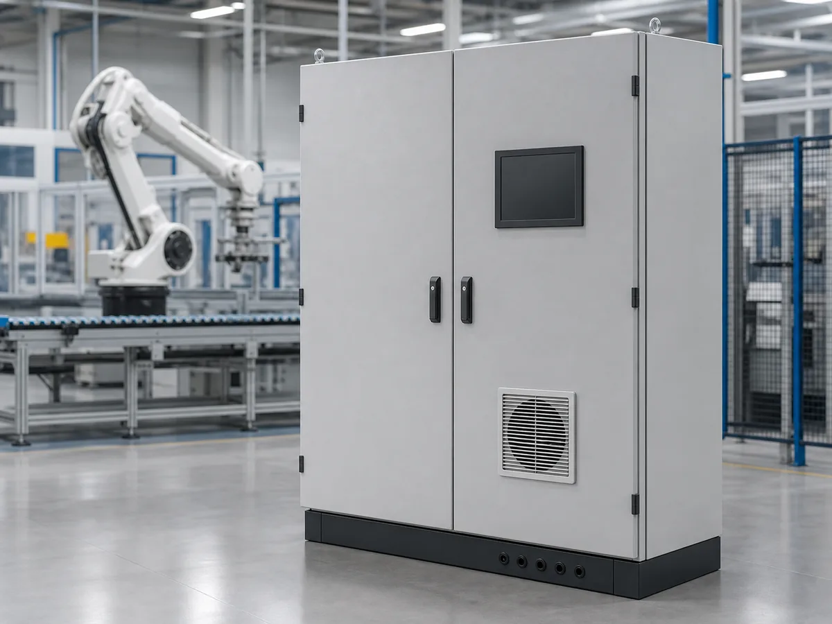
Plan the mounting plate and door
Check device mounts, cable-entry positions and service access before settling the usable cabinet space.
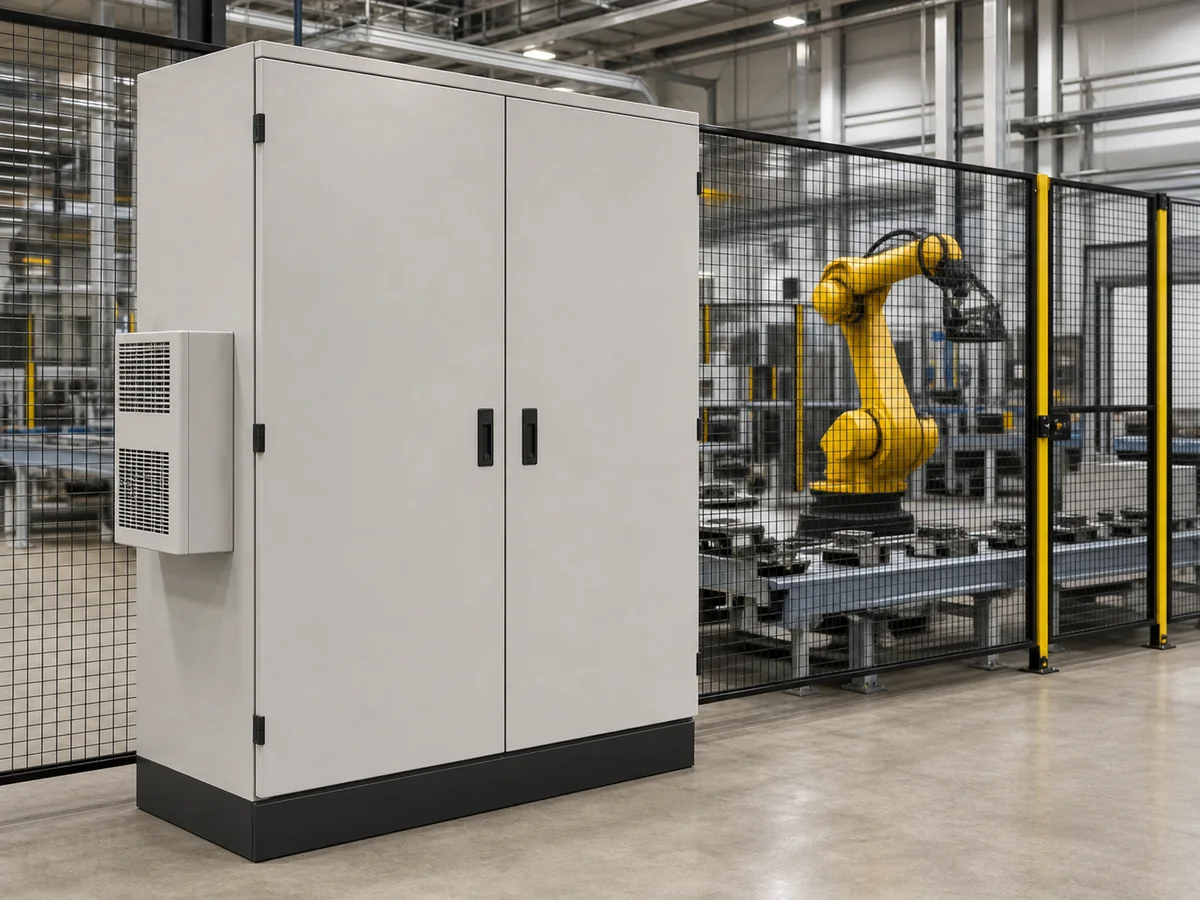
Mounting and access points
Mounting plate
PLC and CPU
Check the mounting method, module width and expansion side.
Remote I/O and relays
Leave room for rails, cable ducts and connector access.
VFD and servo drives
Allow for device weight, spacing, heat loss and cable bends.
Terminals and cable ducts
Keep terminals accessible and power/control routes separate.
Door
HMI opening
Use the exact cutout, fixing pattern and rear depth.
Buttons and indicators
Check hole positions, labels, door load and the cable loop.
Mechanical layout reference; not an electrical schematic.
Mechanical features FN can supply
• Cabinet body, doors and mounting plate.
• Cutouts, holes, studs, rails and brackets to approved drawings.
• Mounting provisions for cable-entry and cooling hardware.
• Dimensional checks and records as agreed.
Choose the enclosure for your equipment
Start with the devices and installation. Each application has different mounting, heat and access requirements.
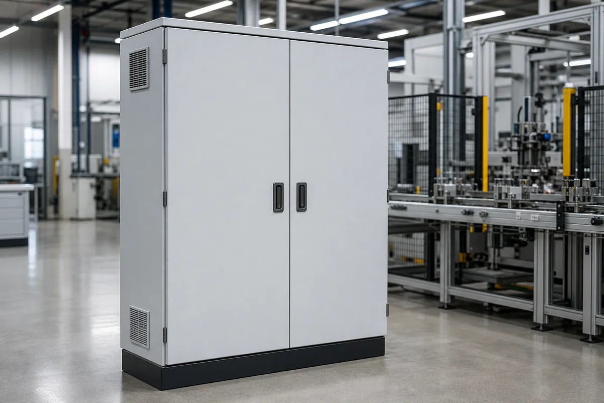
PLC and I/O cabinet
For PLC, remote I/O, relays and terminals. Check usable mounting space before choosing the cabinet size.
• Usable mounting-plate area
• Separate power and control cable routes
• Terminal access and planned expansion
• Door swing and service space
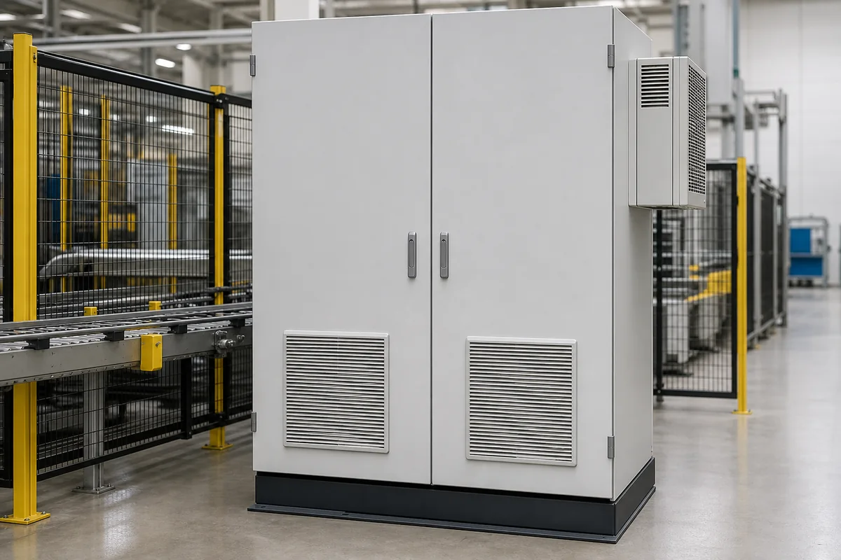
VFD and servo-drive cabinet
Review heat loss and service access before fixing the layout. Compare cooling methods before choosing hardware.
• Device heat-loss data
• Cooling openings and mounting points
• Support for heavy devices
• Power-cable bends and drive removal
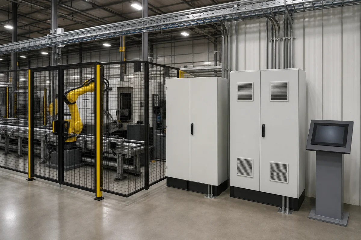
HMI and operator enclosure
For HMIs on a machine, wall or stand, use the exact device drawing. Review cutouts and mounting interfaces, including connector clearance behind the panel.
• Exact cutout drawing and tolerances
• Rear depth and connector clearance
• Operator orientation and door load
• Arm, pedestal or machine mounting
Resolve these conflicts before fabrication
A missing cutout or mounting dimension can mean reworking the door, plate or body. Resolve the points below while the drawings can still change.
The HMI cutout uses a nominal size
The opening may need rework or a replacement door.
Check the cutout, studs, rear depth and reinforcement.
Use the exact device drawing and fixing pattern.
Drive heat loss is missing
A later cooling change can disrupt the layout.
Review cabinet space, cooling interfaces and device spacing.
Provide heat-loss data, ambient conditions and the cooling concept.
Cable routes are decided too late
Power and control cables may cross or crowd the terminals.
Confirm entry zones, gland plates and any barriers.
Provide the cable schedule and separation plan.
The mounting layout omits components
Added devices may collide or require a new mounting plate.
Check usable area, rail positions and plate load.
Update the BOM and layout before drawing approval.
Door load and rear depth are assumed
The door may sag or devices may obstruct its movement.
Review hinges, reinforcement and cabinet depth.
Provide device weights and rear projections.
Service access is checked too late
Filters or devices may be difficult to replace.
Check door direction and removable panels.
Show the machine envelope and available access sides.
Drawings needed to approve the interfaces
Use the current component drawings. Mark unselected parts or cutouts as provisional until the fabrication drawing is approved.
PLC and I/O
Show module sizes, mounting positions and duct gaps.
Confirm the I/O count and planned expansion.
Provide the BOM and rail/duct layout.
HMI and controls
Show the opening, fixings, rear depth and connector space.
Confirm the exact device model.
Provide the DXF or PDF and approved front view.
VFD
Record mounting, weight, clearance and cable bends.
Confirm heat losses and the cooling concept.
Provide the datasheet, loss data and interface drawing.
Servo drives
Show module spacing, bus links and connector access.
Confirm all modules, accessories and the removal path.
Provide the drive arrangement and replacement sequence.
Terminals and cable ducts
Show rail length, cable bends and gland positions.
Confirm where field cables enter and separate.
Provide the cable schedule and terminal plan.
Cooling hardware
Show the cutout, load, seal and service side.
Name the party responsible for thermal validation.
Provide the hardware drawing and agreed responsibilities.
Choose a standard, modified or custom body
Compare the required space, door arrangement and mounting interfaces with an existing cabinet size.
Standard enclosure
Use an existing body when its usable space, environmental suitability, mounting and door arrangement meet the requirements.
• Compare available sizes
• Plan the internal mounting and wiring
• Confirm the mounting plate and accessories
Modified standard enclosure
Keep the standard body when it needs defined changes such as cutouts, gland plates, brackets or a different mounting plate.
• Retain the existing cabinet platform
• Define each modified interface
• Approve the modification drawing
Custom enclosure body
Use a custom body when machine space, access, component density or door geometry rules out a standard size.
• Set the required body dimensions
• Review interfaces before production
• Agree first-article checks and tolerances
What to send for a mechanical review
A provisional BOM or sketch is enough to start a review. Agree final dimensions and supply scope before fabrication.
Start with a BOM or equipment layout
Describe the cabinet briefly in the contact form. Email drawings and longer specifications to info@fnenclosure.com with the project name and drawing revision.
Dimensions and installation
Cabinet size, machine space, mounting points, base and lifting provisions.
Component data
Part numbers, dimensions, weights, mounting patterns and service clearances.
Mounting plate and door
Usable area, rails, ducts, cutouts, door load, rear depth and swing.
Heat and cable routes
Heat losses, cooling method, entry direction, cable bends and separation.
Environment
Indoor or outdoor conditions, contaminants, required material and finish.
Order requirements
Quantity, target market, specifications, packing and required date.
01 / Review inputs
Identify missing dimensions, interface conflicts and undecided items.
02 / Agree the design
Confirm the body, cutouts and mounting provisions.
03 / Approve drawings
Confirm the revision, critical dimensions and inspection points.
04 / Release for fabrication
Manufacture to the approved drawings and agreed inspection requirements.
Agree the inspection points before fabrication
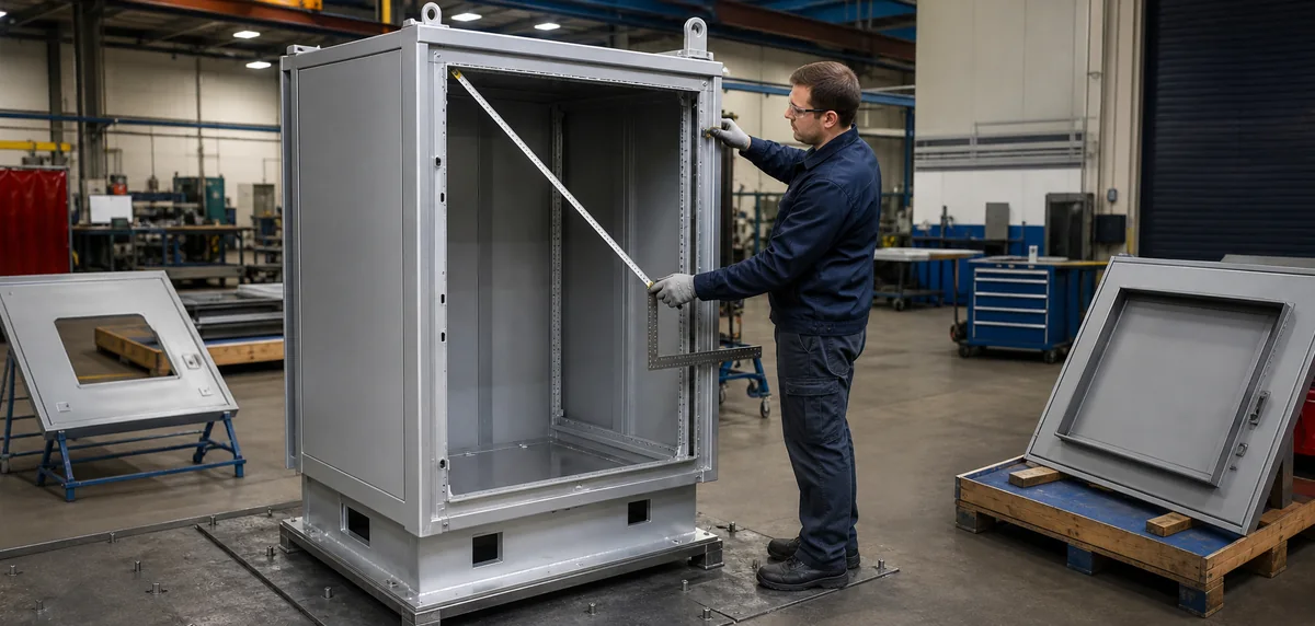
Body squareness and door-frame fit
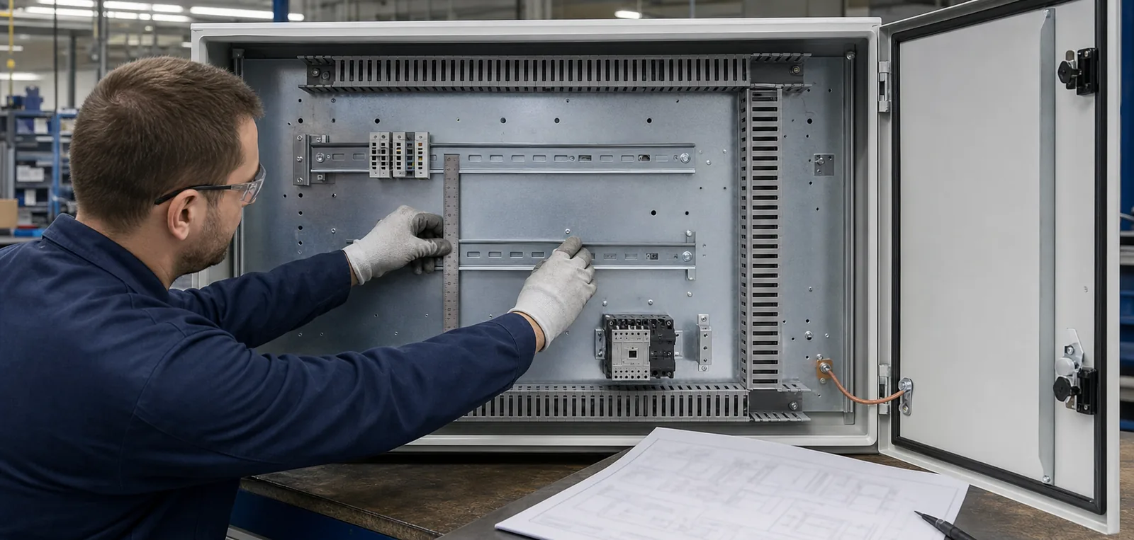
Mounting-plate holes and fixing positions
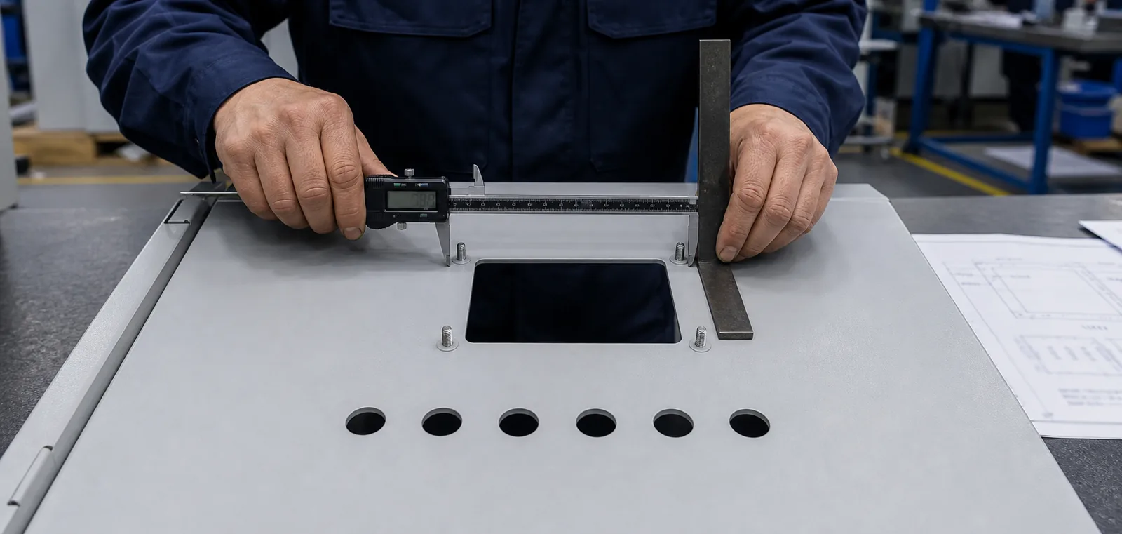
HMI openings and control-hole positions
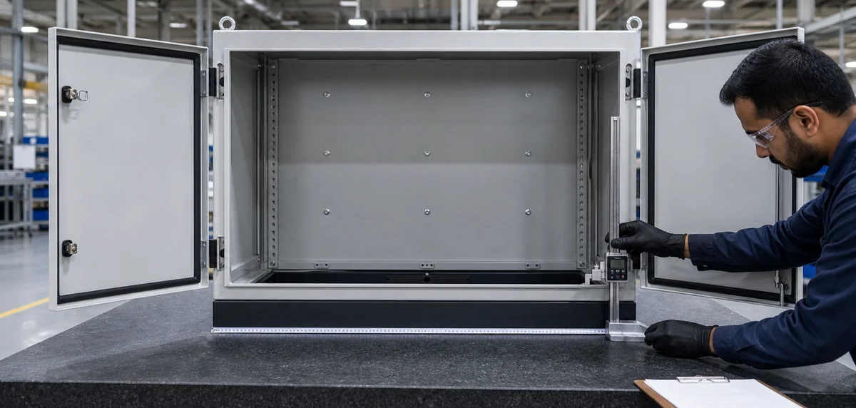
Drawing-linked dimensional checks
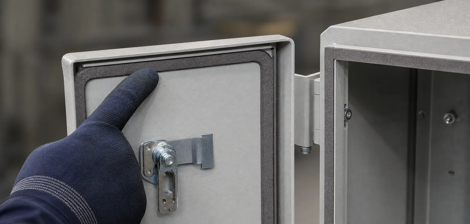
Gasket fit and door closure
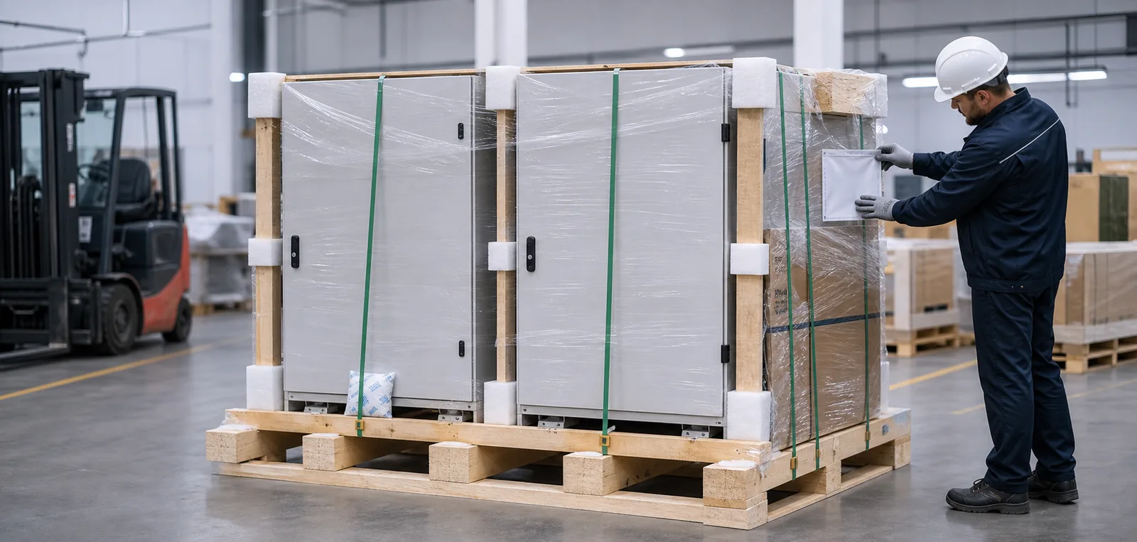
Surface protection and export packing
Define the enclosure and integration responsibilities
Agree who supplies, checks and approves each part of the project before ordering. The enclosure supply covers the specified mechanical work.
FN enclosure supply
Include the required features and records in the quotation.
• Body, doors, mounting plate and specified base or plinth.
• Cutouts, holes, studs, rails and brackets to approved drawings.
• Mechanical provisions for cable-entry and cooling equipment.
• Agreed material, finish and hardware.
• Dimensional or visual records linked to the drawing revision.
Integrator or equipment manufacturer
The responsible system party handles electrical integration and validation.
• Electrical design, component selection, wiring and grounding.
• Programming, networks, control logic and functional safety.
• Cooling selection and final thermal validation.
• EMC, field installation and commissioning.
• Final assembled protection rating and system certification.
First discussion and drawing approval
For a first discussion, share what you have. Before drawing approval, complete the component, cutout and installation details below.
Before drawing approval
• Final BOM with part numbers, dimensions, weights and datasheets.
• Cabinet dimensions, machine space and installation limits.
• Mounting layout for devices, rails, ducts and terminals.
• Approved HMI, control, cooling and cable-entry cutout files.
• Ambient conditions, heat-loss data and cooling concept.
• Cable-entry direction, bend space and route separation.
• Mounting, lifting, door swing and maintenance access.
• Installation environment, material and finish.
• Supply scope, quantity, target market, packing and required date.
• Customer specifications, critical dimensions and inspection records.
For the first discussion
• A provisional BOM or component dimensions.
• A preliminary layout or sketch, if available.
• Application, installation environment and expected quantity.
• Mark undecided items as provisional.
Industrial automation enclosure FAQ
Answers on preliminary files, cutouts, cooling and the scope of supply.
Does the enclosure supply include wiring and PLC programming?
No. The scope described here is the enclosure and agreed mechanical features. Electrical design, wiring, programming and commissioning remain with the integrator or equipment manufacturer.
Can we start before the BOM is complete?
Yes. Send the preliminary list or layout and identify what is still undecided. Resolve the missing dimensions and scope details before requesting a fabrication-ready quotation and approving the drawings.
Can FN make HMI, pushbutton and indicator openings?
Yes, to approved drawings. Specify the device model, opening dimensions, corner radii, fixing pattern and orientation. Include rear depth and connector clearance so the door layout can be checked.
Should a VFD enclosure always use filter fans?
No. Review heat loss, ambient conditions and the cooling concept first. The responsible system designer selects and validates the thermal solution; its hardware determines the required enclosure interfaces.
What if a component changes after drawing approval?
- Submit the revised model and drawing for review before fabrication proceeds. Check the affected openings, mounting points, depth, heat input and cable routes, then confirm the updated drawing revision.
Can cable entries and gland plates be customized?
Yes. Bottom or side entries, removable gland plates, conduit openings and gland locations can be reviewed against the installation conditions and approved drawings.
Does the empty enclosure establish the completed cabinet's IP or NEMA rating?
- No. Openings, accessories, gaskets, assembly and later modifications affect the finished configuration. The responsible system party must verify the required protection for the completed cabinet.
DISCUSS YOUR ENCLOSURE
Start with your component list or layout
Tell us the application, available space and quantity. Mark any preliminary files as provisional. Email drawings to info@fnenclosure.com; use the contact form for a brief project description.