
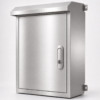
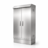
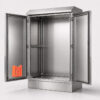
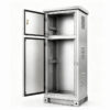
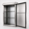
CONFIRMED OEM CAPABILITY
Custom Stainless Steel Enclosures Built to the Drawing
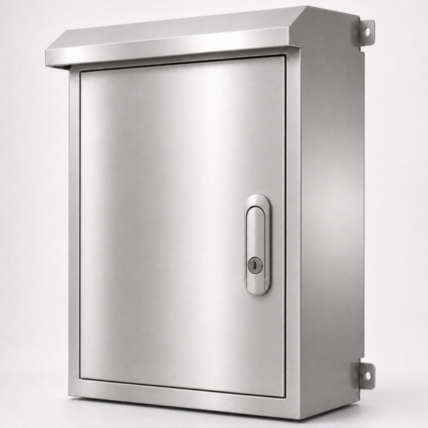
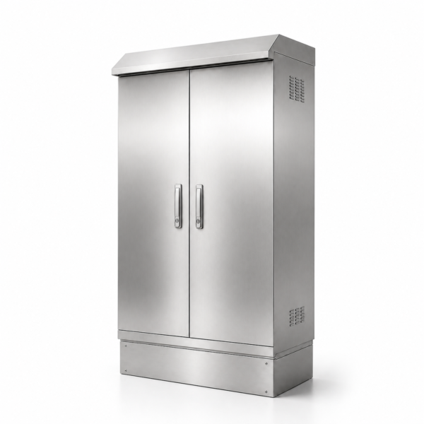
The approved drawing is the manufacturing reference. It controls the product form, dimensions, material, interfaces and acceptance points.
Unusual dimensions are reviewed for structure, door operation, lifting and transport.
Grade selection follows the exposure, cleaning method and drawing requirements.
Body, door and mounting-plate thickness remain drawing-specific.
Hole size, edge distance, torque and anti-rotation requirements are checked together.
Recommended 320–400 grain; grain direction and acceptance sample can be specified.
Installation conditions guide the material, structure, sealing and verification plan.
Best fit
- OEM equipment needs a repeatable enclosure built around its own interfaces.
- Humidity, rain, salt, chlorides, chemicals or washdown affect material selection.
- Cutouts, mounting, door hardware, sealing and visible finish must follow a drawing.
Not the default scope
- An immediate off-the-shelf catalog enclosure with a fixed stock code.
- Electrical and system work is quoted separately.
- A project defined only by a protection label, without installation details, openings, cable entries or a clear test plan.
TECHNICAL DATA
Confirmed Stainless Steel Enclosure Specifications
These values describe FN's confirmed OEM manufacturing range. The approved drawing and quotation still control the exact combination used on each order.
Manufacturing capability
| Specification area | Confirmed capability | Project condition |
|---|---|---|
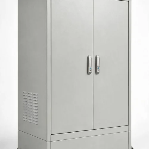
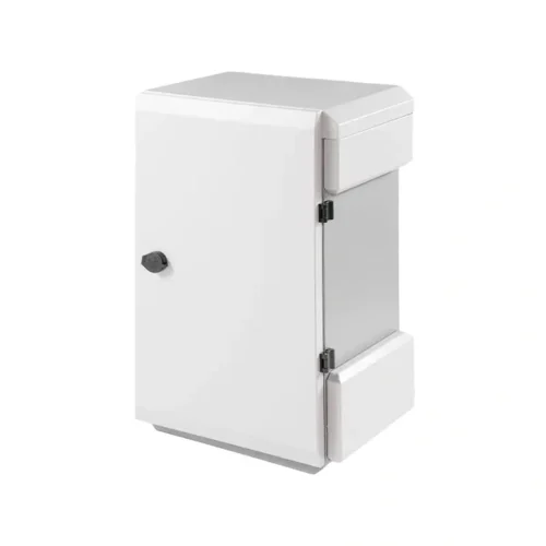
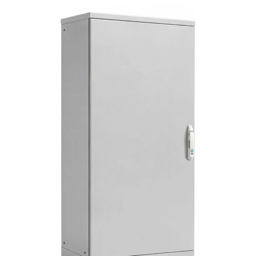
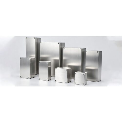
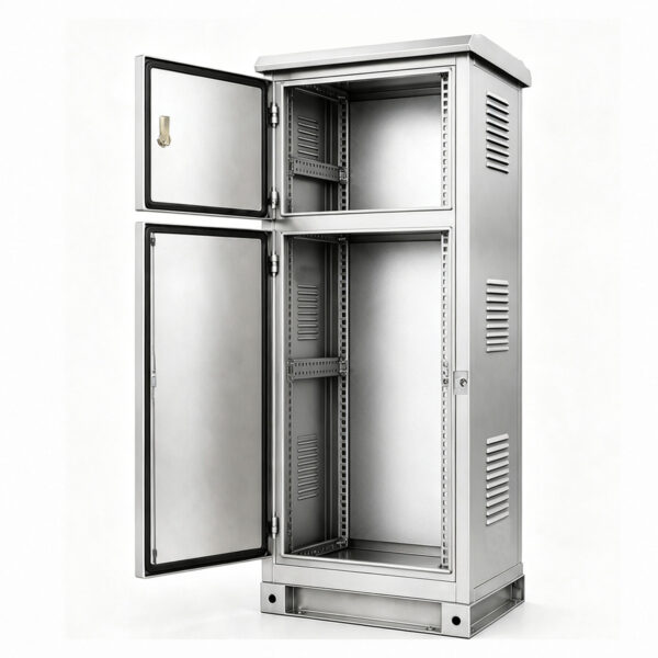
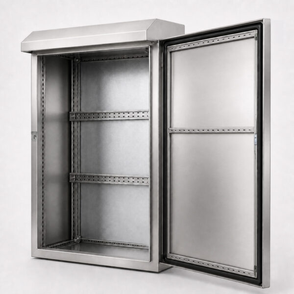
| Forms and dimensions | Wall-mounted enclosures, floor-standing enclosures and junction boxes built to drawing; no fixed catalog minimum or maximum. | Unusual sizes are reviewed for equipment travel, rigidity, door sag, lifting, transport and packing. |
| Materials and thickness | SS304/304L and SS316/316L. Floor-standing body, door and mounting-plate sheet thickness can be specified up to 2.5 mm. | Exact thickness follows size, load, cutouts, reinforcement, flatness and weld-distortion risk. |
| Surface finish | Visible surfaces: No.4 or Scotch-Brite, recommended 320–400 grain. Concealed surfaces: 2B or drawing-defined. Polishing and passivation are available when specified. | Grain direction, visible faces, protection film and acceptance sample are agreed before production. |
| Cutting, forming and welding | Laser cutting, CNC punching, CNC press-brake forming, TIG/MIG welding, stud welding, press-riveting, grinding, brushing, polishing and mechanical assembly. | The route follows the drawing; equipment brands, models and machine precision are not public specifications. |
| Fastening and sealing | Maximum bolt size M20. Continuous welding is used on sealing paths; polyurethane foam-in-place gasket is available, with silicone optional for specified environments. | Thread, plate thickness, edge distance, torque, gasket material and compression path are confirmed during DFM. |
| Dimensional control | Unspecified linear dimensions: ISO 2768-1 class m. Cutout ±0.2 mm; hole position ±0.3 mm; stud or mounting feature ±0.5 mm. | Customer drawing tolerances take precedence; tighter interfaces require feasibility review. |
| Enclosure geometry | Overall dimension ±1.0 mm up to 1000 mm and ±1.5 mm above 1000 mm; door gap 1.5–2.5 mm with variation ≤1.0 mm; diagonal difference ≤2.0 mm/1000 mm; flatness ≤1.5 mm/1000 mm. | Targets apply unless the approved drawing defines another acceptance rule. |
| Protection level and verification | Defined by your project requirements. | State the target protection level, indoor or outdoor location, water and dust exposure, corrosion risks, cable entries, door use and the required test or acceptance method. |
Items defined on the drawing or BOM
| Design item | Required definition |
|---|---|
| Door and access | Door count, hinge side, opening direction, lock points, removable-door requirements and door-mounted load. |
| Mounting and support | Wall brackets, base, feet, lifting points, mounting plate, DIN rails, studs, shelves and reinforcement. |
| Cable and component entry | Gland plates, conduit, connectors, fans, filters, HMI, meters, windows and buttons. |
| Hardware and grounding | Locks, handles, hinges, bolts up to M20, grounding studs, door bonding and loose mechanical parts. |
| Finish and marking | Visible-face direction, brushed grain, weld cleanup, passivation requirement, labels and drawing-defined marking. |
| Supply boundary | Customer-supplied parts, mechanical fitting, optional accessories and any work outside the enclosure body. |
Four checks before drawing release
Size and structure
Check forming capacity, stiffness, door sag, lifting points, handling and transport for unusual dimensions.
Cutouts versus bends
Check edge distance, tool access, component clearance and sealing around every opening.
Door and gasket contact
Confirm the gasket route, corner joints, compression area, hinge position and lock engagement.
Welds and visible faces
Mark visible surfaces and define weld cleanup, grain direction, scratch limits and handling protection.
MANUFACTURING & QUALITY
Controlled Production from Drawing Release to Packing
The drawing revision, inspection points and supply boundary are locked before batch release. Changes are recorded against the affected revision and batch.
Six release gates
- Requirement reviewReceive the drawing, quantity, environment, stainless grade, finish, destination and required evidence.
- DFM and boundary reviewCheck size, bends, openings, M20-or-smaller fastening, hardware, gasket contact, visible faces, customer parts and packing risks.
- Drawing approvalFreeze the production revision, material, thickness, finish, interfaces, documents and responsibilities.
- First articleComplete 100% dimensional and functional inspection when a first article is required; obtain approval before batch production.
- Controlled batchRun first-off, in-process and final inspection. Any temporary change requires impact review and written approval.
- Final inspection and packingRelease the agreed inspection report, packing photos and labels, then pack to the written transport plan.
Inspection and release controls
Critical interfaces — 100%
Cutouts, mounting features, door operation, lock engagement, gasket continuity, grounding points and visible appearance.
First article — 100%
Dimensions and functional checks are recorded before release when a first article is part of the order.
General dimensions
Normal inspection, general level II and recommended AQL 1.0 can be used under ISO 2859-1 unless the customer specifies another rule.
Surface acceptance
Visible finish can use an approved sample and grain direction. Ra ≤0.8 μm is available when the measuring method and positions are agreed.
Documents and export packing
| Area | Available scope | Condition |
|---|---|---|
| Standard records | Approved production drawing, final inspection report and packing photos. | Exact document list is written into the quotation or order. |
| First article and material files | First-article report for first order or design change; material documents when requested. | Format, language and traceability requirement are agreed before production. |
| Project verification | Inspection, special checks or third-party testing can be reviewed for the project. | If a report or test is needed, define the sample, method, responsibility and acceptance criteria before quotation. |
| Inner protection | Visible-surface film, PE inner bag, foam, edge/corner protection, desiccant for sea freight and labelled loose accessories. | Selected by finish, humidity, transit and handling risk. |
| Outer packaging | Carton or pallet for normal products; export plywood case for large or heavy products; ISPM 15 when solid wood is used. | Weight, lifting, stacking and destination requirements are confirmed at quotation. |
QUOTE-READY INPUT
What to Send for a Stainless Steel Enclosure Quote
A useful RFQ identifies the drawing, environment and supply boundary. Missing details can be marked for DFM review rather than guessed.
Supply boundary
| Area | Quote may include | Not included by default |
|---|---|---|
| Enclosure body | Body, door, mounting plate, gasket, hinges, locks/latches, ground studs and drawing-defined sheet-metal parts. | Any feature not shown on the approved drawing or BOM. |
| Mechanical preparation | Cutouts, pressed or welded hardware, DIN rails, gland plates, mechanical accessories, finish and marking. | Unlisted accessories or undefined site modifications. |
| Customer-supplied parts | Incoming check and mechanical fitting after part number, quantity, specification and responsibility are accepted. | Automatic acceptance, substitution or responsibility for missing and damaged parts. |
| Electrical and system work | Only work separately defined and quoted. | Electrical selection, wiring, PLC programming, thermal-system design, complete-system testing and final system approval. |
Eight details for quotation
- Dimensioned drawing and revision, or an annotated sketch.
- Product form, quantity and expected repeat-order pattern.
- Indoor or outdoor exposure, humidity, salt, chemicals and cleaning method.
- Requested stainless grade, sheet-part thicknesses and visible finish.
- Cutouts, cable entries, mounting features and component interfaces.
- Door, hinge, lock, bolt, gasket, grounding and protection requirements.
- Inspection points, documents, tests and customer-supplied parts.
- Destination, packing requirement and target schedule.
For unusual dimensions, send the complete W×H×D combination. FN will review forming, stiffness, door operation, lifting, transport and packing before confirming manufacture.
Stainless Steel Electrical Enclosure FAQs
What triggers an engineering review for an unusual enclosure size?
The review checks forming limits, stiffness, door sag, lifting, handling, transport and packing. Send the complete width, height and depth together with door loads and major cutouts.
What exposure details affect the choice between 304 and 316?
State whether the enclosure faces humidity, rain, salt, chlorides, chemicals or washdown, and describe the cleaning method. These conditions are reviewed together with the drawing and finish requirements.
How should visible brushed stainless surfaces be defined?
Mark the visible faces and grain direction on the drawing. No.4 or Scotch-Brite with a recommended 320–400 grain can be agreed together with protection film and an acceptance sample.
Can custom cutouts and mounting parts be completed before shipment?
Yes, when they are defined on the approved drawing. Position, edge distance, tool access, treatment, clearance and sealing impact are reviewed before release.
How is a required protection level handled?
Provide the target level and working conditions so the structure, sealing paths and cable entries can be reviewed. If a report or third-party test is required, define the sample, method, responsibility and acceptance criteria before quotation.
What should the approved drawing and BOM define?
Define dimensions, material, thickness, cutouts, mounting features, doors, hardware, gasket paths, grounding, visible finish, customer-supplied parts and the supply boundary. The approved revision controls production.
What does first-article inspection cover?
When required, the first article receives 100% dimensional and functional inspection against the approved drawing, including critical interfaces, door operation, gasket contact, visible finish and grounding points.
How are visible stainless surfaces protected for export?
Options include protective film, PE inner bags, foam and corner protection, sea-freight desiccant, labelled loose accessories, pallets or export plywood cases. The final method follows the finish, size, weight and destination.