
Power Distribution Enclosure Bodies for Panel Builders
FN makes the enclosure body around panel-builder-approved device, busbar-support, compartment, door, cable and site drawings. The panel builder designs and verifies the complete electrical assembly.
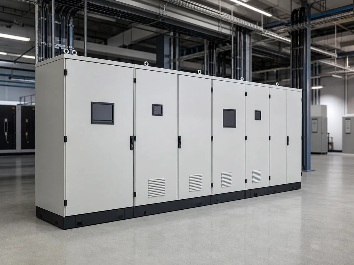
01 / SYSTEM POSITION
A mechanical body for the panel builder's design
The body provides approved mounting points and space for devices, busbar supports, terminals, partitions and doors, plus the required cable-entry and site-mounting features.
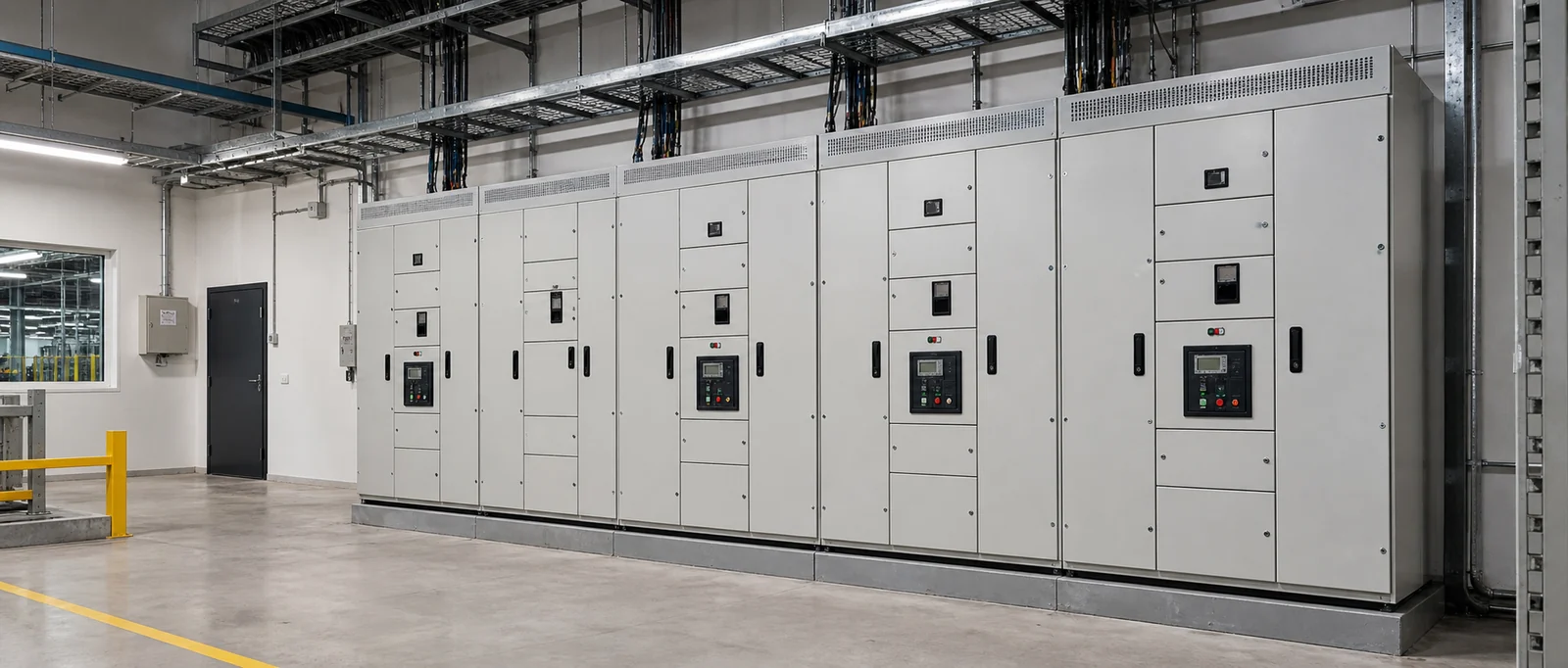
Power Distribution Mechanical Platform Map
POWER + DEVICE ZONES
Incoming Device Zone
Device envelope, mounting, door access and conductor approach.
Busbar / Conductor Zone
Support coordinates, panel-builder clearances and access.
Feeder / Protective Devices
Mounting area, compartment, handle or door-interface provisions.
Cable Terminal Zone
Entry, bend radius, glanding, termination space and removable plates.
STRUCTURE + ACCESS
Partitions + Doors
Compartment walls, hinges, latches, interlock provisions and service sequence.
Base + Installation
Plinth, anchors, lifting, lineup connection and site access.
Mechanical platform diagram · not a complete switchboard, switchgear or electrical verification package
FN manufacturing scope
- Cabinet body, doors, mounting plates, partitions, supports, base/plinth and defined structure.
- Approved holes, cutouts, handle or interlock provisions and cable-entry plates.
- Mechanical provisions for busbar supports or equipment mounting from panel-builder drawings.
- Agreed dimensional, visual, hardware and packing records.
Boundary: Electrical design, device and busbar selection, required clearances, short-circuit or temperature performance, wiring, protection coordination, interlock function, testing, commissioning and complete-assembly certification remain with the responsible panel builder or system manufacturer.
02 / TYPICAL CONFIGURATIONS
Three Distribution Enclosure Routes With Different Mechanical Complexity
Small boxes, floor-standing distribution cabinets and modular lineups require different device, conductor, compartment and installation reviews.
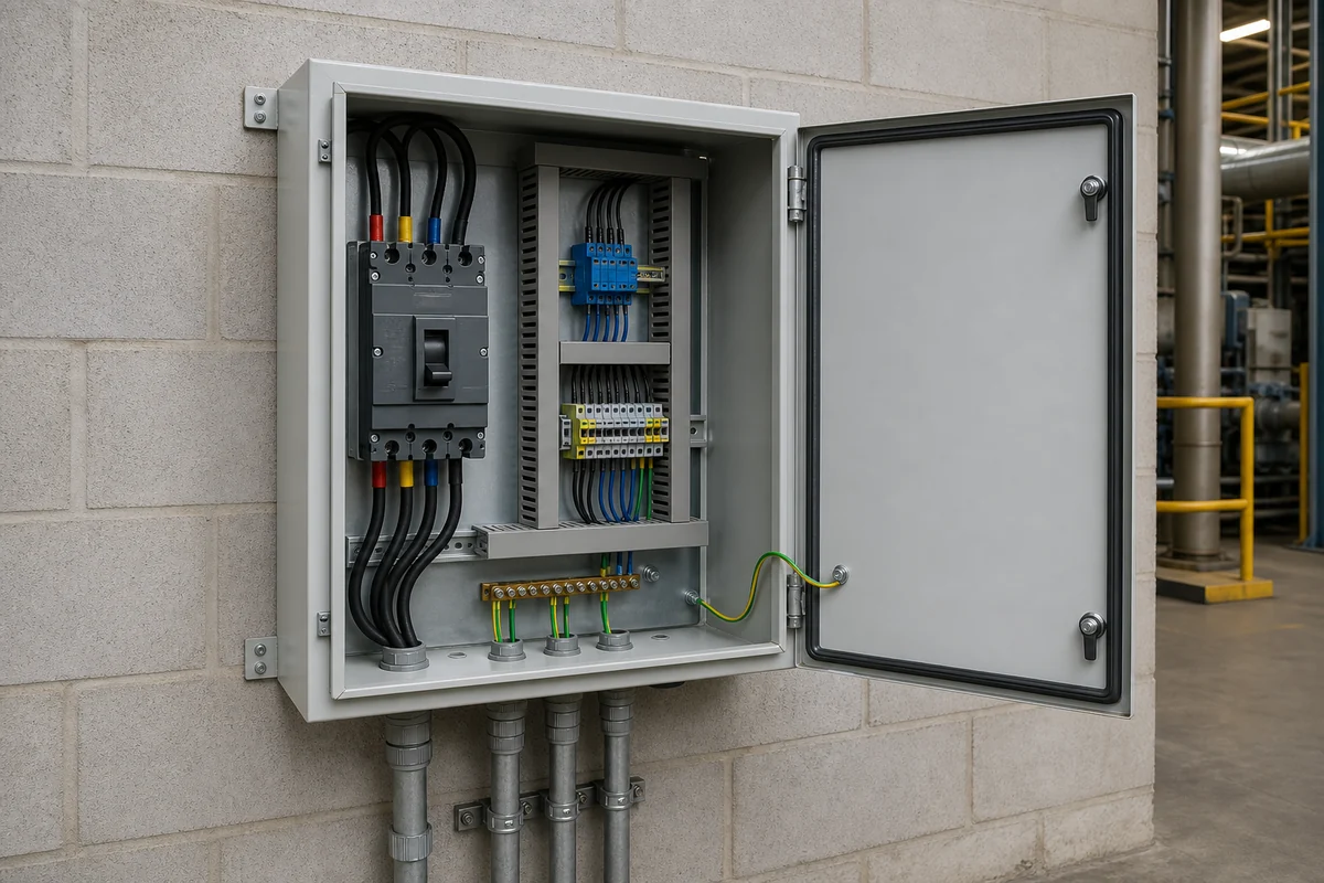
Small Distribution / Tap Enclosure Body
Wall- or equipment-mounted bodies for compact devices, terminals or conductors.
- Device and conductor envelope
- Conduit or cable entry pattern
- Door or cover access
- Mounting and field-connection space
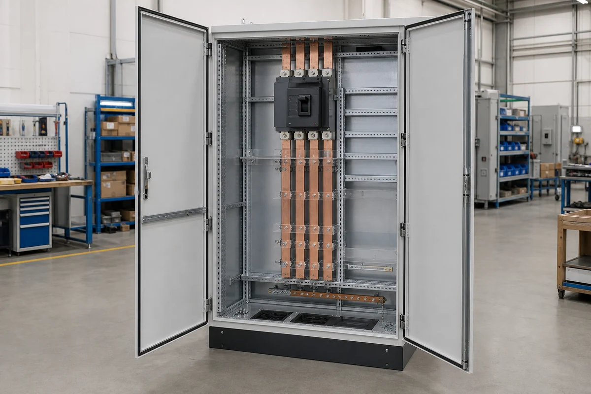
Floor-Standing Distribution Cabinet
Single-bay cabinets for larger incoming, feeder and terminal arrangements.
- Device and busbar layout
- Door and handle interface
- Cable bend and termination zones
- Base, lifting and service access
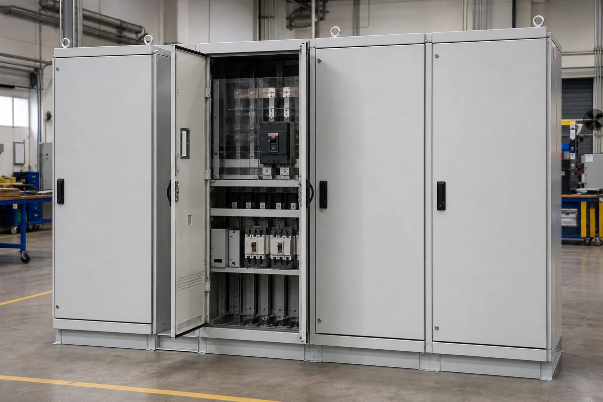
Multi-Bay / Compartmented Lineup Body
Project-specific mechanical platforms for modular or segregated assemblies.
- Lineup and compartment plan
- Busbar/support coordinates
- Door/interlock provisions
- Site joining, base and variant control
03 / FAILURE MODES
Mechanical Assumptions That Disrupt Panel-Builder Verification
The enclosure should be released from the panel builder’s actual layout and specification, not from a generic power distribution cabinet description.
Busbar layout or clearance assumptions are missing
Consequence: Supports, partitions or body depth require redesign.
Mechanical decision: Internal geometry, support coordinates and access.
Required input: Panel-builder busbar layout and required clearance assumptions.
Door handle or interlock provisions are selected late
Consequence: Door cutouts, rods, brackets or device alignment change.
Mechanical decision: Door stiffening, hardware pattern and internal clearance.
Required input: Exact hardware or device model and interface drawing.
Cable termination space is underestimated
Consequence: Conductors cannot bend or terminate as planned.
Mechanical decision: Bottom or top zones, gland plates, depth and removable panels.
Required input: Cable or conductor schedule, entry direction and bend requirements.
Compartment boundaries are provisional
Consequence: Partitions, doors and equipment access conflict.
Mechanical decision: Barrier geometry, fastening, door sequence and service path.
Required input: Approved compartment plan and functional responsibility.
Heat or ventilation assumptions arrive after layout
Consequence: Openings, volume or equipment spacing change late.
Mechanical decision: Ventilation or cooling provisions and usable space.
Required input: Loss data, ambient and responsible party’s thermal concept.
Customer specification revision is not controlled
Consequence: Mechanical features or records are missed across batches.
Mechanical decision: Material, hardware, CTQs, labels and documentation.
Required input: Approved specification, deviation list and revision matrix.
04 / DESIGN REVIEW MATRIX
Device, Busbar, Compartment, Door and Cable Interface Matrix
FN translates panel-builder-approved electrical-layout assumptions into a manufacturable mechanical platform.
Devices
Interface: Envelope, weight, mounting, handle position and service clearance.
Review question: Are exact incoming and feeder device models approved?
Release evidence: Device schedule + coordinates + manufacturer drawings.
Busbar / Conductors
Interface: Support positions, route, joints, access and specified clearances.
Review question: Which dimensions are mandatory for assembly verification?
Release evidence: Busbar layout + support drawing + responsibility note.
Compartments
Interface: Partitions, access, removable covers and fastening.
Review question: Which zones must be separated mechanically?
Release evidence: Approved compartment plan + service sequence.
Doors / Interlocks
Interface: Cutouts, handles, rods, brackets, hinges and opening sequence.
Review question: Which hardware and functional party control the interface?
Release evidence: Hardware drawing + door elevation + responsibility matrix.
Cable Termination
Interface: Entry, conduit or glands, bend radius, lugs and field access.
Review question: What conductor sizes and approach directions apply?
Release evidence: Cable or conductor schedule + terminal-zone drawing.
Base / Lineup / Site
Interface: Plinth, anchors, lifting, joining holes, floor trench and service aisle.
Review question: How will cabinets be installed, joined and maintained?
Release evidence: Site GA + base/lineup drawing + handling plan.
05 / CONFIGURATION ROUTES
Choose the Mechanical Platform From Assembly Complexity
Use the simplest body that still preserves the panel builder’s approved device, conductor, compartment and service interfaces.
Standard Box / Cabinet
Use when catalog geometry and accessories meet device, cable, mounting and environment needs without structural changes.
- Fast comparison route
- Panel builder controls internal adaptation
- Confirm usable space and entry zones
Modified Distribution Cabinet
Use when a known body needs project doors, plates, cutouts, supports, gland plates or base features.
- Controlled project modifications
- Retains a known platform
- Approved interface drawings required
Fully Custom / Modular Body
Use for unusual device arrangements, conductors, compartments, lineups, doors or site installation.
- Project-specific mechanical platform
- Full interface and specification review
- First-article CTQs and variant control
06 / BEFORE QUOTATION
What to confirm for a distribution enclosure quote
Quote the enclosure body separately from the panel builder’s electrical design, assembly, testing and certification.
Start with the approved device and busbar layout
FN reviews device, busbar, compartment, door, cable and site information to define body geometry, supports, openings, hardware provisions, CTQs and commercial assumptions.
Devices & Layout
Exact models, dimensions, weights, mounting, handles and service access.
Busbar / Conductors
Routes, support coordinates, joints, required clearances and panel-builder responsibility.
Compartments & Doors
Partitions, door sequence, locks, interlock provisions, removable panels and labels.
Cable & Terminals
Incoming or outgoing direction, conductor size, bend space, glands or conduit and field access.
Base, Lineup & Environment
Plinth, anchors, lifting, joining, floor or trench interface, material and finish.
Specification & Commercial
Customer specification, deviations, quantity, variants, CTQs, packing and date.
Gate 01 · Layout Input Review
Confirm devices, conductors, compartments, doors and cable zones.
Gate 02 · Mechanical Proposal
Align body, supports, plates, openings, hardware provisions and base.
Gate 03 · Panel-Builder Approval
Freeze drawings, responsibility notes, CTQs and specification revision.
Gate 04 · Fabrication Release
Manufacture and inspect against the approved mechanical package.
Mechanical Details to Review
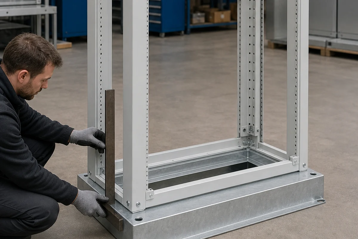
Cabinet Frame + Base
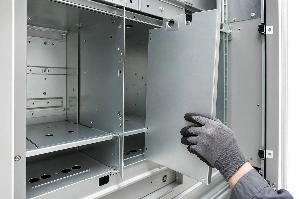
Partition + Compartment Detail
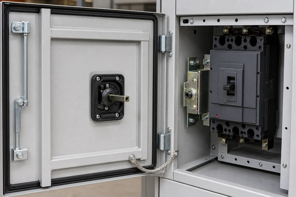
Door / Handle Interface Check
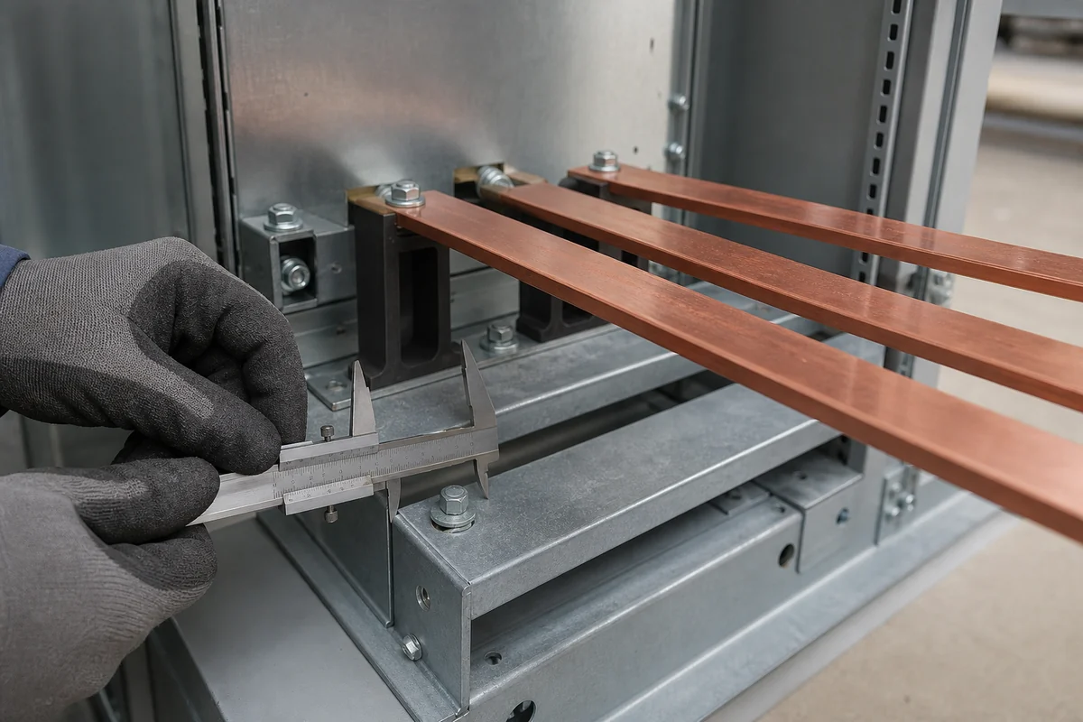
Support / Mounting Pattern
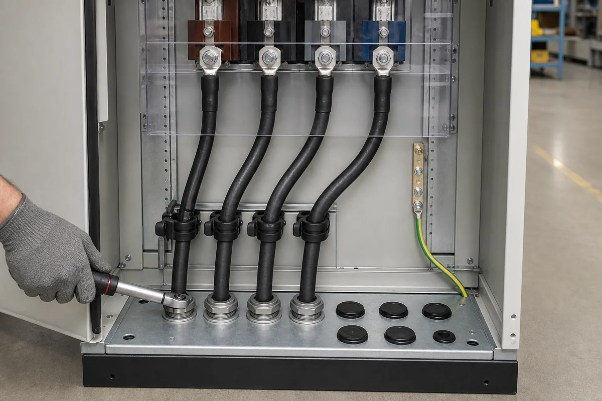
Cable Entry + Terminal Zone
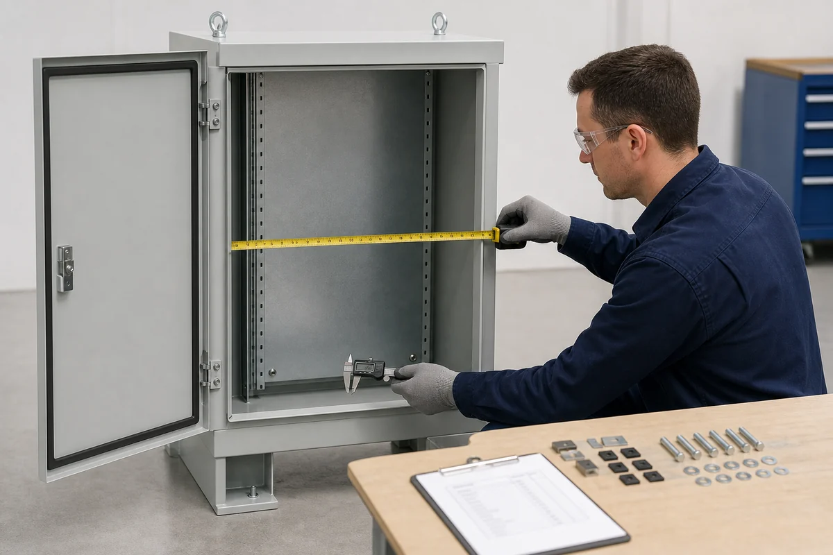
First-Article Checks to Specify
Enclosure Mechanical Platform vs. Complete Distribution Assembly
FN prepares the body for panel-builder verification; FN does not imply responsibility for the complete electrical assembly.
FN Enclosure Manufacturing Scope
FN enclosure manufacturing scope:
- Cabinet body, frame, doors, mounting plates, partitions, base/plinth and approved hardware.
- Approved holes, cutouts, supports, brackets, gland plates and mechanical interfaces.
- Material and finish within the released specification.
- Lineup, anchor or site-interface features defined in the approved drawings.
- Drawing-linked dimensional, visual, hardware and packing records as agreed.
Panel Builder / Equipment Manufacturer Scope
Panel Builder / Equipment Manufacturer Scope:
- Electrical architecture, device selection, busbar or conductor design and required clearances.
- Protection coordination, wiring, grounding and functional interlocks.
- Temperature-rise, short-circuit and other complete-assembly verification.
- Installation, field connections, commissioning and maintenance instructions.
- Final product marking, certification and regulatory compliance.
Start with the panel-builder layout package
Use one drawing revision for the device schedule, busbar supports, door hardware, cable routes and base so the enclosure matches the panel builder’s approved design.
Project Information Checklist
- Device schedule — models, dimensions, weights, mounting and handle positions.
- General arrangement — overall envelope, bay arrangement and service sides.
- Busbar / conductor layout — routes, support coordinates and required clearances.
- Compartment plan — partitions, doors, covers and access sequence.
- Door / interlock interfaces — exact hardware, cutouts, rods, brackets and responsibility.
- Cable / terminal plan — entry, conductor sizes, bend space and glanding or conduit.
- Thermal assumptions — losses, ambient, ventilation or cooling concept and validation party.
- Base / site drawing — plinth, anchors, lineup, floor or trench and lifting.
- Customer specification — material, finish, hardware, labels, CTQs and deviations.
- Commercial inputs — quantity, variants, packing, target market and date.
Recommended First Package
- Device and busbar layout
- Compartment and door elevation
- Cable-entry or terminal-zone drawing
- Customer specification and deviations
Power Distribution Enclosure FAQ
Questions specific to panel-builder mechanical platforms, devices, busbars, compartments, doors and cable zones.
Does FN supply a complete switchboard or switchgear assembly?
This page covers enclosure bodies and approved mechanical interfaces. Electrical design, busbars, devices, wiring, protection, testing, commissioning and complete-assembly certification remain with the responsible panel builder or equipment manufacturer unless separately contracted and verified.
What should a panel builder send for quotation?
Send the device schedule, general arrangement, busbar and support layout, compartment plan, door and interlock interfaces, cable and terminal zones, base or site drawing, customer specification, quantity and date.
Can FN manufacture busbar supports or conductor interfaces?
FN can manufacture approved brackets, holes or support provisions from panel-builder drawings. Conductor design, material, clearances, temperature and short-circuit verification remain with the responsible assembly designer.
How are door-mounted handles and interlocks coordinated?
Provide exact device and hardware models, manufacturer interface drawings, door elevation, linkage geometry, opening sequence and the party responsible for functional validation.
Why is cable termination space reviewed before body release?
Conductor size, lug orientation, bend radius, entry direction and field access can change cabinet depth, bottom or top zones, gland plates and removable-panel needs.
Can FN support repeat modular cabinet variants?
Use a released master body, bay or option matrix, variant drawings and revision-controlled CTQs so doors, plates, bases and openings remain traceable.
Does the enclosure body carry complete assembly certification?
Not by itself. Complete assembly performance and certification depend on the populated design, components, conductors, wiring, assembly and verification by the responsible manufacturer.
START FROM THE PANEL-BUILDER LAYOUT
Discuss the Device, Busbar, Door and Cable Layout
Describe the cabinet in the contact form. Email the panel-builder drawings to info@fnenclosure.com with the project name and revision; we will review missing mechanical interfaces.