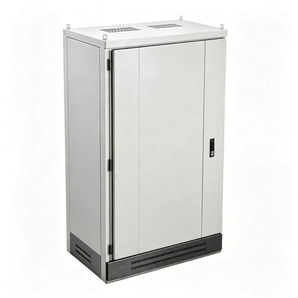
DRAWING-BASED OEM PROJECT
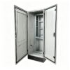
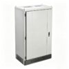
Modular Electrical Enclosures for module datums, baying alignment and panel interchange
A modular enclosure project succeeds when frames, bays, panels and cable routes repeat from one module to the next.
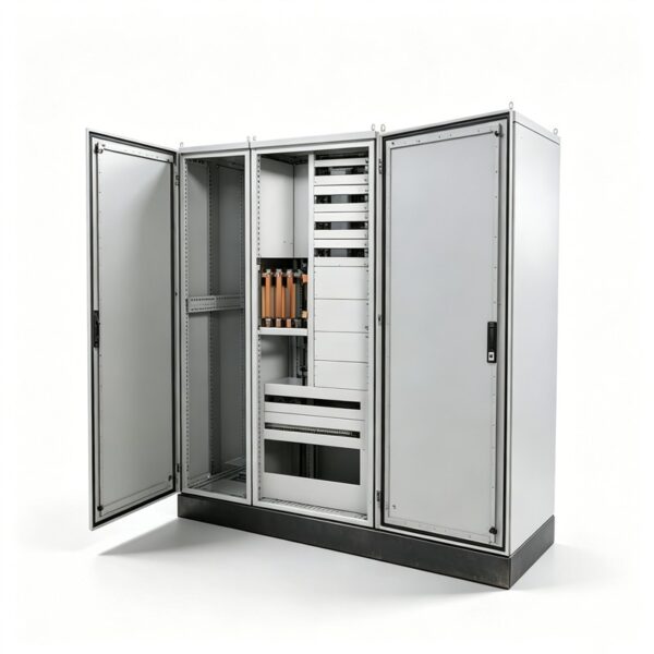
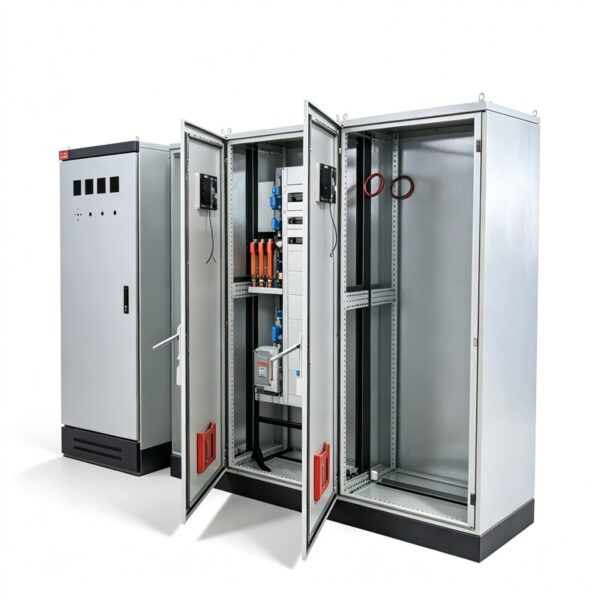
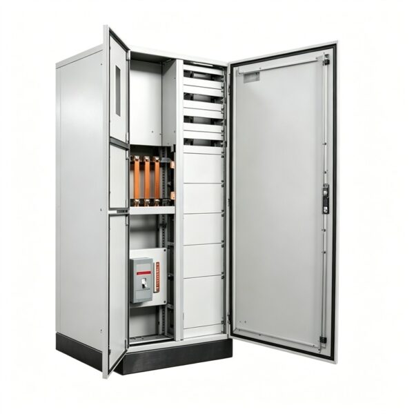
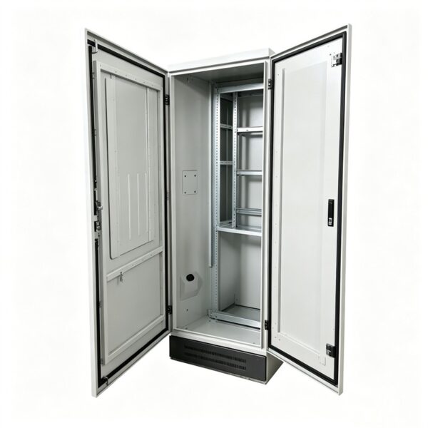
Bay width, cabinet height and depth, frame pitch and repeated datums are set by the lineup drawing.
Review baying points, panels, partitions, plinths, cable routes and the site assembly plan together.
Choose material and finish after reviewing corrosion, visible surfaces, touch-up and component interfaces.
Use the same datums for frames, doors, panels, partitions and bases across the lineup.
Check bay alignment, diagonal, door gaps, panel interchange and interface records.
Separate the mechanical enclosure from busbar, wiring, components and system certification.
Best fit
- A cabinet line needs repeatable bay dimensions and shared interfaces.
- Equipment sections require partitions, mounting systems and controlled cable routes.
- Transport, site joining or future expansion affects the cabinet architecture.
Not the default scope
- A large welded box described as modular without a repeatable interface.
- Baying holes, doors and panels defined independently after fabrication starts.
- Assuming every module can carry the same equipment or lifting load.
DESIGN INPUTS
Freeze the Module Grid and Baying Interfaces
Common datums must align frames, doors, panels, partitions and bases across the whole lineup.
| Project variable | Decision required |
|---|---|
| Module grid | Bay width, cabinet height/depth, frame pitch and repeated datum system |
| Baying interface | Joining points, side-panel removal, gasket or closure and site access |
| Internal architecture | Mounting plates, rails, partitions, busbar/cable zones and component clearances |
| Doors and panels | Front/rear access, split doors, side panels, roof, base and removable sections |
| Plinth and mounting | Base height, floor fixing, levelling, cable entry and handling points |
| Material and finish | Environment, corrosion, coating, visible surfaces and touch-up expectations |
| Tolerance and inspection | Bay alignment, diagonal, door gaps, panel interchange and interface checks |
| Supply boundary | Mechanical enclosure scope separated from busbar, wiring, components and system certification |
Protect repeatability across cabinet bays
Bay width, cabinet height/depth, frame pitch and repeated datum system
Joining points, side-panel removal, gasket or closure and site access
Mounting plates, rails, partitions, busbar/cable zones and component clearances
Front/rear access, split doors, side panels, roof, base and removable sections
ENGINEERING & QUALITY
Control Datums, Panel Fit and Repeat-Build Interfaces
One drifting frame can disturb adjacent doors, removable panels and joining points across the lineup.
Modular lineup release sequence
- 01Define the module grid and cabinet lineup.Bay dimensions, frame pitch and repeated interface datums are recorded.
- 02Map equipment zones, partitions and cable paths.Equipment zones, loads, partitions and cable paths are mapped.
- 03Set baying, base, roof, panel and door interfaces.Baying points, base, roof, panels and doors are checked together.
- 04Review lifting, transport split and site assembly access.Lifting points, transport splits and site-baying access are reviewed.
- 05Freeze interface dimensions and first-article checks.Material, finish, environment, protection target and first-article checks are agreed.
- 06Control revisions, loose parts, labels and packing by bay.Bay labels, loose parts, revision records and packing are controlled by lineup.
Repeat-build interface checks
Check frame geometry, repeated datums, mounting systems and component clearances.
Check baying holes, panel fit, door alignment and removable sections.
Confirm mounting plates, partitions, cable zones, base fixing and lifting points.
Record bay identification, loose parts, packing and drawing revision.
PROJECT FAQ
Send the Lineup, Module and Transport-Split Inputs
Show what repeats, what changes by bay and what must be joined after delivery.
Modular Electrical Enclosures project data and evidence status
| Field | Buyer-facing value | Status |
|---|---|---|
| Manufacturable size | Bay width, cabinet height/depth, frame pitch and repeated datum system | Project-defined |
| Material and thickness | Carbon steel, galvanized steel, stainless steel, aluminum, or drawing-specified material; exact thickness remains on the drawing. | Conditional scope |
| Surface treatment | State the environment, corrosion exposure, material grade, coating, visible surfaces, and touch-up expectations at quote stage. | Quote input |
| Fabrication route | The route follows joining points, side-panel removal, gasket or closure and site access; fixed equipment specifications are not published. | Scope confirmed later |
| Joining and sealing | Define the baying joints, side-panel interfaces, door and panel closure, gasket details, and sealing method on the approved drawing. | Drawing decision |
| Tolerance and inspection | Frame geometry and repeated datums; acceptance method must be agreed. | Acceptance input |
| Tests and files | The record should cover module datums, baying alignment, panel interchangeability, and the agreed verification scope. No certification is claimed. | Conditional evidence |
| First article and batches | Freeze interface dimensions and first-article checks. | Customer requirement |
| Packaging and destination | Control revisions, loose parts, labels and packing by bay. | Delivery input |
| Project photographs | No approved public modular cabinet customer-photo set is currently available. | Public evidence unavailable |
| Drawing examples | No anonymous modular cabinet drawing case has been cleared for public release. | Public evidence unavailable |
| BOM and assembly boundary | Mechanical enclosure scope separated from busbar, wiring, components and system certification | Must be defined |
| Inquiry description | Describe frame grid, baying interface, doors and panels, mounting plates, partitions, plinths and transport splits; verified family inquiry data has not been published. | Sales confirmation needed |
| Proven applications | Selection contexts are shown, but no approved completed-project list is public for this modular cabinet. | Public evidence unavailable |
Modular Electrical Enclosures buyer questions
What makes an enclosure truly modular?
A repeatable grid and controlled interfaces between frames, panels, doors, bases and internal systems—not simply a large cabinet divided into sections.
Can cabinet dimensions be customized?
Yes as a drawing-based OEM project, but module proportions, stiffness, door behavior, lifting and transport need review before quotation.
How are multiple bays joined?
Define the baying points, access side, closure or gasket requirement, alignment method and whether joining occurs at the factory or site.
Can partitions and mounting systems be included?
They can be quoted when their positions, loads, hole patterns, material and supply condition are defined.
Does FN supply complete switchgear?
The mechanical enclosure scope must be separated from busbar, wiring, electrical components, testing and system certification. Do not assume a full electrical system.
What controls repeat production?
Use common datums, frozen interface dimensions, drawing revisions, controlled hardware, inspection points and bay identification.
What must be planned for transport?
Cabinet split, lifting points, doors/panels shipped fitted or loose, plinth condition, destination and site handling constraints.
Are certifications included?
No current certification is claimed. Any standard, test or third-party document must be specified as a project requirement before quotation.