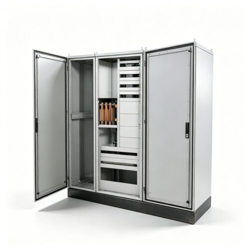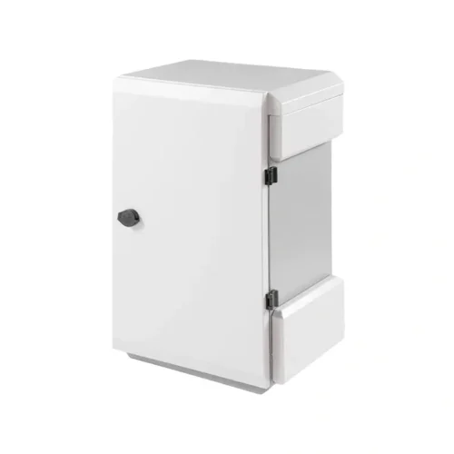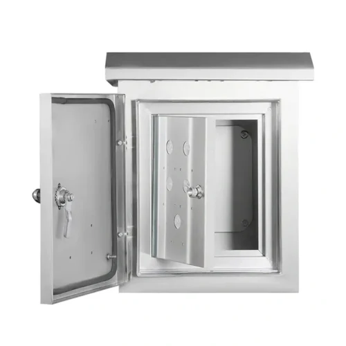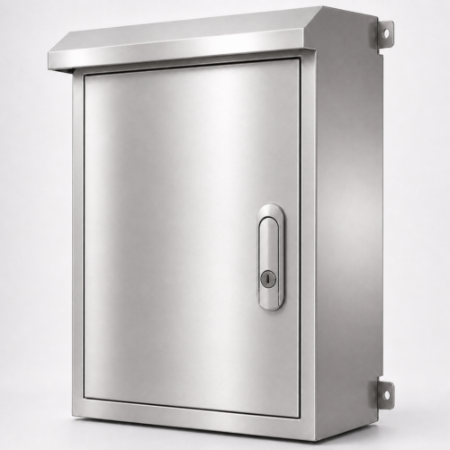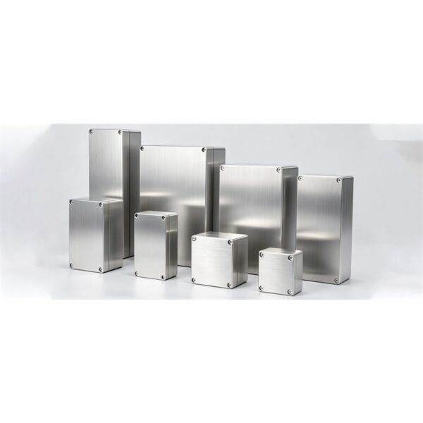
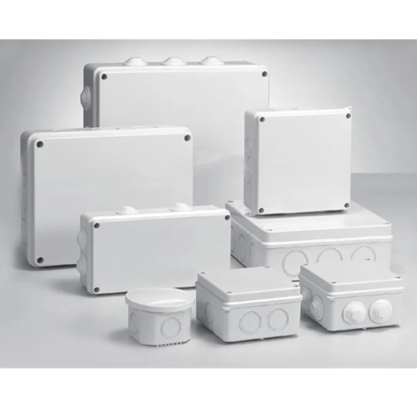
DRAWING-BASED OEM PROJECT
Junction Boxes for entry hardware, terminal clearance and cover closure
A junction box should be designed around cable entry, terminal space and service access—not treated as an empty box with holes added later.
Overall size, usable depth, cover clearance and mounting envelope are set by the drawing.
Review cable entry, terminal space, grounding, cover access and service tools together.
Choose material and finish after reviewing exposure, cleaning, terminals and visible surfaces.
Check cover type, opening direction, fastener access and gasket path against the internal layout.
Agree the entry hardware, terminal clearance, cover closure and required inspection records.
Separate the empty box, fitted hardware, customer parts, BOM items and electrical work.
Best fit
- Field wiring or machine wiring does not fit a standard catalog box.
- Cable entries, terminals and wire-bending space must be coordinated in one drawing.
- The cover, mounting and service direction are defined by the equipment layout.
Not the default scope
- A stock box selected only by outside dimensions.
- Unplanned field drilling through an unspecified sealing boundary.
- Electrical components or wiring included without an agreed BOM and assembly scope.
DESIGN INPUTS
Plan Cable Entry, Terminal Space and Cover Access
Start with the conductor path. A late gland hole can remove terminal clearance, weaken an edge or leave no room to tighten the connector.
| Project variable | Decision required |
|---|---|
| Dimensions | Overall size, usable internal depth, cover clearance and mounting envelope |
| Cable entry | Gland or conduit schedule, connector model, hole size, edge distance and entry direction |
| Internal layout | DIN rail, terminals, mounting plate, grounding points, labels and wire-bending space |
| Cover and access | Screw or hinged cover, opening direction, lock or fastener access and gasket path |
| Material and finish | Exposure, material grade, coating or visible-finish requirement |
| Joining and sealing | Welded seams, press-fasteners, studs and sealing method to be confirmed from the drawing |
| Tolerance and inspection | Critical hole positions, fit checks and acceptance points to be identified before quotation |
| Supply boundary | Empty box, fitted hardware, customer-supplied parts, BOM items and electrical work stated separately |
Check the box from cable to cover
Overall size, usable internal depth, cover clearance and mounting envelope
Gland or conduit schedule, connector model, hole size, edge distance and entry direction
DIN rail, terminals, mounting plate, grounding points, labels and wire-bending space
Screw or hinged cover, opening direction, lock or fastener access and gasket path
ENGINEERING & QUALITY
Inspect Openings, Wiring Space and Cover Fit
Follow the installer from the cable entry through the conductor bend to the terminal and closed cover.
Junction-box release sequence
- 01Review the cable schedule and installation direction.The cable and connector schedule, entry direction and service access are recorded.
- 02Freeze enclosure, cover, mounting and internal layout dimensions.The enclosure, cover, mounting and internal layout dimensions are frozen.
- 03Check cutouts against glands, connectors, terminals and tool access.Cutouts are checked against glands, connectors, terminals and tool access.
- 04Agree material, finish, joining, gasket and hardware scope.Material, finish, joining, gasket and hardware requirements are agreed.
- 05Identify first-article, inspection, photo or document requirements.First-article, inspection, photos and document requirements are recorded.
- 06Confirm packaging, destination and repeat-order revision control.Packaging, destination and repeat-order revision control are confirmed.
Box-specific acceptance points
Check the opening schedule, usable space, DIN rail, terminals and bend clearance.
Check cover fit, gasket path, fastener access and opening direction.
Confirm grounding, internal mounting, fitted parts, material and finish.
Record drawing revision, labels, packing, shipping condition and agreed sealing scope.
PROJECT FAQ
Send the Cable, Terminal and Access Schedule
A cable and terminal sketch is more useful than outside dimensions alone.
Junction Boxes project data and evidence status
| Field | Buyer-facing value | Status |
|---|---|---|
| Manufacturable size | Overall size, usable internal depth, cover clearance and mounting envelope | Project-defined |
| Material and thickness | Carbon steel, galvanized steel, stainless steel, aluminum, or drawing-specified material; exact thickness remains on the drawing. | Conditional scope |
| Surface treatment | Exposure, material grade, coating or visible-finish requirement | Quote input |
| Fabrication route | The route follows gland or conduit schedule, connector model, hole size, edge distance and entry direction; fixed equipment specifications are not published. | Scope confirmed later |
| Joining and sealing | Welded seams, press-fasteners, studs and sealing method to be confirmed from the drawing | Drawing decision |
| Tolerance and inspection | Opening schedule and usable internal space; acceptance method must be agreed. | Acceptance input |
| Tests and files | The record should cover entry hardware, terminal clearance, cover closure, and the agreed verification scope. No certification is claimed. | Conditional evidence |
| First article and batches | Identify first-article, inspection, photo or document requirements. | Customer requirement |
| Packaging and destination | Confirm packaging, destination and repeat-order revision control. | Delivery input |
| Project photographs | No approved public junction-box customer-photo set is currently available. | Public evidence unavailable |
| Drawing examples | No anonymous junction-box drawing case has been cleared for public release. | Public evidence unavailable |
| BOM and assembly boundary | Empty box, fitted hardware, customer-supplied parts, BOM items and electrical work stated separately | Must be defined |
| Inquiry description | Describe cable route, gland or conduit openings, usable depth, din rail or terminal layout, grounding and cover access; verified family inquiry data has not been published. | Sales confirmation needed |
| Proven applications | Selection contexts are shown, but no approved completed-project list is public for this junction-box. | Public evidence unavailable |
Junction Boxes buyer questions
Can the box size be customized?
The page is for drawing-based OEM projects. Send the required envelope and usable internal space; unusual proportions still need an engineering review.
Should cable holes be added after delivery?
Planned openings are safer to quote and inspect. If field drilling is unavoidable, define who controls edge treatment, sealing and the final protection boundary.
Can DIN rail and terminals be included?
They can be discussed only as an agreed supply scope. Provide the layout, BOM, brands or customer-supplied parts, wiring boundary and inspection requirements.
Which material should be selected?
Selection follows corrosion exposure, cleaning, weight, finish and project requirements. The material name alone does not define the finished box.
Is a protection rating automatically certified?
No certification is currently claimed. State the target level, complete configuration and required evidence so the quotation can define what is supplied and checked.
What dimensions matter besides outside size?
Usable depth, cover clearance, wire bend radius, terminal height, gland space, mounting points and service-tool access all affect fit.
Can you support first-article and repeat orders?
If those controls are required, include the first-article acceptance points, frozen drawing revision and repeat-order records in the RFQ.
What photos or files should be supplied?
A dimensioned drawing, installation photo, connector datasheets and internal layout are useful. Public project photos or anonymous drawing cases are not claimed unless approved for release.